EP1148382A1 - Self-contained imaging media comprising removable laminate - Google Patents
Self-contained imaging media comprising removable laminate Download PDFInfo
- Publication number
- EP1148382A1 EP1148382A1 EP01201281A EP01201281A EP1148382A1 EP 1148382 A1 EP1148382 A1 EP 1148382A1 EP 01201281 A EP01201281 A EP 01201281A EP 01201281 A EP01201281 A EP 01201281A EP 1148382 A1 EP1148382 A1 EP 1148382A1
- Authority
- EP
- European Patent Office
- Prior art keywords
- support
- barrier sheet
- imaging
- barrier
- layer
- Prior art date
- Legal status (The legal status is an assumption and is not a legal conclusion. Google has not performed a legal analysis and makes no representation as to the accuracy of the status listed.)
- Withdrawn
Links
- 238000003384 imaging method Methods 0.000 title claims abstract description 159
- 230000004888 barrier function Effects 0.000 claims abstract description 153
- 239000000463 material Substances 0.000 claims abstract description 77
- 239000003094 microcapsule Substances 0.000 claims abstract description 77
- 230000005540 biological transmission Effects 0.000 claims abstract description 30
- XLYOFNOQVPJJNP-UHFFFAOYSA-N water Chemical compound O XLYOFNOQVPJJNP-UHFFFAOYSA-N 0.000 claims abstract description 25
- 239000002243 precursor Substances 0.000 claims abstract description 15
- 238000000034 method Methods 0.000 claims description 16
- 238000007599 discharging Methods 0.000 claims description 5
- TWNQGVIAIRXVLR-UHFFFAOYSA-N oxo(oxoalumanyloxy)alumane Chemical compound O=[Al]O[Al]=O TWNQGVIAIRXVLR-UHFFFAOYSA-N 0.000 claims description 5
- 229920002313 fluoropolymer Polymers 0.000 claims description 4
- 229910052581 Si3N4 Inorganic materials 0.000 claims description 2
- AMGQUBHHOARCQH-UHFFFAOYSA-N indium;oxotin Chemical compound [In].[Sn]=O AMGQUBHHOARCQH-UHFFFAOYSA-N 0.000 claims description 2
- HQVNEWCFYHHQES-UHFFFAOYSA-N silicon nitride Chemical compound N12[Si]34N5[Si]62N3[Si]51N64 HQVNEWCFYHHQES-UHFFFAOYSA-N 0.000 claims description 2
- 229910052809 inorganic oxide Inorganic materials 0.000 claims 3
- 150000004767 nitrides Chemical class 0.000 claims 2
- LFMIQNJMJJKICW-UHFFFAOYSA-N 1,1,2-trichloro-2-fluoroethene Chemical group FC(Cl)=C(Cl)Cl LFMIQNJMJJKICW-UHFFFAOYSA-N 0.000 claims 1
- 239000000203 mixture Substances 0.000 abstract description 23
- 238000011161 development Methods 0.000 abstract description 14
- 238000007639 printing Methods 0.000 abstract description 11
- 230000004044 response Effects 0.000 abstract description 10
- 230000001464 adherent effect Effects 0.000 abstract 1
- 239000010410 layer Substances 0.000 description 109
- 239000000853 adhesive Substances 0.000 description 43
- 230000001070 adhesive effect Effects 0.000 description 43
- -1 polytetrachloroethylene Polymers 0.000 description 24
- 239000010408 film Substances 0.000 description 21
- 239000002609 medium Substances 0.000 description 20
- 239000003086 colorant Substances 0.000 description 17
- 239000000975 dye Substances 0.000 description 16
- 229920000728 polyester Polymers 0.000 description 15
- 230000008859 change Effects 0.000 description 14
- 229920000139 polyethylene terephthalate Polymers 0.000 description 14
- 239000005020 polyethylene terephthalate Substances 0.000 description 14
- 238000004040 coloring Methods 0.000 description 13
- 229920005989 resin Polymers 0.000 description 13
- 239000011347 resin Substances 0.000 description 13
- 239000002775 capsule Substances 0.000 description 11
- 239000003795 chemical substances by application Substances 0.000 description 9
- 238000000576 coating method Methods 0.000 description 9
- 229920000642 polymer Polymers 0.000 description 9
- 238000003825 pressing Methods 0.000 description 9
- 239000000839 emulsion Substances 0.000 description 8
- 238000004519 manufacturing process Methods 0.000 description 8
- GWEVSGVZZGPLCZ-UHFFFAOYSA-N Titan oxide Chemical compound O=[Ti]=O GWEVSGVZZGPLCZ-UHFFFAOYSA-N 0.000 description 6
- 239000012790 adhesive layer Substances 0.000 description 6
- 229920000098 polyolefin Polymers 0.000 description 6
- 230000008901 benefit Effects 0.000 description 5
- 239000011248 coating agent Substances 0.000 description 5
- 230000000694 effects Effects 0.000 description 5
- 230000007246 mechanism Effects 0.000 description 5
- 239000000758 substrate Substances 0.000 description 5
- 239000004698 Polyethylene Substances 0.000 description 4
- VYPSYNLAJGMNEJ-UHFFFAOYSA-N Silicium dioxide Chemical compound O=[Si]=O VYPSYNLAJGMNEJ-UHFFFAOYSA-N 0.000 description 4
- 239000002253 acid Substances 0.000 description 4
- 238000006243 chemical reaction Methods 0.000 description 4
- 238000005538 encapsulation Methods 0.000 description 4
- 230000006870 function Effects 0.000 description 4
- 229910052751 metal Inorganic materials 0.000 description 4
- 239000002184 metal Substances 0.000 description 4
- AJDUTMFFZHIJEM-UHFFFAOYSA-N n-(9,10-dioxoanthracen-1-yl)-4-[4-[[4-[4-[(9,10-dioxoanthracen-1-yl)carbamoyl]phenyl]phenyl]diazenyl]phenyl]benzamide Chemical compound O=C1C2=CC=CC=C2C(=O)C2=C1C=CC=C2NC(=O)C(C=C1)=CC=C1C(C=C1)=CC=C1N=NC(C=C1)=CC=C1C(C=C1)=CC=C1C(=O)NC1=CC=CC2=C1C(=O)C1=CC=CC=C1C2=O AJDUTMFFZHIJEM-UHFFFAOYSA-N 0.000 description 4
- 230000002093 peripheral effect Effects 0.000 description 4
- 229920001568 phenolic resin Polymers 0.000 description 4
- 229920003023 plastic Polymers 0.000 description 4
- 239000004033 plastic Substances 0.000 description 4
- 229920000573 polyethylene Polymers 0.000 description 4
- 230000005855 radiation Effects 0.000 description 4
- 239000000126 substance Substances 0.000 description 4
- 239000001043 yellow dye Substances 0.000 description 4
- HCHKCACWOHOZIP-UHFFFAOYSA-N Zinc Chemical compound [Zn] HCHKCACWOHOZIP-UHFFFAOYSA-N 0.000 description 3
- 239000006096 absorbing agent Substances 0.000 description 3
- 229910052782 aluminium Inorganic materials 0.000 description 3
- XAGFODPZIPBFFR-UHFFFAOYSA-N aluminium Chemical compound [Al] XAGFODPZIPBFFR-UHFFFAOYSA-N 0.000 description 3
- 239000011230 binding agent Substances 0.000 description 3
- 239000000919 ceramic Substances 0.000 description 3
- 230000007423 decrease Effects 0.000 description 3
- 238000005516 engineering process Methods 0.000 description 3
- 125000002887 hydroxy group Chemical group [H]O* 0.000 description 3
- 230000001678 irradiating effect Effects 0.000 description 3
- 239000003921 oil Substances 0.000 description 3
- 229920006267 polyester film Polymers 0.000 description 3
- 239000003505 polymerization initiator Substances 0.000 description 3
- 230000035945 sensitivity Effects 0.000 description 3
- 239000004408 titanium dioxide Substances 0.000 description 3
- 238000001771 vacuum deposition Methods 0.000 description 3
- 229910052725 zinc Inorganic materials 0.000 description 3
- 239000011701 zinc Substances 0.000 description 3
- KXGFMDJXCMQABM-UHFFFAOYSA-N 2-methoxy-6-methylphenol Chemical compound [CH]OC1=CC=CC([CH])=C1O KXGFMDJXCMQABM-UHFFFAOYSA-N 0.000 description 2
- BTBUEUYNUDRHOZ-UHFFFAOYSA-N Borate Chemical compound [O-]B([O-])[O-] BTBUEUYNUDRHOZ-UHFFFAOYSA-N 0.000 description 2
- 239000004743 Polypropylene Substances 0.000 description 2
- 239000004793 Polystyrene Substances 0.000 description 2
- 229920001328 Polyvinylidene chloride Polymers 0.000 description 2
- ZTHYODDOHIVTJV-UHFFFAOYSA-N Propyl gallate Chemical compound CCCOC(=O)C1=CC(O)=C(O)C(O)=C1 ZTHYODDOHIVTJV-UHFFFAOYSA-N 0.000 description 2
- BQCADISMDOOEFD-UHFFFAOYSA-N Silver Chemical compound [Ag] BQCADISMDOOEFD-UHFFFAOYSA-N 0.000 description 2
- 230000002411 adverse Effects 0.000 description 2
- TZCXTZWJZNENPQ-UHFFFAOYSA-L barium sulfate Chemical compound [Ba+2].[O-]S([O-])(=O)=O TZCXTZWJZNENPQ-UHFFFAOYSA-L 0.000 description 2
- 239000000872 buffer Substances 0.000 description 2
- 125000002091 cationic group Chemical group 0.000 description 2
- 239000004927 clay Substances 0.000 description 2
- 239000008199 coating composition Substances 0.000 description 2
- 239000002131 composite material Substances 0.000 description 2
- 150000001875 compounds Chemical class 0.000 description 2
- 230000003750 conditioning effect Effects 0.000 description 2
- 229920001577 copolymer Polymers 0.000 description 2
- 238000005520 cutting process Methods 0.000 description 2
- 150000002019 disulfides Chemical class 0.000 description 2
- 230000007613 environmental effect Effects 0.000 description 2
- LNTHITQWFMADLM-UHFFFAOYSA-N gallic acid Chemical compound OC(=O)C1=CC(O)=C(O)C(O)=C1 LNTHITQWFMADLM-UHFFFAOYSA-N 0.000 description 2
- 239000003999 initiator Substances 0.000 description 2
- 238000010030 laminating Methods 0.000 description 2
- 238000003475 lamination Methods 0.000 description 2
- 239000004973 liquid crystal related substance Substances 0.000 description 2
- 239000004745 nonwoven fabric Substances 0.000 description 2
- 230000003287 optical effect Effects 0.000 description 2
- 238000004806 packaging method and process Methods 0.000 description 2
- 239000002245 particle Substances 0.000 description 2
- 239000000049 pigment Substances 0.000 description 2
- 229920001155 polypropylene Polymers 0.000 description 2
- 229920002689 polyvinyl acetate Polymers 0.000 description 2
- 239000011118 polyvinyl acetate Substances 0.000 description 2
- 239000005033 polyvinylidene chloride Substances 0.000 description 2
- 230000008569 process Effects 0.000 description 2
- 230000001737 promoting effect Effects 0.000 description 2
- 230000002829 reductive effect Effects 0.000 description 2
- 239000012858 resilient material Substances 0.000 description 2
- 238000007789 sealing Methods 0.000 description 2
- 229910052814 silicon oxide Inorganic materials 0.000 description 2
- 229910052709 silver Inorganic materials 0.000 description 2
- 239000004332 silver Substances 0.000 description 2
- 239000002356 single layer Substances 0.000 description 2
- 238000012360 testing method Methods 0.000 description 2
- 238000004383 yellowing Methods 0.000 description 2
- TUSDEZXZIZRFGC-UHFFFAOYSA-N 1-O-galloyl-3,6-(R)-HHDP-beta-D-glucose Natural products OC1C(O2)COC(=O)C3=CC(O)=C(O)C(O)=C3C3=C(O)C(O)=C(O)C=C3C(=O)OC1C(O)C2OC(=O)C1=CC(O)=C(O)C(O)=C1 TUSDEZXZIZRFGC-UHFFFAOYSA-N 0.000 description 1
- NLHHRLWOUZZQLW-UHFFFAOYSA-N Acrylonitrile Chemical compound C=CC#N NLHHRLWOUZZQLW-UHFFFAOYSA-N 0.000 description 1
- BWGNESOTFCXPMA-UHFFFAOYSA-N Dihydrogen disulfide Chemical compound SS BWGNESOTFCXPMA-UHFFFAOYSA-N 0.000 description 1
- VGGSQFUCUMXWEO-UHFFFAOYSA-N Ethene Chemical compound C=C VGGSQFUCUMXWEO-UHFFFAOYSA-N 0.000 description 1
- 239000005977 Ethylene Substances 0.000 description 1
- 206010073306 Exposure to radiation Diseases 0.000 description 1
- 239000001263 FEMA 3042 Substances 0.000 description 1
- 239000004831 Hot glue Substances 0.000 description 1
- 238000012695 Interfacial polymerization Methods 0.000 description 1
- 229920000877 Melamine resin Polymers 0.000 description 1
- 239000004677 Nylon Substances 0.000 description 1
- LRBQNJMCXXYXIU-PPKXGCFTSA-N Penta-digallate-beta-D-glucose Natural products OC1=C(O)C(O)=CC(C(=O)OC=2C(=C(O)C=C(C=2)C(=O)OC[C@@H]2[C@H]([C@H](OC(=O)C=3C=C(OC(=O)C=4C=C(O)C(O)=C(O)C=4)C(O)=C(O)C=3)[C@@H](OC(=O)C=3C=C(OC(=O)C=4C=C(O)C(O)=C(O)C=4)C(O)=C(O)C=3)[C@H](OC(=O)C=3C=C(OC(=O)C=4C=C(O)C(O)=C(O)C=4)C(O)=C(O)C=3)O2)OC(=O)C=2C=C(OC(=O)C=3C=C(O)C(O)=C(O)C=3)C(O)=C(O)C=2)O)=C1 LRBQNJMCXXYXIU-PPKXGCFTSA-N 0.000 description 1
- 229920003171 Poly (ethylene oxide) Polymers 0.000 description 1
- 239000004372 Polyvinyl alcohol Substances 0.000 description 1
- 241001085205 Prenanthella exigua Species 0.000 description 1
- 239000004820 Pressure-sensitive adhesive Substances 0.000 description 1
- 229910052770 Uranium Inorganic materials 0.000 description 1
- 235000010724 Wisteria floribunda Nutrition 0.000 description 1
- FMRLDPWIRHBCCC-UHFFFAOYSA-L Zinc carbonate Chemical compound [Zn+2].[O-]C([O-])=O FMRLDPWIRHBCCC-UHFFFAOYSA-L 0.000 description 1
- 239000011358 absorbing material Substances 0.000 description 1
- YIOQCYXPSWJYHB-UHFFFAOYSA-N acetylene;phenol Chemical group C#C.OC1=CC=CC=C1 YIOQCYXPSWJYHB-UHFFFAOYSA-N 0.000 description 1
- NIXOWILDQLNWCW-UHFFFAOYSA-N acrylic acid group Chemical group C(C=C)(=O)O NIXOWILDQLNWCW-UHFFFAOYSA-N 0.000 description 1
- 239000000654 additive Substances 0.000 description 1
- PNEYBMLMFCGWSK-UHFFFAOYSA-N aluminium oxide Inorganic materials [O-2].[O-2].[O-2].[Al+3].[Al+3] PNEYBMLMFCGWSK-UHFFFAOYSA-N 0.000 description 1
- 238000013459 approach Methods 0.000 description 1
- 238000000149 argon plasma sintering Methods 0.000 description 1
- 229960000892 attapulgite Drugs 0.000 description 1
- 239000002199 base oil Substances 0.000 description 1
- 230000009286 beneficial effect Effects 0.000 description 1
- 230000015572 biosynthetic process Effects 0.000 description 1
- 238000004364 calculation method Methods 0.000 description 1
- 150000001732 carboxylic acid derivatives Chemical class 0.000 description 1
- 229910010293 ceramic material Inorganic materials 0.000 description 1
- 238000005229 chemical vapour deposition Methods 0.000 description 1
- UUAGAQFQZIEFAH-UHFFFAOYSA-N chlorotrifluoroethylene Chemical group FC(F)=C(F)Cl UUAGAQFQZIEFAH-UHFFFAOYSA-N 0.000 description 1
- 239000002734 clay mineral Substances 0.000 description 1
- 238000005354 coacervation Methods 0.000 description 1
- 238000007906 compression Methods 0.000 description 1
- 230000006835 compression Effects 0.000 description 1
- 238000009833 condensation Methods 0.000 description 1
- 230000005494 condensation Effects 0.000 description 1
- 238000007796 conventional method Methods 0.000 description 1
- 238000001816 cooling Methods 0.000 description 1
- 229910052593 corundum Inorganic materials 0.000 description 1
- 238000001723 curing Methods 0.000 description 1
- 230000003247 decreasing effect Effects 0.000 description 1
- 230000032798 delamination Effects 0.000 description 1
- 238000000151 deposition Methods 0.000 description 1
- 230000008021 deposition Effects 0.000 description 1
- 230000009365 direct transmission Effects 0.000 description 1
- 239000006185 dispersion Substances 0.000 description 1
- 229920001971 elastomer Polymers 0.000 description 1
- 238000005566 electron beam evaporation Methods 0.000 description 1
- MFGZXPGKKJMZIY-UHFFFAOYSA-N ethyl 5-amino-1-(4-sulfamoylphenyl)pyrazole-4-carboxylate Chemical compound NC1=C(C(=O)OCC)C=NN1C1=CC=C(S(N)(=O)=O)C=C1 MFGZXPGKKJMZIY-UHFFFAOYSA-N 0.000 description 1
- 238000002474 experimental method Methods 0.000 description 1
- 239000000835 fiber Substances 0.000 description 1
- 239000011888 foil Substances 0.000 description 1
- IVJISJACKSSFGE-UHFFFAOYSA-N formaldehyde;1,3,5-triazine-2,4,6-triamine Chemical compound O=C.NC1=NC(N)=NC(N)=N1 IVJISJACKSSFGE-UHFFFAOYSA-N 0.000 description 1
- SLGWESQGEUXWJQ-UHFFFAOYSA-N formaldehyde;phenol Chemical compound O=C.OC1=CC=CC=C1 SLGWESQGEUXWJQ-UHFFFAOYSA-N 0.000 description 1
- 239000012737 fresh medium Substances 0.000 description 1
- 235000004515 gallic acid Nutrition 0.000 description 1
- 229940074391 gallic acid Drugs 0.000 description 1
- 230000005484 gravity Effects 0.000 description 1
- 229920001519 homopolymer Polymers 0.000 description 1
- 230000006872 improvement Effects 0.000 description 1
- 230000000977 initiatory effect Effects 0.000 description 1
- 238000011835 investigation Methods 0.000 description 1
- 238000007733 ion plating Methods 0.000 description 1
- 150000002500 ions Chemical class 0.000 description 1
- 229920000126 latex Polymers 0.000 description 1
- 230000000670 limiting effect Effects 0.000 description 1
- ZLNQQNXFFQJAID-UHFFFAOYSA-L magnesium carbonate Chemical compound [Mg+2].[O-]C([O-])=O ZLNQQNXFFQJAID-UHFFFAOYSA-L 0.000 description 1
- 239000001095 magnesium carbonate Substances 0.000 description 1
- 229910000021 magnesium carbonate Inorganic materials 0.000 description 1
- 238000002844 melting Methods 0.000 description 1
- 230000008018 melting Effects 0.000 description 1
- 229910044991 metal oxide Inorganic materials 0.000 description 1
- 150000004706 metal oxides Chemical class 0.000 description 1
- 239000011104 metalized film Substances 0.000 description 1
- WSFSSNUMVMOOMR-NJFSPNSNSA-N methanone Chemical compound O=[14CH2] WSFSSNUMVMOOMR-NJFSPNSNSA-N 0.000 description 1
- 238000012986 modification Methods 0.000 description 1
- 230000004048 modification Effects 0.000 description 1
- 239000003607 modifier Substances 0.000 description 1
- 239000000178 monomer Substances 0.000 description 1
- 150000002825 nitriles Chemical class 0.000 description 1
- 239000000615 nonconductor Substances 0.000 description 1
- 229920003986 novolac Polymers 0.000 description 1
- 229920001778 nylon Polymers 0.000 description 1
- 150000007524 organic acids Chemical class 0.000 description 1
- 235000005985 organic acids Nutrition 0.000 description 1
- 229910052574 oxide ceramic Inorganic materials 0.000 description 1
- 229910052625 palygorskite Inorganic materials 0.000 description 1
- 239000010893 paper waste Substances 0.000 description 1
- 229920001277 pectin Polymers 0.000 description 1
- 239000001814 pectin Substances 0.000 description 1
- 235000010987 pectin Nutrition 0.000 description 1
- 239000005011 phenolic resin Substances 0.000 description 1
- 238000000016 photochemical curing Methods 0.000 description 1
- 239000012994 photoredox catalyst Substances 0.000 description 1
- 230000000704 physical effect Effects 0.000 description 1
- 239000002985 plastic film Substances 0.000 description 1
- 229920006255 plastic film Polymers 0.000 description 1
- 229920001084 poly(chloroprene) Polymers 0.000 description 1
- 229920001467 poly(styrenesulfonates) Polymers 0.000 description 1
- 229920002401 polyacrylamide Polymers 0.000 description 1
- 229920001707 polybutylene terephthalate Polymers 0.000 description 1
- 239000004417 polycarbonate Substances 0.000 description 1
- 229920006254 polymer film Polymers 0.000 description 1
- 239000002952 polymeric resin Substances 0.000 description 1
- 238000006116 polymerization reaction Methods 0.000 description 1
- 229920002223 polystyrene Polymers 0.000 description 1
- 229920002451 polyvinyl alcohol Polymers 0.000 description 1
- 239000004800 polyvinyl chloride Substances 0.000 description 1
- 229920000915 polyvinyl chloride Polymers 0.000 description 1
- 239000011148 porous material Substances 0.000 description 1
- 229940075579 propyl gallate Drugs 0.000 description 1
- 235000010388 propyl gallate Nutrition 0.000 description 1
- 239000000473 propyl gallate Substances 0.000 description 1
- 230000009467 reduction Effects 0.000 description 1
- 239000005060 rubber Substances 0.000 description 1
- YGSDEFSMJLZEOE-UHFFFAOYSA-M salicylate Chemical compound OC1=CC=CC=C1C([O-])=O YGSDEFSMJLZEOE-UHFFFAOYSA-M 0.000 description 1
- 229960001860 salicylate Drugs 0.000 description 1
- 150000003839 salts Chemical class 0.000 description 1
- 229920006298 saran Polymers 0.000 description 1
- 239000000377 silicon dioxide Substances 0.000 description 1
- 239000002002 slurry Substances 0.000 description 1
- 239000007787 solid Substances 0.000 description 1
- 239000002904 solvent Substances 0.000 description 1
- 238000004544 sputter deposition Methods 0.000 description 1
- 230000003068 static effect Effects 0.000 description 1
- 229920003002 synthetic resin Polymers 0.000 description 1
- 235000015523 tannic acid Nutrition 0.000 description 1
- LRBQNJMCXXYXIU-NRMVVENXSA-N tannic acid Chemical compound OC1=C(O)C(O)=CC(C(=O)OC=2C(=C(O)C=C(C=2)C(=O)OC[C@@H]2[C@H]([C@H](OC(=O)C=3C=C(OC(=O)C=4C=C(O)C(O)=C(O)C=4)C(O)=C(O)C=3)[C@@H](OC(=O)C=3C=C(OC(=O)C=4C=C(O)C(O)=C(O)C=4)C(O)=C(O)C=3)[C@@H](OC(=O)C=3C=C(OC(=O)C=4C=C(O)C(O)=C(O)C=4)C(O)=C(O)C=3)O2)OC(=O)C=2C=C(OC(=O)C=3C=C(O)C(O)=C(O)C=3)C(O)=C(O)C=2)O)=C1 LRBQNJMCXXYXIU-NRMVVENXSA-N 0.000 description 1
- 229940033123 tannic acid Drugs 0.000 description 1
- 229920002258 tannic acid Polymers 0.000 description 1
- KKEYFWRCBNTPAC-UHFFFAOYSA-L terephthalate(2-) Chemical compound [O-]C(=O)C1=CC=C(C([O-])=O)C=C1 KKEYFWRCBNTPAC-UHFFFAOYSA-L 0.000 description 1
- ISXSCDLOGDJUNJ-UHFFFAOYSA-N tert-butyl prop-2-enoate Chemical class CC(C)(C)OC(=O)C=C ISXSCDLOGDJUNJ-UHFFFAOYSA-N 0.000 description 1
- 238000001029 thermal curing Methods 0.000 description 1
- 229920001169 thermoplastic Polymers 0.000 description 1
- 229920001187 thermosetting polymer Polymers 0.000 description 1
- 239000004416 thermosoftening plastic Substances 0.000 description 1
- ANRHNWWPFJCPAZ-UHFFFAOYSA-M thionine Chemical compound [Cl-].C1=CC(N)=CC2=[S+]C3=CC(N)=CC=C3N=C21 ANRHNWWPFJCPAZ-UHFFFAOYSA-M 0.000 description 1
- SSWMLKYBHOTWFA-UHFFFAOYSA-J tris[(2-hydroxybenzoyl)oxy]stannyl 2-hydroxybenzoate Chemical compound [Sn+4].Oc1ccccc1C([O-])=O.Oc1ccccc1C([O-])=O.Oc1ccccc1C([O-])=O.Oc1ccccc1C([O-])=O SSWMLKYBHOTWFA-UHFFFAOYSA-J 0.000 description 1
- 239000001993 wax Substances 0.000 description 1
- 238000005303 weighing Methods 0.000 description 1
- 239000012463 white pigment Substances 0.000 description 1
- 229910001845 yogo sapphire Inorganic materials 0.000 description 1
- 239000011667 zinc carbonate Substances 0.000 description 1
- 229910000010 zinc carbonate Inorganic materials 0.000 description 1
- 235000004416 zinc carbonate Nutrition 0.000 description 1
- HCOFMIWUFBMIPV-UHFFFAOYSA-L zinc;2,4-ditert-butyl-6-carboxyphenolate Chemical compound [Zn+2].CC(C)(C)C1=CC(C(O)=O)=C([O-])C(C(C)(C)C)=C1.CC(C)(C)C1=CC(C(O)=O)=C([O-])C(C(C)(C)C)=C1 HCOFMIWUFBMIPV-UHFFFAOYSA-L 0.000 description 1
Images




Classifications
-
- G—PHYSICS
- G03—PHOTOGRAPHY; CINEMATOGRAPHY; ANALOGOUS TECHNIQUES USING WAVES OTHER THAN OPTICAL WAVES; ELECTROGRAPHY; HOLOGRAPHY
- G03F—PHOTOMECHANICAL PRODUCTION OF TEXTURED OR PATTERNED SURFACES, e.g. FOR PRINTING, FOR PROCESSING OF SEMICONDUCTOR DEVICES; MATERIALS THEREFOR; ORIGINALS THEREFOR; APPARATUS SPECIALLY ADAPTED THEREFOR
- G03F7/00—Photomechanical, e.g. photolithographic, production of textured or patterned surfaces, e.g. printing surfaces; Materials therefor, e.g. comprising photoresists; Apparatus specially adapted therefor
- G03F7/002—Photomechanical, e.g. photolithographic, production of textured or patterned surfaces, e.g. printing surfaces; Materials therefor, e.g. comprising photoresists; Apparatus specially adapted therefor using materials containing microcapsules; Preparing or processing such materials, e.g. by pressure; Devices or apparatus specially designed therefor
-
- G—PHYSICS
- G03—PHOTOGRAPHY; CINEMATOGRAPHY; ANALOGOUS TECHNIQUES USING WAVES OTHER THAN OPTICAL WAVES; ELECTROGRAPHY; HOLOGRAPHY
- G03F—PHOTOMECHANICAL PRODUCTION OF TEXTURED OR PATTERNED SURFACES, e.g. FOR PRINTING, FOR PROCESSING OF SEMICONDUCTOR DEVICES; MATERIALS THEREFOR; ORIGINALS THEREFOR; APPARATUS SPECIALLY ADAPTED THEREFOR
- G03F7/00—Photomechanical, e.g. photolithographic, production of textured or patterned surfaces, e.g. printing surfaces; Materials therefor, e.g. comprising photoresists; Apparatus specially adapted therefor
- G03F7/004—Photosensitive materials
- G03F7/09—Photosensitive materials characterised by structural details, e.g. supports, auxiliary layers
- G03F7/11—Photosensitive materials characterised by structural details, e.g. supports, auxiliary layers having cover layers or intermediate layers, e.g. subbing layers
Definitions
- the present invention relates to an imaging assembly which comprises photohardenable microencapsulated coloring agents. Development is accomplished by the application of uniform pressure to the imaging assembly. Improved performance is obtained with respect to the imaging assembly's response to pressure by employing removable laminates as barrier sheets with respect to environmental humidity which laminates can be removed once the image is formed in the imaging assembly.
- the present invention relates to an imaging medium in the form of a self-contained imaging assembly and, more particularly, to an improved self-contained imaging assembly containing a photosensitive imaging layer or layers comprising photohardenable microcapsules encapsulating a coloring material and, outside the microcapsules, a developer material disposed between a first transparent support and a second support which may be opaque or transparent.
- the imaging medium or assembly can also be referred to as a recording medium, and the imaging layer can be referred to as a recording layer, since the assembly can serve both to capture an image (either the original image or an electronic copy), as does film, and also to display the image, as does a print. Consistent with this fact, the imaging assembly can form a positive image.
- the photosensitive imaging layer (including microcapsules) is colored by pressure development after exposure to radiation based on image information.
- the microcapsules whose mechanical strength changes (increases) when exposed to light, are ruptured by means of pressure development, whereupon the coloring material and other substances encapsulated in the microcapsules flow out (to varying amounts based on the exposure) and development occurs.
- the coloring material such as a substantially colorless color former, migrates to, and reacts with, the developer material and coloring occurs, whereupon a color image is developed.
- the "rupture" of the microcapsules is not an all-or-nothing event. Rather, the microcapsules exposed to light are differentially photocured to release varying amounts of color former in order to achieve tonal depth in the exposed area. The differential exposure to light proportionately increases the viscosity of the photocurable composition and thus immobilizes the color former proportionately to the desired tonal depth in the exposed area. The rupture of the microcapsules and the release of the color former is accomplished by the uniform application of pressure. Development of the photosensitive imaging layer can be accomplished, for example, by passing the imaging assembly between a pair of upper and lower nip rollers.
- Photohardenable imaging systems employing microencapsulated photosensitive compositions are the subject of various patents, including U.S. Pat. Nos. 4,399,209, 4,416,966, 4,440,846, 4,766,050, 5,783,353, and 5,916,727.
- Image forming devices also referred to as printers
- U.S. Pat. No. 4,740,809 wherein exposure occurs by guiding a light from a light source for a plurality of colors across a photosensitive recording medium.
- U.S. Pat. No. 4,992,822 discloses an image forming device, capable of producing a plurality of colors via a polygonal mirror, for repeatedly exposing the same pixels in a photosensitive recording medium.
- U.S. Pat. No. 4,648,699 describes a development technique which employs, instead of a pair of nip rollers, a point contact ball moving relative to the photosensitive recording medium.
- the photohardenable composition is a photopolymerizable composition including a polyethylenically unsaturated compound and a photoinitiator and is encapsulated together with a color former. Exposure to actinic radiation hardens the internal phase of the microcapsules. Then, as mentioned above, following exposure, the imaging media in the form of a sheet can be subjected to a uniform rupturing force by passing the sheet through the nip between a pair of pressure rollers.
- One of the problems in providing a self-contained imaging assembly that provides a high quality print is image stability or "keeping" which is affected by humidity sensitivity. It is known that print quality, and in particular sensitometric response to actinic radiation, can be significantly affected by sensitivity to humidity and the relative humidity of the environment. Even if the media is manufactured and packaged at a particular humidity, which is found optimum for print quality, variations after the media acclimates to a different later environment can adversely affect the sensitometric properties. This has been believed due to the materials employed in the imaging media, in particular the degree of hardening or curing of the internal phase of a microcapsule and the consequent change in the viscosity with the change in humidity. As a result thereof, photographic characteristics such as speed, maximum density and fogging density are changed from the original optimum. Furthermore, a full color imaging is adversely affected.
- color precursors which develop into yellow, magenta and cyan colors and photo-initiators corresponding to blue, green and red lights are encapsulated in an internal phase of the microcapsules, and the three sets of the microcapsules are mixed to prepare a full color imaging material containing a developer.
- the photographic characteristics of the respective microcapsules vary with the change in humidity to different degrees, which may result in muddy colors or incorrect or suboptimal colors. For example, when it is desired that a yellow color be developed, cyan and magenta capsules are cured by red and green lights, and only a yellow color former comes out of the ruptured capsules to react with a color-developer to form an image.
- RH relative humidity
- US Pat. Nos. 5,916,727 and 5,783,353 disclose conditioning the layer at 20% RH for 2 to 12 hours or more, at ambient temperatures, and subsequently sealing the assembly at this low RH level to assure that the layer is relatively moisture-free during the normal shelf-life of the assembly.
- US Patent No. 5,996,793 discloses storing the image-forming material together with a humidity-controlling material. Further, the patent discloses storing the image-forming material and the humidity-controlling material within a package made from a low-moisture permeable film.
- the low-moisture permeable film can be a plastic film on which is deposited a metal.
- low-moisture permeable films mentioned include fluorinated resins such as polytetrachloroethylene, polytrifluoroethylene, chlorinated rubber, polyvinylidene chloride, a copolymer of polyvinylidene chloride and acrylonitrile, polyethylene, polypropylene, polyesters, and films obtained by depositing a metal such as aluminum and a metal oxide such as silicon oxide.
- fluorinated resins such as polytetrachloroethylene, polytrifluoroethylene, chlorinated rubber, polyvinylidene chloride, a copolymer of polyvinylidene chloride and acrylonitrile, polyethylene, polypropylene, polyesters, and films obtained by depositing a metal such as aluminum and a metal oxide such as silicon oxide.
- the media may have an opportunity to adjust to ambient humidity and, especially in very dry or very humid climates, the RH of the media may decrease or increase substantially in a short time.
- the imaging media is removed from a package, it does not take very long for the environmental humidity to affect the media. Ambient humidity can soon penetrate the outside surface support on each side of the media causing a change in the moisture content within the media.
- An object of the present invention is, therefore, to provide a self-contained photohardenable imaging assembly that is resistant to the effect of humidity and which will print consistently in response to a means for applying pressure to the assembly.
- the transparent support through which the image is viewed can be formed from any transparent polymeric film, so long as a film is selected that provides good photographic quality when viewing the image and is preferably resistant to yellowing.
- the transparent support is typically a transparent polyethylene terephthalate (PET) support.
- PET polyethylene terephthalate
- PET polyethylene terephthalate
- At least one imaging layer containing a developer and photohardenable microcapsules is placed between two support members to form an integral unit, wherein overlying at least one support is an adherently laminated removable sheet that provides a barrier to water vapor.
- a peelable adhesive may be included between the removable sheet and the support.
- a first support is transparent and a second support may be transparent or opaque.
- an image is provided against a substantially white background as viewed through the transparent support and, in the former case, the image is viewed as a transparency preferably using an overhead or slide projector.
- the first support may be referred to as the "front” support and the second support may be referred to as the "back" support.
- both supports of the imaging assembly are adherently laminated to removable sheets that provide a water-vapor barrier, wherein the transparent first support provides, only in combination with a transparent first barrier sheet, a water vapor transmission rate of less than 0.77 g/m 2 /day (0.05 g/100 in 2 /day), and wherein the second support (which may be opaque or transparent) provides, only in combination with a second barrier sheet, a water vapor transmission rate of less than 0.77 g/m 2 /day (0.05 g/100 in 2 /day).
- each support is 10 to 250 micron thick.
- the barrier sheet is 10 to 75 micron thick, more preferably 10 to 50 micron thick.
- the two barrier sheets are temporarily sealed on the sides or edges to further prevent water vapor from permeating out of the imaging layer. This seal is maintained during printing of the image but may be removed in the final imaged product.
- each barrier sheet may be removed merely by peeling away the barrier sheet after the image is formed. In a more preferred embodiment, however, the two barrier sheets are sealed at the edges.
- the imaging assembly according to the present invention may be processed by exposing the front of the imaging assembly to light to form a latent image, developing the latent image by the color former coming out of the microcapsules when pressure is applied to the imaging assembly in a printer, and after discharging the imaging assembly from the printer, separating (for example, ripping apart) the first barrier sheet from the second barrier sheet and removing them from the imaging assembly.
- a clear advantage of using the removable moisture barrier sheet/sheets is that it requires no fundamental changes in conventional imaging chemistry with respect to the imaging assembly, with respect to the microcapsules and the developer, and no fundamental changes in the manufacturing process.
- the moisture barrier sheet/sheets can be added as an additional step in the manufacturing process after the imaging layer and the supports have been put together and equilibrated at a desired relative humidity.
- the present invention is directed to a self-contained imaging assembly for both developing and printing an image, which assembly provides improved image quality by reducing the variation in the sensitometric response of the media caused by changes in the relative humidity of the environment.
- raw stock keeping is meant the stability of the product from time of manufacture to time of use by the customer.
- media shelf life is defined as the stability of the product from the time of opening a presealed package containing the media to the time of consumption (printing) of the media.
- a package may contain a plurality of media, for example 20 media.
- the self-contained imaging assembly comprises an imaging layer or series of layers in which a color developing material (also referred to as a color developer) reacts with a dye precursor (also referred to as a color former) inside microcapsules.
- a color developing material also referred to as a color developer
- a dye precursor also referred to as a color former
- the microcapsules encapsulate photohardenable compositions comprising a photosensitive initiator and hardenable material that undergoes a change of mechanical strength when irradiated with light of a predetermined wavelength, wherein the plurality of microcapsules encapsulates at least one dye precursor for coloring when brought into contact with the color developing material.
- the plurality of microcapsules comprises three different types of microcapsules.
- the three types of microcapsules encapsulate the polymerization initiator, photocurable resin (each photocuring by irradiation with light of one of the three primary colors of light, respectively), and the colorless dye precursors for producing each of the colors of yellow, magenta and cyan.
- the photocurable resin of the microcapsules containing only yellow dye precursors is photocured, and these microcapsules (yellow) differentially rupture (partially rupture or not rupture at all) during pressure development of the self-contained imaging assembly; however the microcapsules which were not photocured (magenta and cyan) rupture and the magenta and cyan dye precursors are forced out from the microcapsules and react with the color developing material, whereupon coloring occurs, and these colors mix to become a blue color, whereupon this blue color can be seen through the light-transmitting support.
- the photocurable resin of the microcapsules containing only magenta dye precursors is photocured, the yellow and cyan microcapsules are ruptured by pressure development, and as a result of the reaction of the color developing material with the yellow and cyan dye precursors the respective coloring occurs, whereupon these colors mix to become a green color.
- the photocurable resin of the microcapsules containing only cyan dye precursors is photocured, the yellow and magenta microcapsules are ruptured by pressure development, and as a result of the reaction of the color developing material with the yellow and magenta dye precursors the respective coloring occurs, whereupon these colors mix to become a red color.
- FIG. 1 A prior-art image assembly is illustrated in FIG. 1 which imaging assembly 1 comprises in order: a first transparent support 2, a subbing layer 3, an imaging layer 4 comprising photohardenable microcapsules 5 and a developer material 6, a layer of adhesive 8, and a second support 10 which may or may not contain an opacifying agent 12.
- imaging assembly 1 comprises in order: a first transparent support 2, a subbing layer 3, an imaging layer 4 comprising photohardenable microcapsules 5 and a developer material 6, a layer of adhesive 8, and a second support 10 which may or may not contain an opacifying agent 12.
- FIG. 2 illustrates the prior-art imaging assembly of FIG. 1 after exposure and rupture of the microcapsules 5.
- Ruptured microcapsules 16 release a color forming agent, whereupon the developer material 6 reacts with the color forming agent to form an image 14.
- the image formed is viewed through the transparent support 2 against the support 10 which can contain a white pigment.
- the microcapsules will consist of three sets of microcapsules sensitive respectively to red, green and blue light and containing cyan, magenta and yellow color formers, respectively, as described above and disclosed in U.S. Pat. No. 4,772,54 and U.S. Pat. No. 4,440,846.
- Imaging layer 4 typically contains 20 to 80% (dry weight) developer, 80 to 20% (dry weight) microcapsules and 0 to 20% of a binder.
- the layer is typically applied in a dry coat weight of 8 to 50 g/m 2 .
- An example of such a coating formulation is illustrated in Example 1 of US Patent No. 5,916,727.
- the first transparent support 2 through which the image is viewed can be formed from any transparent polymeric film, so long as a film is selected that provides good photographic quality when viewing the image and is preferably resistant to yellowing.
- the first support 2 is typically a transparent polyethylene terephthalate (PET) or polyvinylchloride as the light-transmitting or transparent support. PET provides a barrier to water vapor transmission to some extent and is transparent. Of course, thicker coatings will provide a greater barrier to vapor transmission but, at some point, thicker layers begin to be disadvantaged by decreasing transparency, processibility, flexibility and the like.
- the present invention is directed to a self-contained imaging system comprising at least one imaging layer containing a developer and photohardenable microcapsules, which imaging layer is placed between two support members to form an integral unit, wherein at least one support is adherently covered by a barrier sheet that is removable, such that the covered support provides, only in combination with the barrier sheet, a relatively low water vapor transmission rate.
- both supports are adherently covered with a removable barrier sheet.
- the imaging system comprises a transparent first support which provides, in combination with a first barrier sheet, a water vapor transmission rate of less than 0.77 g/m 2 /day (0.05 g/100 in 2 /day).
- the first support in combination with the first barrier sheet has a light transmission of at least 80% at a wavelength at 550 nm.
- the second support which may be opaque or transparent also provides, in combination with a second barrier sheet, a water vapor transmission rate of less than 0.77 g/m 2 /day (0.05 g/100 in 2 /day).
- the front side of the first support and the back side of the second support has a coefficient of friction of less than 0.4.
- the supports suitably are 10 to 250 micron thick.
- the barrier sheets are 10 to 75 micron thick, more preferably 10 to 50 micron thick.
- the barrier sheets may be adherently applied or laminated to a support, for example, by heat, pressure or by electostat means.
- the removable parent barrier sheet is capable of being peeled off by hand.
- side edges extending between the supports
- support is meant the permanent material extending from the outside of the assembly to the imaging layer, whether from the bottom or from the top, except not including any adhesive layer for promoting adhesion to the imaging layer.
- the removable (non-permanent) barrier sheet is not considered part of the permanent support.
- the removable barrier sheet may be a laminate comprising one or more barrier layers or the barrier sheet may consist entirely of a barrier layer.
- barrier layer or “barrier material” is meant a material that preferably has a water vapor transmission rate of less than 0.77 g/m 2 /day (0.05 g/100 in 2 /day) by the ASTM F-1249 test.
- the removable barrier sheet comprising the barrier layer is not considered part of the support.
- the support or barrier sheet may comprise layers that provide a higher water vapor transmission than the barrier layer material, so long as the water vapor transmission rate of the support and the barrier sheet together is less than 0.77 g/m 2 /day (0.05 g/100 in 2 /day).
- This barrier material must have a preselected combination of properties, including thickness (if too thick, too hazy, if too thin not sufficient support) and optical properties.
- the barrier material In the case of barrier material for overlying the transparent first support, the barrier material must be highly transparent, colorless, practical and cost effective, and manufacturable or commercially available. This combination of properties is difficult to find in a single material.
- Many materials previously used in forming barriers in packaging do not meet all the necessary criteria alone or at all, for example, nylon, PC, PET, polyolefins, and saran polymers. The latter materials do not provide sufficient barrier properties unless resulting in thick layers that are impractical in the present invention.
- Some materials, while having good moisture barrier properties have an unacceptable tint, for example silicon oxide coated polyester films.
- Some materials with exceptional moisture barrier properties are not transparent, for example, aluminum metallized film or paper.
- one embodiment of the present invention is directed to a self-contained photohardenable imaging assembly packaged for commercial sale wherein the assembly comprises, in order, a transparent first removable barrier sheet, a first transparent support that is 5 to 250 microns in thickness and has a light transmission in combination with the first barrier sheet of at least 80% at a wavelength of 550 nm, which provides, in combination with the removable first barrier sheet, a water vapor transmission rate of less than 0.77 g/m 2 /day (0.05 g/100 in 2 /day); one or more imaging layers comprising a plurality of microcapsules encapsulating a photohardenable composition and a color precursor which can react with a developing material in the same or an adjacent imaging layer; a second removable barrier sheet, and a second support which may be opaque or transparent that is 5 to 250 microns thick and which also provides, in combination with the removable second barrier sheet, a water vapor transmission rate of less than 0.77 g/m 2 /day (0.05 g/100 in 2 /day).
- the barrier sheets are sealed after the assembled imaging is preconditioned to a relative humidity within the range of 45 to 90%.
- the barrier sheets may be sealed by means of heat or other means.
- a self-contained photohardenable imaging assembly further comprises an intermediate layer comprising a relatively resilient material (compared to first transparent support), wherein the Young's modulus of the resilient material is 0.02 to 10 ksi. This has been found beneficial for reducing the change of pressure on microcapsules due to humidity variation.
- each barrier sheet includes a peelable adhesive which secures the barrier sheet to the underlying support of the imaging assembly before and during printing.
- the peelable adhesive is removable from the surface of the imaging assembly.
- the barrier sheet has substantially the same shape and area as the underlying support, except that the barrier sheet comprises a trailing edge larger than the underlying support of the imaging assembly so that the barrier sheet can be removed easily by grasping the trailing edge and peeling the barrier sheet from the underlying support.
- the removable barrier sheet may be on both back and front surfaces of the imaging assembly, in which case the removable layers may be edge sealed either by heat or by peelable adhesive.
- the sealed barrier sheets may have a perforated line to facilitate removal of the barrier sheets.
- Materials which can be used as a barrier material for the barrier sheet, particularly in combination with a transparent support include, but are not limited to, fluorinated polymers, ceramic coated polymers, for example aluminum oxide, indium tin oxide, or silicon nitride coated on polyester or other transparent polymeric substrates, and other sheet materials meeting the above limitations.
- fluorinated polymers ceramic coated polymers, for example aluminum oxide, indium tin oxide, or silicon nitride coated on polyester or other transparent polymeric substrates, and other sheet materials meeting the above limitations.
- Al 2 O 3 vacuum deposited coatings on a polyester film for example, ToppanTM GL-AE, available from Toppan Printing Co.
- chlorotrifluoroethylene homopolymer and copolymer films for example, ACLARTM films available from Honeywell Corp.
- Aluminum oxide is an electrical insulator and is transparent to visible light. It is strong, hard material and resists attack by most chemicals.
- An aluminum oxide barrier coating can be deposited on a polymeric film substrate by vacuum deposition including chemical vapor deposition, electron beam evaporation, plasma-type sputtering process, ion assisted process such as ion plating, as well as others well known to those skilled in the art of vacuum coating or deposition.
- a barrier material may be laminated to a polyester layer or other material having a lower water transmission rate
- a barrier sheet may comprise a polyester layer covered with a ceramic barrier layer or a halogenated polymeric barrier layer.
- the polyester layer may be on the outside or inside, or both the inside and the outside, of the barrier layer.
- Preferred polyester films include, but are not limited to, poly(ethylene terephthalate), poly(1,4-cyclohexanedimethylene terephthalate), poly(ethylene 1,2-diphenoxyethane-4,4'-dicarboxylate), poly(butylene terephthalate), poly(ethylene naphthalate) and the like; and blends or laminates thereof with other polymers. Particularly preferred embodiments are poly(ethylene terephthalate) and poly(ethylene naphthalate).
- FIG. 3 shows a first embodiment of a laminate structure for an imaging assembly according to the present invention.
- a removable barrier sheet 82 is removably adhered by peelable adhesive layer 84 to a transparent polyester supporting layer 86.
- the barrier sheet may consist, for example, of a thin polyester substrate coated by a ceramic barrier material consisting of Toppan GL-AE or Toppan GL-AL, mentioned above. Such materials contain an aluminum oxide ceramic material.
- a polyester clear layer 86 may be further laminated with a primer layer 88, and a UV absorbing subbing layer 90.
- This clear permanent laminate 81 (including layers 86 through 90) forms the transparent support of the imaging layer 30.
- On the opaque side is an opaque support 98 comprising an aluminum barrier layer 96 laminated between polymer layers, which opaque support is attached to the imaging layer 92 by an adhesive layer 94.
- FIG. 4 shows a second embodiment of a laminate structure for an imaging assembly according to the present invention in which there are two removable barrier sheets.
- a peelable adhesive layer 84 which in turn is adhered to a first removable barrier sheet 82.
- a polyester supporting layer 86 may be laminated with a primer layer 88 and a UV absorbing subbing layer 90.
- the layers 86 through 90) forms the transparent opaque side to the imaging layer 92.
- a peelable adhesive layer 100 is provided for removably adhering a second barrier sheet 101, which may be a metallic barrier sheet or, like the first barrier sheet, a transparent barrier sheet, comprising a ceramic material coated on a polyester substrate.
- a second barrier sheet 101 which may be a metallic barrier sheet or, like the first barrier sheet, a transparent barrier sheet, comprising a ceramic material coated on a polyester substrate.
- Other barrier materials or layers meeting the requirements of the invention may be used.
- the barrier sheet may further comprise a pressure adhesive (permanent adhesive or subbing) adjacent the removable adhesive.
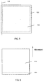
- FIG. 5 is a top plan view of one embodiment of the present invention wherein peripheral edges 102 of the first and second barrier sheets are sealed together around a permanent suppport 104 of the self-contained imaging assembly, and a perforation line 106 is provided for facilitating the peeling off of the barrier sheets.
- the peripheral edges of the barrier sheets, extending beyond the permanent support 104 of the self-contained assembly 104, may be sealed or bonded together using peelable adhesives. Alternatively, the edges of the films can be heat sealed together or they can be sealed by any other techniques.
- FIG. 6 is a top plan view of another embodiment of FIG. 3 according to the present invention in which a barrier sheet extending beyond the permanent support 112 of the imaging assembly, comprises with a trailing edge flap 114 for facilitating the peeling off of the barrier sheet from the permanent support 112.
- the bottom support of the imaging assembly may be a conventional.
- One common and conventional support for example, is polyethylene terephthalate (PET) containing an opacifying agent, paper or paper lined with film such as polyethylene, polypropylene, polyester, etc.
- PET polyethylene terephthalate
- Opaque films can be composites or admixtures of the polymer and the opacifying agent or pigment in a single layer.
- the opacifying agent can be provided in a separate layer underlying or overlying a polymer film such as PET.
- the opacifying agent employed in these materials is an inert, light-reflecting material which exhibits a white opaque background.
- opacifying agent Materials useful as the opacifying agent include inert, light-scattering white pigments such as titanium dioxide, magnesium carbonate or barium sulfate.
- the opacifying agent is titanium dioxide.
- the opaque support for example, may be a polyethylene terephthalate support containing 10% titanium dioxide which provides a bright white. Such a support is commercially available from DuPont Co. under the product designation MelinexTM.
- the second support comprises in order starting from the outside of the assembly: a backing layer, a tie (i.e., adhesive) layer, a paper layer, a tie layer, and a biaxially oriented microvoided polyolefin or resin coated pigmented polyolefin layer.
- a tie i.e., adhesive
- the face side of the opaque support which is the side closest to the imaging layer, has a light reflectance of greater than 90 percent, preferably greater than 95%.
- the second support is opaque, has a thickness of 12 to 250 microns and comprises in order starting from the outside surface of the assembly: a backing layer, a tie layer, a paper layer, a tie layer, and a biaxially oriented microvoided polyolefin or resin coated pigmented polyolefin layer.
- the face side of the opaque support preferably has a light reflectance of greater than 90 percent, preferably greater than 95%.
- the tint of the opaque may be modified to compensate for the yellowish color of the developer when employing phenolic resin which tends to have a yellowish color.
- the second support is transparent, it preferably has a light transmission which is the same as that described above for the first support, which light transmission is at least 80% at a wavelength of 500 nm.
- the same material may be used for both the top and bottom supports. Using the same material for both the top and bottom supports has the advantage of reducing curl of the self-contained assembly.
- barrier sheets in the preferred embodiment may optionally be sealed.
- the edges of the films can be heat sealed together or they can be sealed by any other techniques.
- the barrier sheets are sealed using a heat sealing method such as a heat knife. There may be a small gap between the sealed edges and the image area where a cut can be made to peel off the moisture barrier layer.
- One of more edges of the barrier sheets may also be optionally perforated, in the area between the sealed edges and the image, to make it easy for the users to remove the barrier sheet (which may be a single layer or a multilayer sheet).
- perforating sheets can be perforated "off-line” using, for example, a perforating wheel or die, spikes, or an electrostatic discharge. Machines for carrying out these operations are commercially available as for example from Rollem Corp (Hempstead, NY).
- a suitable peelable adhesive material for removably adhering the barrier sheets to the imaging assembly may be any adhesive which has a low cohesive strength, bonds well to paper or plastic.
- Preferred peelable adhesives are water-based polymer latexes or hot melt adhesives such as waxes or polymeric resins such as those taught by Doll et al, U.S. Pat. No. 5,039,652, Gozdecki at al., U. S. Pat. No. 5,639,529, and Washburn U. S. Pat. No. 5,756,175.
- Exemplary peelable adhesive that may be used is that used by Moore Business Forms, Inc. of Lake Forest, Ill., on its NOTE STIX.RTM business forms or sold under the trademark CLEANTACTM.
- An especially preferred class of adhesives may be chosen from blends of polyvinyl acetate and polyethylene emulsions. Such blends are formulated by varying the ratio of these two emulsions. Such adhesives are commercially available. The peel strength of these blends may be varied by varying the ratios of polyvinyl acetate to polyethylene.
- Suitable physical properties for such a peelable adhesive are: a viscosity of from 3500 to 4500 centipoise at 30 degrees centigrade; a specific gravity of 0.98 to 1.15 grams per cubic centimeter; an oven dry solids content of 43% to 57%; and a pH from 4.5 to 8.5.
- the adhesive is preferably applied at a rate of from 3.0 to 22.0 grams per square meter, and most preferably 3.0 to 12.0 grams per square meter, based on dry weight.
- the peelable adhesive provides a uniform non-fiber tearing clean release from paper or plastic.
- Preferred release levels may be in the range of from 100 to 500 grams per five centimeters of width, although somewhat higher and lower values are operational.
- the release test is conducted at 90-degree peel at 1500 centimeters per minute by delaminating the face material from the backing sheet.
- a peelable adhesive suitable for use in the present invention may generally be identified as one in which cohesive failure occurs as the face sheet is peeled from the imaging assembly. Cohesive failure is defined as that which occurs within the layer of adhesive. Adhesive failure is also acceptable. Adhesive failure is defined as failure at the interface between the adhesive and one of the surfaces it contacts.
- the adhesive may be applied over substantially the entire area of the barrier sheet during manufacture, may be confined to the peripheral edges only, or may be applied in any desired configuration which will ensure that the moisture barrier sheet and imaging assembly will not delaminate prematurely.
- the peelable adhesive may be applied in strips across the surfaces of the moisture barrier sheet and imaging assembly. Any feed holes and perforations may also be punched or cut at this time.
- One of more edges of the self-contained assembly may also be perforated, in the area between the sealed edges and the image, to make it easy for the customers to remove the moisture barrier sheet or, if there are two, barrier sheets.
- Adhesive materials useful for adhering the second support to the emulsion or imaging layer can be selected from the general class of "modified acrylics” that have good adhesion, which may be formulated with improved "tack” by addition of tackifying resins or other chemical additives.
- a useful adhesive must be designed for high initial adhesion and for adhesion to plastic substrates like polyester. It must have the ability to flow quickly for laminating to porous material (the imaging layer) and yet be inert with respect to the imaging layer.
- High strength adhesives useful in this invention are the film label stock adhesives of the 3M Company; including 3M's #300 and #310 adhesive formulas which exhibit "inertness" to the imaging layer.
- adhesives useful in this invention are aqueous-based adhesives such as AerosetTM 2177 or AerosetTMt 2550, 3240, and 3250 which are commercially available from Ashland Chemical Co., PD 0681, AP 6903, and W 3320 available from H. B. Fuller, or solvent-based pressure sensitive adhesives such as PS 508 sold by Ashland Chemical Co.
- the adhesives may be used separately or in combination.
- the adhesive is transparent or translucent and most preferably it is a transparent adhesive which remains transparent even after subjecting the assembly to actinic radiation and pressure necessary to image-wise expose and rupture the microcapsules.
- the amount of the adhesive will vary depending on the nature of the adhesive and the support.
- the adhesive is generally applied in an amount of 0.5 to 20 g/m 2 .
- a subbing layer for promoting adhesion between the transparent support and the imaging layer must have good compatibility with the imaging layer, must be transparent, must not effect the sensitometric response of the imaging layer, and must be chemically stable.
- Amorphous polyesters which may be applied as an aqueous dispersion, have been found to work well as the subbing layer material. Polymers with molecular weights of 5,000-15,000, with a low hydroxyl number and low acid number, can be employed, for example, the AQ polymers from Eastman Chemical Co. and, more particularly, AQ38 and AQ55.
- the subbing layer is coated onto the transparent support at a dried coating weight of from 0.1 to 5.0 g/m 2 , with a preferred dried coating weight of from 0.5 to 2.0 g/m 2 .
- the subbing layer also includes an ultraviolet (UV) ray absorber.
- UV ultraviolet
- Many types of UV absorbing materials have been described in the prior art, including U.S. Pat. Nos. 3,215,530, 3,707,375, 3,705,805, 3,352,681, 3,278,448, 3,253,921, 3,738,837, 4,045,229, 4,790,959, 4,853,471, 4,865,957, and 4,752,298, 5,977,219, 5,538,840 and United Kingdom Patent 1,338,265.
- Most preferred UV absorbers are polymeric UV absorbers prepared by the method described in U.S. Pat. Nos.
- Suitable photohardenable compositions, photoinitiators, chromogenic materials, carrier oils and encapsulation techniques for the layer of microcapsules are disclosed in U.S. Pat. No. 4,440,846; 4,772,541; and 5,230,982. Although the latter photohardenable compositions are non-silver systems, silver-based photohardenable microencapsulated system such as that described in U.S. Pat. Nos. 4,912,011 ; 5,091,280 and 5,118,590 and other patents assigned to Fuji Photo Film Co are also suitable for use in the present invention.
- a full color imaging system in which the microcapsules are sensitive to red, green, and blue light, respectively.
- the photohardenable composition in at least one and preferably all three sets of microcapsules may be sensitized by a cationic dye-borate anion complex, e.g., a cyanine dye/borate complex as described in U.S. Pat. No. 4,772,541.
- the microcapsules are sensitive (lambda max) at 450 nm, 540 nm, and 650 mn, respectively.
- Such a system is useful with visible light sources in direct transmission or reflection imaging.
- Such a material is useful in making contact prints or projected prints of color photographic slides. They are also useful in electronic imaging using lasers, light emitting diodes, liquid crystal displays or pencil light sources of appropriate wavelengths.
- cationic dye-borate anion complexes absorb at wavelengths greater than 400 nm, they are colored.
- the unreacted dye complex present in the microcapsules in the low density image areas can cause undesired coloration in the background area of the final picture, for example, the mixture of microcapsules tends to be green which may give the low density image areas a slight greenish tint.
- Approaches to reducing undesired coloration in the low density image area as well as the developed image include reducing the amount of photoinitiator used, adjusting the relative amounts of cyan, magenta and yellow microcapsules, or providing a compensating tint in the white opaque support.
- the photohardenable compositions used in the microcapsules may also contain a disulfide coinitiator.
- a disulfide coinitiator examples of useful disulfides are described in U.S. Pat. No. 5,230,982 .
- the amount of the photoinitiators used in the microcapsules can be reduced to levels such that the background coloration or residual stain is less than 0.3 and preferably less than 0.25 density units.
- the photohardenable compositions of the present invention can be encapsulated in various wall formers using conventional techniques, including coacervation, interfacial polymerization, polymerization of one or more monomers in an oil, as well as various melting, dispersing, and cooling methods.
- an encapsulation technique be used that provides high quality capsules which are responsive to changes in the internal phase viscosity in terms of their ability to rupture. Because the borate tends to be acid sensitive, encapsulation procedures conducted at higher pH (e.g., greater than 6) are preferred. Melamine-formaldehyde capsules are particularly useful.
- 4,962,010 discloses a conventional encapsulation useful in the present invention in which the microcapsules are formed in the presence of pectin and sulfonated polystyrene as system modifiers.
- a capsule size should be selected which minimizes light attenuation.
- the mean diameter of the capsules used in this invention typically ranges from approximately 1 to 25 microns. As a general rule, image resolution improves as the capsule size decreases.
- the capsules can range in size from one or more microns up to the point where they become visible to the human eye.
- the developer materials employed in carbonless paper technology are useful in the present invention.
- Illustrative examples are clay minerals such as acid clay, active clay, attapulgite, etc.; organic acids such as tannic acid, gallic acid, propyl gallate, etc.; acid polymers such as phenol-formaldehyde resins, phenol acetylene condensation resins, condensates between an organic carboxylic acid having at least one hydroxy group and formaldehyde, etc.; metal salts of aromatic carboxylic acids or derivatives thereof such as zinc salicylate, tin salicylate, zinc 2-hydroxy napththoate, zinc 3,5 di-tert butyl salicylate, zinc 3,5-di-(a-methylbenzyl)salicylate., oil soluble metals salts or phenol-formaldehyde novolak resins (e.g., see U.S.
- the particle size of the developer material can affect the quality of the image.
- the developer particles are selected to be in the range of 0.2 to 3 microns, preferably in the range of 0.5 to 1.5 microns.
- suitable binders selected from polyethylene oxide, polyvinyl alcohol, polyacrylamide, acrylic latices, neoprene emulsions, polystyrene emulsions, and nitrile emulsions, etc.
- a preferred developer material is one which provides good compatibility with the microcapsule slurry solution, for example Schenectady International resin HRJ-4250 solution.
- the self-contained imaging assembly used as photosensitive recording medium is not limited to the embodiments that have been described before, but different variations or modifications thereof are possible.
- the photocurable resin and the polymerization initiator instead of encapsulating the photocurable resin and the polymerization initiator inside the microcapsules of the self-contained imaging assembly, the photocurable resin and the polymerization initiator can also be included in the material constituting the microcapsules.
- the self-contained imaging assembly can contain photo-softening microcapsules, for example, microcapsules which have sufficient strength in the unexposed state, and which soften when exposed to light of a predetermined wavelength. In this case it is desirable to perform thermal-curing by heat-fixing.
- red, green and blue light it is not necessary to use red, green and blue light to capture the image in the imaging layer; depending on the characteristics of the photosensitive recording medium, light with various wavelengths can be selected.
- light emitting elements producing infrared light, red, and green, or light emitting elements producing far infrared light, near infrared light, and red can also be selected.
- Ultraviolet and far ultraviolet are also advantageous examples of valid color choices for light emitting elements.
- the number of colors of the light emitting elements is not limited to the three colors red, green, and blue; it is equally possible to use only one or two colors, or to select four colors, as in a typical color printer using yellow, magenta, cyan, and black, or even more colors.
- the choice of light emitting elements includes, but is not limited to LEDs, electroluminescent lamps (EL), light emitting plasma and laser devices, and other light emitting elements.
- the manufacture of an assembly according to the present invention can -, for example, be submanufactured by lamination of the transparent first support, including, for example, a polyester layer and a subbing/UV layer.
- an opaque support can be submanufactured by lamination of separate materials, for example a polyolefinic material and a paper layer. The materials may be formed into an opaque support with the addition of a backing/matt layer.
- An emulsion or image layer can then be applied to the clear support to form a first of two components of the assembly. This emulsion-containing component can then be combined with the assembled opaque support to form a final laminate which can be cut into individual imaging medium.
- the moisture barrier sheet/sheets can be added as the next step in the manufacturing process after the imaging layer and the supports have been put together.
- the imaging layer and supports are first equilibrated at a desired relative humidity before the barrier sheets are adherently and removably applied.
- the barrier sheets may then be cut and edge sealed and then packaged and bar coded.
- a subbing layer is provided between one of the supports and the imaging layer and an adhesive is provided between the other support and the imaging layer.
- the subbing layer will typically be located between the first support and the imaging layer.
- which support receives the subbing layer and which support receives the adhesive is a function of which support is coated with the wet imaging layer composition and which is assembled with the coated and dried imaging layer.
- the support which is coated with the imaging layer composition (which is typically the front support) will be provided with the subbing layer and the support which is assembled will receive the adhesive.
- the subbing layer is formed from a compound having chemical moieties such as hydroxy groups which will react with and bind to the microcapsules.
- the above-described imaging assembly is processed by exposing the front of the imaging assembly to light to form a latent image, developing the latent image by means of the color former coming out of the microcapsules when pressure is applied to the imaging assembly in a printer, discharging the imaging assembly from the printer and, following complete formation of an image, separating (ripping open) the first barrier sheet from the second barrier sheet and then removing the first and second barrier sheets from the imaging assembly.
- the imaging assembly of the present invention can be exposed in any suitable cameras or other exposure devices to provide an image.
- the imaging assembly of this invention is especially suitable for exposure using a liquid crystal array or light emitting diodes driven by a computer generated signal or a video signal for the reproduction of images from a video cassette recorder, a camcorder, or the like. It is possible to utilize, for example, with the current state of technology, a very economical compact printer, weighing under 500 g and having a size less than 100,000 mm 3 that prints directly from a digital camera utilizing a CompactFlashTM card interface and provides a resolution of 150 ppi or more with continuous tone and over 250 gradation levels.
- the print is "developed,” based on the "latent image” formed by the selectively photohardened microencapsulated color formers, by the application of pressure or by the application of both heat and pressure.
- the latent image is formed by a movement in the main scanning direction of an LED-type exposure head. Thereafter, an upper nip roller of a developing mechanism is moved from a separated position to a pressing position.
- the capsules that have not been photohardened are ruptured by pressure and a full color image is formed on the sheet, heat-fixing (which is optional to the present invention) is performed by a film heater, and the imaged assembly is discharged from the front of the housing for the device or printer.
- a typical pressure-type image-forming device typically comprises a printer housing with a lightproof cartridge for accommodating photosensitive imaging media (alternately referred to as recording media) mounted to the front of the printer housing so as to be easily detachable.
- a preheater is employed for preheating the photosensitive imaging medium.
- a typical exposure mechanism may include an exposure head for exposing while scanning in a direction perpendicular to the surface of the drawing and a developing mechanism for pressure development by means of a pair of an upper and a lower nip roller. The roller may be maintained under pressure by a spring.
- An optional fixing heater for heat-fixing the developed photosensitive imaging medium may be used.
- a discharge tray may be provided at the rear end of the printer housing.
- the pressure sensitive printer may be designed so that sheets are both fed and discharged at the front side of the printer housing.
- An image forming device for treatment of the imaging media can, for example, comprise exposure means for forming a latent image on the imaging medium upon exposure based on image information, developing means for developing the latent image by means of the coloring material coming out of the microcapsules when pressure is applied to the photosensitive imaging medium on which the latent image was formed by the exposure means, wherein the developing means comprise a pair of an upper and a lower nip roller facing each other and sandwiching the transport path of the photosensitive imaging medium, pressing means for pressing one nip roller against the other nip roller, roller switching means for alternately switching between a pressing position in which the one nip roller is brought into pressure contact with the other nip roller and a separated position in which the one nip roller is separated from the other nip roller, and a transport path for transporting the photosensitive imaging medium comprises a feed path for feeding the photosensitive imaging medium on the inlet side, a discharge path for discharging the recorded photosensitive imaging medium.
- the developing mechanism may comprise a pair of an upper and a lower nip roller, a rectangular frame fixed inside the printer housing for supporting the nip rollers, a pair of compression springs for pressing both ends of the roller axis of the upper nip roller toward the lower nip roller, and a roller switching mechanism for alternately switching between a pressing position in which the upper nip roller is brought into pressure contact with the lower nip roller and a separated position in which it is separated from the lower nip roller. If the pressing force of each of the springs is 150 kgf, the upper nip roller presses with a total force of 300 kgf on the lower nip roller. However, other means for applying pressure can be employed, for example, a pressure stylus.
- a control unit for the image-forming device may comprise a CPU, a ROM and a RAM, an I/O interface, and drive circuits, wherein a stepping motor for paper transport, a solenoid actuator for driving a switching plate, a film heater, a motor for roller switching, a stepping motor for driving the carriage, the exposure head, etc., are respectively connected to the drive circuits.
- a connector. and a control panel may also be connected to the control unit.
- image data (RGB image data) from an external host computer may be fed via a connector to the control unit.
- the ROM can store control programs for controlling all operations of the printer, a control program for calculating, from the input image data, the duration for which each LED of the exposure head is turned on and the timing thereof, a control program for controlling the transport of the self-contained imaging assembly by controlling the stepping motor for sheet transport synchronously with the exposure to green, red and blue light, a control program for controlling the scanning of the exposure head by controlling the stepping motor for driving the carriage synchronously with the exposure to green, red and blue light, etc.
- the different buffers and memory types necessary for running the control programs are in the RAM.
- the number of copies to be printed, the enlargement or reduction ratio of the image, the size of the image forming area of the imaging assembly, etc., input by an operator at the control panel, can be stored in the memory of the RAM. Exposure can take place upon calculation of the driving conditions for the stepping motor.
- the image data when image data of an image is sent to the control unit, the image data is divided into R image data, G image data, and B image data and stored in a buffer of the RAM.
- Each LED of an exposure heat can be electrically driven by a drive circuit via a cable.
- imaging medium sheets may be packaged as a stack of sheets which go into the printer.
- the individual sheets may be picked from the stack of sheets and transported into the "printing path" of the printer.
- the printer may become jammed, requiring disassembly by the user.
- the static in the sheets may be reduced or eliminated just prior to the final packaging; and a precision hinge on the printer film cassette or tray may be used.
- a method to further aid the feeding of sheets into the printer is to add a "back coat" to the imaging medium. This is preferably coated on the outer surface of the bottom or second support (which has the adhesive on the opposite side), typically the white support layer.
- This back coat material may be formulated to have some perceived aesthetic value (such as a writable or printable coating), but must have some difference relative to the adjacent next sheet surface which causes these surfaces not to adhere together.
- the preferred back coat material has a slight roughness to aid the "printer pickup roller” initiating the sheet movement into the printer, for example, a Sheffield Smoothness of 150-180 Sheffield units, such as a standard face matte coating on 3M label stock material.
- Other commercially available or known matte coatings can also be used.
- these coatings may include a binder and a grit or abrasive such as silica.
- the front side of the first support and the back side of the second support has a coefficient of friction of less than 0.4.
- Imaging media containing photohardenable microcapsules in an imaging layer commercially available from Cycolor, Inc, were obtained packaged in a plastic cartridge.
- the media in the cartridge were preconditioned at 80% relative humidity/70°F for 3 days. Prints were then made with some of these preconditioned media using a Vivtar VPP-150TM Photo Printer. These prints provided the sensitometric response for fresh media.
- the remaining preconditioned media were then removed from the cartridge and separated in a darkroom into two groups, Group I and Group II.
- the respective developed minimum color densities (Dmin) of prints from both groups were measured via a red filter, a green filter and a blue filter in order to obtain Dmin for the cyan dye, magenta dye, and yellow dye, respectively. The results thereof are shown in FIGS. 8 to 10.
- FIG. 8 shows the Dmin for the yellow dye for prints made from media from Group I and Group II (control) that were exposed to 40 % relative humidity for various times.
- Fig. 9 shows the Dmin for the magenta dye for prints made from media from Group I and Group II (control) that were exposed to 40 % relative humidity for various times.
- Fig. 10 shows the Dmin for the cyan dye for prints made from media from Group I and Group II (control) that were exposed to 40 % relative humidity for various times.
Landscapes
- Physics & Mathematics (AREA)
- General Physics & Mathematics (AREA)
- Engineering & Computer Science (AREA)
- Architecture (AREA)
- Structural Engineering (AREA)
- Photosensitive Polymer And Photoresist Processing (AREA)
- Materials For Photolithography (AREA)
Abstract
Description
- The present invention relates to an imaging assembly which comprises photohardenable microencapsulated coloring agents. Development is accomplished by the application of uniform pressure to the imaging assembly. Improved performance is obtained with respect to the imaging assembly's response to pressure by employing removable laminates as barrier sheets with respect to environmental humidity which laminates can be removed once the image is formed in the imaging assembly.
- The present invention relates to an imaging medium in the form of a self-contained imaging assembly and, more particularly, to an improved self-contained imaging assembly containing a photosensitive imaging layer or layers comprising photohardenable microcapsules encapsulating a coloring material and, outside the microcapsules, a developer material disposed between a first transparent support and a second support which may be opaque or transparent. The imaging medium or assembly can also be referred to as a recording medium, and the imaging layer can be referred to as a recording layer, since the assembly can serve both to capture an image (either the original image or an electronic copy), as does film, and also to display the image, as does a print. Consistent with this fact, the imaging assembly can form a positive image.
- The photosensitive imaging layer (including microcapsules) is colored by pressure development after exposure to radiation based on image information. The microcapsules, whose mechanical strength changes (increases) when exposed to light, are ruptured by means of pressure development, whereupon the coloring material and other substances encapsulated in the microcapsules flow out (to varying amounts based on the exposure) and development occurs. The coloring material, such as a substantially colorless color former, migrates to, and reacts with, the developer material and coloring occurs, whereupon a color image is developed.
- The "rupture" of the microcapsules is not an all-or-nothing event. Rather, the microcapsules exposed to light are differentially photocured to release varying amounts of color former in order to achieve tonal depth in the exposed area. The differential exposure to light proportionately increases the viscosity of the photocurable composition and thus immobilizes the color former proportionately to the desired tonal depth in the exposed area. The rupture of the microcapsules and the release of the color former is accomplished by the uniform application of pressure. Development of the photosensitive imaging layer can be accomplished, for example, by passing the imaging assembly between a pair of upper and lower nip rollers.
- Photohardenable imaging systems employing microencapsulated photosensitive compositions are the subject of various patents, including U.S. Pat. Nos. 4,399,209, 4,416,966, 4,440,846, 4,766,050, 5,783,353, and 5,916,727. Image forming devices (also referred to as printers) are disclosed, for example, in U.S. Pat. No. 4,740,809, wherein exposure occurs by guiding a light from a light source for a plurality of colors across a photosensitive recording medium. U.S. Pat. No. 4,992,822 discloses an image forming device, capable of producing a plurality of colors via a polygonal mirror, for repeatedly exposing the same pixels in a photosensitive recording medium. US Pat. No. 5,893,662 discloses a device for printing an image wherein the device can be incorporated into a computer bay. U.S. Pat. No. 4,648,699 describes a development technique which employs, instead of a pair of nip rollers, a point contact ball moving relative to the photosensitive recording medium.
- In the most typical embodiments, the photohardenable composition is a photopolymerizable composition including a polyethylenically unsaturated compound and a photoinitiator and is encapsulated together with a color former. Exposure to actinic radiation hardens the internal phase of the microcapsules. Then, as mentioned above, following exposure, the imaging media in the form of a sheet can be subjected to a uniform rupturing force by passing the sheet through the nip between a pair of pressure rollers.
- One of the problems in providing a self-contained imaging assembly that provides a high quality print is image stability or "keeping" which is affected by humidity sensitivity. It is known that print quality, and in particular sensitometric response to actinic radiation, can be significantly affected by sensitivity to humidity and the relative humidity of the environment. Even if the media is manufactured and packaged at a particular humidity, which is found optimum for print quality, variations after the media acclimates to a different later environment can adversely affect the sensitometric properties. This has been believed due to the materials employed in the imaging media, in particular the degree of hardening or curing of the internal phase of a microcapsule and the consequent change in the viscosity with the change in humidity. As a result thereof, photographic characteristics such as speed, maximum density and fogging density are changed from the original optimum. Furthermore, a full color imaging is adversely affected.
- In forming a full color image, color precursors which develop into yellow, magenta and cyan colors and photo-initiators corresponding to blue, green and red lights are encapsulated in an internal phase of the microcapsules, and the three sets of the microcapsules are mixed to prepare a full color imaging material containing a developer. The photographic characteristics of the respective microcapsules vary with the change in humidity to different degrees, which may result in muddy colors or incorrect or suboptimal colors. For example, when it is desired that a yellow color be developed, cyan and magenta capsules are cured by red and green lights, and only a yellow color former comes out of the ruptured capsules to react with a color-developer to form an image. However, if the cyan or magenta capsules insufficiently cure due to the change in humidity, the result may be a muddy color in which cyan or magenta is blended with yellow to some extent. Such muddy colors or other sensitometric phenomena due to the change in humidity has been a significant problem.
- One technique that has been used to address the humidity problem and to improve media stability resides is conditioning the layer containing the developer and microcapsules to a relative humidity (RH)of 10 to 40% and preferably 20%. For example, US Pat. Nos. 5,916,727 and 5,783,353 disclose conditioning the layer at 20% RH for 2 to 12 hours or more, at ambient temperatures, and subsequently sealing the assembly at this low RH level to assure that the layer is relatively moisture-free during the normal shelf-life of the assembly.
- US Patent No. 5,996,793 discloses storing the image-forming material together with a humidity-controlling material. Further, the patent discloses storing the image-forming material and the humidity-controlling material within a package made from a low-moisture permeable film. The low-moisture permeable film can be a plastic film on which is deposited a metal. Other low-moisture permeable films mentioned include fluorinated resins such as polytetrachloroethylene, polytrifluoroethylene, chlorinated rubber, polyvinylidene chloride, a copolymer of polyvinylidene chloride and acrylonitrile, polyethylene, polypropylene, polyesters, and films obtained by depositing a metal such as aluminum and a metal oxide such as silicon oxide.
- Unfortunately, when an open package of the imaging media is not used right away, especially if a plurality of media are stored for some time in a printing device prior to forming an image, the media may have an opportunity to adjust to ambient humidity and, especially in very dry or very humid climates, the RH of the media may decrease or increase substantially in a short time. Once the imaging media is removed from a package, it does not take very long for the environmental humidity to affect the media. Ambient humidity can soon penetrate the outside surface support on each side of the media causing a change in the moisture content within the media.
- After extensive investigations, applicants have found that humidity affects the mechanical properties of the imaging layers, as compared to the reaction properties of materials during photohardening of the imaging layer. The effect on mechanical properties causes undesirable variations in the degree of rupture of the microcapsules when the media is subjected to pressure during development. Although not wishing to be bound by theory, this may be due to the humidity changing the break strength of the capsules and/or it may be due to the change in the stiffness of the image layer which in turn alters the pressure applied to the microcapsules, more likely the latter.
- An object of the present invention is, therefore, to provide a self-contained photohardenable imaging assembly that is resistant to the effect of humidity and which will print consistently in response to a means for applying pressure to the assembly.
- It would be desirable to obtain an improved media that has no significant change in sensitometric properties with relative humidity, based on speed, Dmax, Dmin, tonal scale, and full color correctness.
- It would also be desirable to obtain an improved media that has improved Raw Stock Keeping (RSK), from manufacture to use.
- It would be particularly desirable if these objectives could be accomplished without requiring radical changes in conventional imaging chemistry, with respect to the microcapsules and the developer. It would be advantageous if these objectives could be attained in a product that was economical to manufacture and inexpensive for the customer to purchase.
- The prior art teaches that the transparent support through which the image is viewed can be formed from any transparent polymeric film, so long as a film is selected that provides good photographic quality when viewing the image and is preferably resistant to yellowing. The transparent support is typically a transparent polyethylene terephthalate (PET) support. Although the prior art use of polyethylene terephthalate (PET) provides a barrier to water vapor transmission to some extent and is transparent, it has now been found that a support or barrier that decreases the water vapor transmission to much lower levels while maintaining the desired thickness and high level of transparency provides unexpected improvement in the performance of the media with respect to pressure development.
- In the self-contained imaging assembly of the present invention, at least one imaging layer containing a developer and photohardenable microcapsules is placed between two support members to form an integral unit, wherein overlying at least one support is an adherently laminated removable sheet that provides a barrier to water vapor. A peelable adhesive may be included between the removable sheet and the support.
- In the imaging assembly of the invention, a first support is transparent and a second support may be transparent or opaque. In the latter case, an image is provided against a substantially white background as viewed through the transparent support and, in the former case, the image is viewed as a transparency preferably using an overhead or slide projector. Sometimes herein the first support may be referred to as the "front" support and the second support may be referred to as the "back" support.
- In a preferred embodiment of the invention, both supports of the imaging assembly are adherently laminated to removable sheets that provide a water-vapor barrier, wherein the transparent first support provides, only in combination with a transparent first barrier sheet, a water vapor transmission rate of less than 0.77 g/m2/day (0.05 g/100 in2/day), and wherein the second support (which may be opaque or transparent) provides, only in combination with a second barrier sheet, a water vapor transmission rate of less than 0.77 g/m2/day (0.05 g/100 in2/day). Suitably, each support is 10 to 250 micron thick. Preferably, the barrier sheet is 10 to 75 micron thick, more preferably 10 to 50 micron thick.
- Preferably, the two barrier sheets are temporarily sealed on the sides or edges to further prevent water vapor from permeating out of the imaging layer. This seal is maintained during printing of the image but may be removed in the final imaged product.
- In the event that the two barrier sheets are not sealed together, each barrier sheet may be removed merely by peeling away the barrier sheet after the image is formed. In a more preferred embodiment, however, the two barrier sheets are sealed at the edges. In this case, the imaging assembly according to the present invention may be processed by exposing the front of the imaging assembly to light to form a latent image, developing the latent image by the color former coming out of the microcapsules when pressure is applied to the imaging assembly in a printer, and after discharging the imaging assembly from the printer, separating (for example, ripping apart) the first barrier sheet from the second barrier sheet and removing them from the imaging assembly.
- A clear advantage of using the removable moisture barrier sheet/sheets is that it requires no fundamental changes in conventional imaging chemistry with respect to the imaging assembly, with respect to the microcapsules and the developer, and no fundamental changes in the manufacturing process. The moisture barrier sheet/sheets can be added as an additional step in the manufacturing process after the imaging layer and the supports have been put together and equilibrated at a desired relative humidity.
- FIG. 1 is a cross-sectional view of a prior-art imaging system.
- FIG. 2 is a cross-sectional view of the prior-art imaging system of FIG. 1 after exposure and microcapsule rupture.
- FIG. 3 is a cross-sectional view of an imaging system having a removable barrier sheet over the front support according to the present invention.
- FIG. 4 is a cross-sectional view of another embodiment of an imaging system having removable barrier sheet on both supports.
- FIG. 5 is a top plan view of one embodiment of the present invention wherein first and second barrier sheets are sealed together and a perforation line is provided for facilitating the peeling off of the barrier sheets.
- FIG. 6 is a top plan view of another embodiment of FIG. 3 according to the present invention with a trailing edge flap for facilitating the peeling off of the barrier layer.
- FIG. 7 shows, based on the results of Example 1 below, the Dmin change for a barrier treated media for use in the present invention, at 40% relative humidity and 70°F as a function of time, for a yellow dye.
- FIG. 8 shows, based on the results of Example 1 below, the Dmin change for a barrier treated media for use in the present invention, at 40% relative humidity at 70°F as a function of time, for a magenta dye.
- FIG. 9 shows, based on the results of Example 1, below the Dmin change for a barrier treated media for use in the present invention, at 40% relative humidity/70°F as a function of time, for a cyan dye.
-
- The present invention is directed to a self-contained imaging assembly for both developing and printing an image, which assembly provides improved image quality by reducing the variation in the sensitometric response of the media caused by changes in the relative humidity of the environment.
- By the term "raw stock keeping" (RSK) is meant the stability of the product from time of manufacture to time of use by the customer. Another metric of concern is "media shelf life" which is defined as the stability of the product from the time of opening a presealed package containing the media to the time of consumption (printing) of the media. Typically, a package may contain a plurality of media, for example 20 media.
- As mentioned above, the self-contained imaging assembly comprises an imaging layer or series of layers in which a color developing material (also referred to as a color developer) reacts with a dye precursor (also referred to as a color former) inside microcapsules. Typically, the microcapsules encapsulate photohardenable compositions comprising a photosensitive initiator and hardenable material that undergoes a change of mechanical strength when irradiated with light of a predetermined wavelength, wherein the plurality of microcapsules encapsulates at least one dye precursor for coloring when brought into contact with the color developing material.
- The plurality of microcapsules comprises three different types of microcapsules. The three types of microcapsules encapsulate the polymerization initiator, photocurable resin (each photocuring by irradiation with light of one of the three primary colors of light, respectively), and the colorless dye precursors for producing each of the colors of yellow, magenta and cyan. For example, when irradiating the self-contained imaging assembly with blue light (with a wavelength of 470 nm), the photocurable resin of the microcapsules containing only yellow dye precursors is photocured, and these microcapsules (yellow) differentially rupture (partially rupture or not rupture at all) during pressure development of the self-contained imaging assembly; however the microcapsules which were not photocured (magenta and cyan) rupture and the magenta and cyan dye precursors are forced out from the microcapsules and react with the color developing material, whereupon coloring occurs, and these colors mix to become a blue color, whereupon this blue color can be seen through the light-transmitting support.
- Further, when irradiating the self-contained imaging assembly with green light (with a wavelength of 525 nm), the photocurable resin of the microcapsules containing only magenta dye precursors is photocured, the yellow and cyan microcapsules are ruptured by pressure development, and as a result of the reaction of the color developing material with the yellow and cyan dye precursors the respective coloring occurs, whereupon these colors mix to become a green color. Moreover, when irradiating the self-contained imaging assembly with red light (with a wavelength of 650 nm), the photocurable resin of the microcapsules containing only cyan dye precursors is photocured, the yellow and magenta microcapsules are ruptured by pressure development, and as a result of the reaction of the color developing material with the yellow and magenta dye precursors the respective coloring occurs, whereupon these colors mix to become a red color.
- Furthermore, when all microcapsules are photocured to maximum hardness by exposure to light corresponding to the three types of microcapsules previously mentioned, they do not rupture even by pressure development. Therefore coloring does not occur, and the surface of the opaque support can be seen through the light-transmitting support, i.e. the surface color (white in the present embodiment) of the opaque support becomes the background color. In short, a color image is formed only in the areas where a coloring reaction occurred when the microcapsules ruptured. This coloring principal is sometimes called "self-coloring."
- A prior-art image assembly is illustrated in FIG. 1 which
imaging assembly 1 comprises in order: a firsttransparent support 2, asubbing layer 3, animaging layer 4 comprisingphotohardenable microcapsules 5 and adeveloper material 6, a layer ofadhesive 8, and asecond support 10 which may or may not contain anopacifying agent 12. By image-wise exposing this unit to actinic radiation, the microcapsules are differentially hardened in the exposed areas and the exposed unit can then be subjected to pressure to rupture the microcapsules. - FIG. 2 illustrates the prior-art imaging assembly of FIG. 1 after exposure and rupture of the
microcapsules 5. Rupturedmicrocapsules 16 release a color forming agent, whereupon thedeveloper material 6 reacts with the color forming agent to form animage 14. The image formed is viewed through thetransparent support 2 against thesupport 10 which can contain a white pigment. Typically, the microcapsules will consist of three sets of microcapsules sensitive respectively to red, green and blue light and containing cyan, magenta and yellow color formers, respectively, as described above and disclosed in U.S. Pat. No. 4,772,54 and U.S. Pat. No. 4,440,846. -
Imaging layer 4 typically contains 20 to 80% (dry weight) developer, 80 to 20% (dry weight) microcapsules and 0 to 20% of a binder. The layer is typically applied in a dry coat weight of 8 to 50 g/m2. An example of such a coating formulation is illustrated in Example 1 of US Patent No. 5,916,727. - The prior art teaches that in the self-contained photohardenable imaging assembly as shown in FIG. 1, the first
transparent support 2 through which the image is viewed can be formed from any transparent polymeric film, so long as a film is selected that provides good photographic quality when viewing the image and is preferably resistant to yellowing. Thefirst support 2 is typically a transparent polyethylene terephthalate (PET) or polyvinylchloride as the light-transmitting or transparent support. PET provides a barrier to water vapor transmission to some extent and is transparent. Of course, thicker coatings will provide a greater barrier to vapor transmission but, at some point, thicker layers begin to be disadvantaged by decreasing transparency, processibility, flexibility and the like. - The present invention is directed to a self-contained imaging system comprising at least one imaging layer containing a developer and photohardenable microcapsules, which imaging layer is placed between two support members to form an integral unit, wherein at least one support is adherently covered by a barrier sheet that is removable, such that the covered support provides, only in combination with the barrier sheet, a relatively low water vapor transmission rate.
- In one particularly preferred embodiment of the invention, both supports are adherently covered with a removable barrier sheet. To wit, the imaging system comprises a transparent first support which provides, in combination with a first barrier sheet, a water vapor transmission rate of less than 0.77 g/m2/day (0.05 g/100 in2/day). The first support in combination with the first barrier sheet has a light transmission of at least 80% at a wavelength at 550 nm. The second support which may be opaque or transparent also provides, in combination with a second barrier sheet, a water vapor transmission rate of less than 0.77 g/m2/day (0.05 g/100 in2/day). Preferably, in one embodiment of the invention, the front side of the first support and the back side of the second support has a coefficient of friction of less than 0.4. The supports suitably are 10 to 250 micron thick. Preferably, the barrier sheets are 10 to 75 micron thick, more preferably 10 to 50 micron thick.
- The barrier sheets may be adherently applied or laminated to a support, for example, by heat, pressure or by electostat means. In one embodiment, the removable parent barrier sheet is capable of being peeled off by hand. In the case where there are two barrier sheets, side edges (extending between the supports) may have holes, for example perfortated holes or sprocket holes, for assisting in transportation of the imaging assembly through the printer.
- By the term "support" is meant the permanent material extending from the outside of the assembly to the imaging layer, whether from the bottom or from the top, except not including any adhesive layer for promoting adhesion to the imaging layer. Thus, the removable (non-permanent) barrier sheet is not considered part of the permanent support.
- The removable barrier sheet may be a laminate comprising one or more barrier layers or the barrier sheet may consist entirely of a barrier layer. By the term "barrier layer" or "barrier material" is meant a material that preferably has a water vapor transmission rate of less than 0.77 g/m2/day (0.05 g/100 in2/day) by the ASTM F-1249 test. For purposes of defining the invention, the removable barrier sheet comprising the barrier layer is not considered part of the support. The support or barrier sheet may comprise layers that provide a higher water vapor transmission than the barrier layer material, so long as the water vapor transmission rate of the support and the barrier sheet together is less than 0.77 g/m2/day (0.05 g/100 in2/day). This barrier material must have a preselected combination of properties, including thickness (if too thick, too hazy, if too thin not sufficient support) and optical properties. In the case of barrier material for overlying the transparent first support, the barrier material must be highly transparent, colorless, practical and cost effective, and manufacturable or commercially available. This combination of properties is difficult to find in a single material. Many materials previously used in forming barriers in packaging do not meet all the necessary criteria alone or at all, for example, nylon, PC, PET, polyolefins, and saran polymers. The latter materials do not provide sufficient barrier properties unless resulting in thick layers that are impractical in the present invention. Some materials, while having good moisture barrier properties, have an unacceptable tint, for example silicon oxide coated polyester films. Some materials with exceptional moisture barrier properties are not transparent, for example, aluminum metallized film or paper.
- Thus, one embodiment of the present invention is directed to a self-contained photohardenable imaging assembly packaged for commercial sale wherein the assembly comprises, in order, a transparent first removable barrier sheet, a first transparent support that is 5 to 250 microns in thickness and has a light transmission in combination with the first barrier sheet of at least 80% at a wavelength of 550 nm, which provides, in combination with the removable first barrier sheet, a water vapor transmission rate of less than 0.77 g/m2/day (0.05 g/100 in2/day); one or more imaging layers comprising a plurality of microcapsules encapsulating a photohardenable composition and a color precursor which can react with a developing material in the same or an adjacent imaging layer; a second removable barrier sheet, and a second support which may be opaque or transparent that is 5 to 250 microns thick and which also provides, in combination with the removable second barrier sheet, a water vapor transmission rate of less than 0.77 g/m2/day (0.05 g/100 in2/day).
- In a preferred embodiment of the invention, the barrier sheets are sealed after the assembled imaging is preconditioned to a relative humidity within the range of 45 to 90%. The barrier sheets may be sealed by means of heat or other means.
- In yet another embodiment of the present invention, a self-contained photohardenable imaging assembly further comprises an intermediate layer comprising a relatively resilient material (compared to first transparent support), wherein the Young's modulus of the resilient material is 0.02 to 10 ksi. This has been found beneficial for reducing the change of pressure on microcapsules due to humidity variation.
- In one embodiment of the invention, the inner surface of each barrier sheet includes a peelable adhesive which secures the barrier sheet to the underlying support of the imaging assembly before and during printing. The peelable adhesive is removable from the surface of the imaging assembly.
- In yet another embodiment of the invention comprising at least one barrier sheet, wherein the barrier sheets are not sealed at the edges, the barrier sheet has substantially the same shape and area as the underlying support, except that the barrier sheet comprises a trailing edge larger than the underlying support of the imaging assembly so that the barrier sheet can be removed easily by grasping the trailing edge and peeling the barrier sheet from the underlying support.
- Alternatively, the removable barrier sheet may be on both back and front surfaces of the imaging assembly, in which case the removable layers may be edge sealed either by heat or by peelable adhesive. In one embodiment, the sealed barrier sheets may have a perforated line to facilitate removal of the barrier sheets.
- Materials which can be used as a barrier material for the barrier sheet, particularly in combination with a transparent support include, but are not limited to, fluorinated polymers, ceramic coated polymers, for example aluminum oxide, indium tin oxide, or silicon nitride coated on polyester or other transparent polymeric substrates, and other sheet materials meeting the above limitations. Especially preferred are Al2O3 vacuum deposited coatings on a polyester film (for example, Toppan™ GL-AE, available from Toppan Printing Co.) and chlorotrifluoroethylene homopolymer and copolymer films (for example, ACLAR™ films available from Honeywell Corp.). Aluminum oxide is an electrical insulator and is transparent to visible light. It is strong, hard material and resists attack by most chemicals. An aluminum oxide barrier coating can be deposited on a polymeric film substrate by vacuum deposition including chemical vapor deposition, electron beam evaporation, plasma-type sputtering process, ion assisted process such as ion plating, as well as others well known to those skilled in the art of vacuum coating or deposition.
- For example, a barrier material may be laminated to a polyester layer or other material having a lower water transmission rate, for example, a barrier sheet may comprise a polyester layer covered with a ceramic barrier layer or a halogenated polymeric barrier layer. The polyester layer may be on the outside or inside, or both the inside and the outside, of the barrier layer. Preferred polyester films include, but are not limited to, poly(ethylene terephthalate), poly(1,4-cyclohexanedimethylene terephthalate), poly(
ethylene 1,2-diphenoxyethane-4,4'-dicarboxylate), poly(butylene terephthalate), poly(ethylene naphthalate) and the like; and blends or laminates thereof with other polymers. Particularly preferred embodiments are poly(ethylene terephthalate) and poly(ethylene naphthalate). - FIG. 3 shows a first embodiment of a laminate structure for an imaging assembly according to the present invention. A
removable barrier sheet 82 is removably adhered by peelableadhesive layer 84 to a transparentpolyester supporting layer 86. The barrier sheet may consist, for example, of a thin polyester substrate coated by a ceramic barrier material consisting of Toppan GL-AE or Toppan GL-AL, mentioned above. Such materials contain an aluminum oxide ceramic material. A polyesterclear layer 86 may be further laminated with aprimer layer 88, and a UV absorbingsubbing layer 90. This clear permanent laminate 81 (includinglayers 86 through 90) forms the transparent support of theimaging layer 30. On the opaque side is anopaque support 98 comprising analuminum barrier layer 96 laminated between polymer layers, which opaque support is attached to theimaging layer 92 by anadhesive layer 94. - FIG. 4 shows a second embodiment of a laminate structure for an imaging assembly according to the present invention in which there are two removable barrier sheets. Removably adhered to the
transparent support 81 is a peelableadhesive layer 84 which in turn is adhered to a firstremovable barrier sheet 82. Apolyester supporting layer 86 may be laminated with aprimer layer 88 and a UV absorbingsubbing layer 90. Thelayers 86 through 90) forms the transparent opaque side to theimaging layer 92. On the opaque side is anadhesive layer 94 for attaching theopaque support 98 comprising awhitish material 99, for example a pigmented polyolefin, polyester, or cellulosic paper, laminated combinations thereof, and the like. A peelableadhesive layer 100 is provided for removably adhering asecond barrier sheet 101, which may be a metallic barrier sheet or, like the first barrier sheet, a transparent barrier sheet, comprising a ceramic material coated on a polyester substrate. Other barrier materials or layers meeting the requirements of the invention may be used. For example, optionally the barrier sheet may further comprise a pressure adhesive (permanent adhesive or subbing) adjacent the removable adhesive. - FIG. 5 is a top plan view of one embodiment of the present invention wherein
peripheral edges 102 of the first and second barrier sheets are sealed together around apermanent suppport 104 of the self-contained imaging assembly, and aperforation line 106 is provided for facilitating the peeling off of the barrier sheets. The peripheral edges of the barrier sheets, extending beyond thepermanent support 104 of the self-containedassembly 104, may be sealed or bonded together using peelable adhesives. Alternatively, the edges of the films can be heat sealed together or they can be sealed by any other techniques. - FIG. 6 is a top plan view of another embodiment of FIG. 3 according to the present invention in which a barrier sheet extending beyond the
permanent support 112 of the imaging assembly, comprises with a trailingedge flap 114 for facilitating the peeling off of the barrier sheet from thepermanent support 112. - The bottom support of the imaging assembly may be a conventional. One common and conventional support, for example, is polyethylene terephthalate (PET) containing an opacifying agent, paper or paper lined with film such as polyethylene, polypropylene, polyester, etc. Opaque films can be composites or admixtures of the polymer and the opacifying agent or pigment in a single layer. Alternatively, the opacifying agent can be provided in a separate layer underlying or overlying a polymer film such as PET. The opacifying agent employed in these materials is an inert, light-reflecting material which exhibits a white opaque background. Materials useful as the opacifying agent include inert, light-scattering white pigments such as titanium dioxide, magnesium carbonate or barium sulfate. In a preferred embodiment the opacifying agent is titanium dioxide. The opaque support, for example, may be a polyethylene terephthalate support containing 10% titanium dioxide which provides a bright white. Such a support is commercially available from DuPont Co. under the product designation Melinex™.
- In one embodiment of the invention, the second support comprises in order starting from the outside of the assembly: a backing layer, a tie (i.e., adhesive) layer, a paper layer, a tie layer, and a biaxially oriented microvoided polyolefin or resin coated pigmented polyolefin layer. Suitably, the face side of the opaque support, which is the side closest to the imaging layer, has a light reflectance of greater than 90 percent, preferably greater than 95%.
- In still another embodiment of the invention, the second support is opaque, has a thickness of 12 to 250 microns and comprises in order starting from the outside surface of the assembly: a backing layer, a tie layer, a paper layer, a tie layer, and a biaxially oriented microvoided polyolefin or resin coated pigmented polyolefin layer. Again, the face side of the opaque support preferably has a light reflectance of greater than 90 percent, preferably greater than 95%.
- The tint of the opaque may be modified to compensate for the yellowish color of the developer when employing phenolic resin which tends to have a yellowish color.
- In the event that the second support is transparent, it preferably has a light transmission which is the same as that described above for the first support, which light transmission is at least 80% at a wavelength of 500 nm. In this case, the same material may be used for both the top and bottom supports. Using the same material for both the top and bottom supports has the advantage of reducing curl of the self-contained assembly.
- The peripheral edges of barrier sheets in the preferred embodiment, extending around the self-contained assembly, may optionally be sealed. For example, the edges of the films can be heat sealed together or they can be sealed by any other techniques. In one embodiment, the barrier sheets are sealed using a heat sealing method such as a heat knife. There may be a small gap between the sealed edges and the image area where a cut can be made to peel off the moisture barrier layer.
- One of more edges of the barrier sheets may also be optionally perforated, in the area between the sealed edges and the image, to make it easy for the users to remove the barrier sheet (which may be a single layer or a multilayer sheet). There are several methods of perforating sheets. Sheets can be perforated "off-line" using, for example, a perforating wheel or die, spikes, or an electrostatic discharge. Machines for carrying out these operations are commercially available as for example from Rollem Corp (Hempstead, NY).
- An article entitled "Laser in the Paper Mill: Cutting, Perforating, or Scoring," (See P. Ratoff; J. E. Dennis; "Chem 26" 1973, 9, 50) describes the use of CO2 lasers to convert sheet materials. Ratoff also points out some advantages in the use of lasers to cut and perforate sheet materials (see P. Ratoff Pulp & Paper 1973, 47, 128). Uniformity, consistency of hole sizes, and no need for removal of residual paper waste are some of the advantages mentioned. Other articles describing the use of lasers to convert sheet materials include an article entitled "Laser Technology: Applications for Nonwovens and Composites" (W. E. Lawson;
Nonwovens World 1986, 1, 88) an article entitled "Cutting paper with electronic and laser beams," (H. Honicke; J. Albrecht The Paper Maker 1969, 46, 48). The use of lasers to perforate sheet materials is disclosed by Perrington et al. In U. S. Pat. No. 5,557,311 (1993). An apparatus for perforating sheet material using a laser is disclosed by W. H. Harding in U.S. Pat. No. 3,226,527 (1965). The use of laser energy to score, form a line of weakness, or perforate multilayer laminates containing thermoplastics, thermosets, paper, or foil is taught by Bowen in U.S. Pat. No. 3,909,582 and U.S. Pat. No. 3,790,744. An apparatus for perforating sheet material using a laser is disclosed by Harding in U.S. Pat. No. 3,226,527 (1965). - A suitable peelable adhesive material for removably adhering the barrier sheets to the imaging assembly may be any adhesive which has a low cohesive strength, bonds well to paper or plastic. Preferred peelable adhesives are water-based polymer latexes or hot melt adhesives such as waxes or polymeric resins such as those taught by Doll et al, U.S. Pat. No. 5,039,652, Gozdecki at al., U. S. Pat. No. 5,639,529, and Washburn U. S. Pat. No. 5,756,175. Exemplary peelable adhesive that may be used is that used by Moore Business Forms, Inc. of Lake Forest, Ill., on its NOTE STIX.R™ business forms or sold under the trademark CLEANTAC™.
- An especially preferred class of adhesives may be chosen from blends of polyvinyl acetate and polyethylene emulsions. Such blends are formulated by varying the ratio of these two emulsions. Such adhesives are commercially available. The peel strength of these blends may be varied by varying the ratios of polyvinyl acetate to polyethylene.
- Suitable physical properties for such a peelable adhesive are: a viscosity of from 3500 to 4500 centipoise at 30 degrees centigrade; a specific gravity of 0.98 to 1.15 grams per cubic centimeter; an oven dry solids content of 43% to 57%; and a pH from 4.5 to 8.5. The adhesive is preferably applied at a rate of from 3.0 to 22.0 grams per square meter, and most preferably 3.0 to 12.0 grams per square meter, based on dry weight.
- The peelable adhesive provides a uniform non-fiber tearing clean release from paper or plastic. Preferred release levels may be in the range of from 100 to 500 grams per five centimeters of width, although somewhat higher and lower values are operational. The release test is conducted at 90-degree peel at 1500 centimeters per minute by delaminating the face material from the backing sheet. A peelable adhesive suitable for use in the present invention may generally be identified as one in which cohesive failure occurs as the face sheet is peeled from the imaging assembly. Cohesive failure is defined as that which occurs within the layer of adhesive. Adhesive failure is also acceptable. Adhesive failure is defined as failure at the interface between the adhesive and one of the surfaces it contacts.
- The adhesive may be applied over substantially the entire area of the barrier sheet during manufacture, may be confined to the peripheral edges only, or may be applied in any desired configuration which will ensure that the moisture barrier sheet and imaging assembly will not delaminate prematurely. For example, the peelable adhesive may be applied in strips across the surfaces of the moisture barrier sheet and imaging assembly. Any feed holes and perforations may also be punched or cut at this time. Additionally, for ease of removal of the moisture barrier layer by the customer, there may be a small, adhesive-free gap area between the sealed/bonded edges and the image area where a cut can be made to provide a clean lifting edge for delamination by the recipient to peel off the moisture barrier layer. One of more edges of the self-contained assembly may also be perforated, in the area between the sealed edges and the image, to make it easy for the customers to remove the moisture barrier sheet or, if there are two, barrier sheets.
- Adhesive materials useful for adhering the second support to the emulsion or imaging layer can be selected from the general class of "modified acrylics" that have good adhesion, which may be formulated with improved "tack" by addition of tackifying resins or other chemical additives. A useful adhesive must be designed for high initial adhesion and for adhesion to plastic substrates like polyester. It must have the ability to flow quickly for laminating to porous material (the imaging layer) and yet be inert with respect to the imaging layer. High strength adhesives useful in this invention, for example, are the film label stock adhesives of the 3M Company; including 3M's #300 and #310 adhesive formulas which exhibit "inertness" to the imaging layer. Other examples of adhesives useful in this invention are aqueous-based adhesives such as Aeroset™ 2177 or Aeroset™t 2550, 3240, and 3250 which are commercially available from Ashland Chemical Co., PD 0681, AP 6903, and W 3320 available from H. B. Fuller, or solvent-based pressure sensitive adhesives such as PS 508 sold by Ashland Chemical Co. The adhesives may be used separately or in combination. Preferably, the adhesive is transparent or translucent and most preferably it is a transparent adhesive which remains transparent even after subjecting the assembly to actinic radiation and pressure necessary to image-wise expose and rupture the microcapsules. The amount of the adhesive will vary depending on the nature of the adhesive and the support. The adhesive is generally applied in an amount of 0.5 to 20 g/m2.
- A subbing layer for promoting adhesion between the transparent support and the imaging layer must have good compatibility with the imaging layer, must be transparent, must not effect the sensitometric response of the imaging layer, and must be chemically stable. Amorphous polyesters, which may be applied as an aqueous dispersion, have been found to work well as the subbing layer material. Polymers with molecular weights of 5,000-15,000, with a low hydroxyl number and low acid number, can be employed, for example, the AQ polymers from Eastman Chemical Co. and, more particularly, AQ38 and AQ55. The subbing layer is coated onto the transparent support at a dried coating weight of from 0.1 to 5.0 g/m2, with a preferred dried coating weight of from 0.5 to 2.0 g/m2.
- Preferably the subbing layer also includes an ultraviolet (UV) ray absorber. Many types of UV absorbing materials have been described in the prior art, including U.S. Pat. Nos. 3,215,530, 3,707,375, 3,705,805, 3,352,681, 3,278,448, 3,253,921, 3,738,837, 4,045,229, 4,790,959, 4,853,471, 4,865,957, and 4,752,298, 5,977,219, 5,538,840 and United Kingdom Patent 1,338,265. Most preferred UV absorbers are polymeric UV absorbers prepared by the method described in U.S. Pat. Nos. 4,496,650, 4,431,726, 4,464,462 and 4,645,735, 5,620,838,
EP 0 190 003, U.S. Pat. Nos. 3,761,272, 3,813,255, 4,431,726, 4,455,368, and 4,645,735. - Suitable photohardenable compositions, photoinitiators, chromogenic materials, carrier oils and encapsulation techniques for the layer of microcapsules are disclosed in U.S. Pat. No. 4,440,846; 4,772,541; and 5,230,982. Although the latter photohardenable compositions are non-silver systems, silver-based photohardenable microencapsulated system such as that described in U.S. Pat. Nos. 4,912,011; 5,091,280 and 5,118,590 and other patents assigned to Fuji Photo Film Co are also suitable for use in the present invention.
- In accordance with the preferred embodiments of the invention, a full color imaging system is provided in which the microcapsules are sensitive to red, green, and blue light, respectively. The photohardenable composition in at least one and preferably all three sets of microcapsules may be sensitized by a cationic dye-borate anion complex, e.g., a cyanine dye/borate complex as described in U.S. Pat. No. 4,772,541. For optimum color balance, the microcapsules are sensitive (lambda max) at 450 nm, 540 nm, and 650 mn, respectively. Such a system is useful with visible light sources in direct transmission or reflection imaging. Such a material is useful in making contact prints or projected prints of color photographic slides. They are also useful in electronic imaging using lasers, light emitting diodes, liquid crystal displays or pencil light sources of appropriate wavelengths.
- Because cationic dye-borate anion complexes absorb at wavelengths greater than 400 nm, they are colored. The unreacted dye complex present in the microcapsules in the low density image areas can cause undesired coloration in the background area of the final picture, for example, the mixture of microcapsules tends to be green which may give the low density image areas a slight greenish tint. Approaches to reducing undesired coloration in the low density image area as well as the developed image include reducing the amount of photoinitiator used, adjusting the relative amounts of cyan, magenta and yellow microcapsules, or providing a compensating tint in the white opaque support.
- The photohardenable compositions used in the microcapsules may also contain a disulfide coinitiator. Examples of useful disulfides are described in U.S. Pat. No. 5,230,982. By means of the optional use of such disulfides, the amount of the photoinitiators used in the microcapsules can be reduced to levels such that the background coloration or residual stain is less than 0.3 and preferably less than 0.25 density units.
- The photohardenable compositions of the present invention can be encapsulated in various wall formers using conventional techniques, including coacervation, interfacial polymerization, polymerization of one or more monomers in an oil, as well as various melting, dispersing, and cooling methods. To achieve maximum sensitivities, it is important that an encapsulation technique be used that provides high quality capsules which are responsive to changes in the internal phase viscosity in terms of their ability to rupture. Because the borate tends to be acid sensitive, encapsulation procedures conducted at higher pH (e.g., greater than 6) are preferred. Melamine-formaldehyde capsules are particularly useful. U.S. Pat. No. 4,962,010 discloses a conventional encapsulation useful in the present invention in which the microcapsules are formed in the presence of pectin and sulfonated polystyrene as system modifiers. A capsule size should be selected which minimizes light attenuation. The mean diameter of the capsules used in this invention typically ranges from approximately 1 to 25 microns. As a general rule, image resolution improves as the capsule size decreases. Technically, however, the capsules can range in size from one or more microns up to the point where they become visible to the human eye.
- The developer materials employed in carbonless paper technology are useful in the present invention. Illustrative examples are clay minerals such as acid clay, active clay, attapulgite, etc.; organic acids such as tannic acid, gallic acid, propyl gallate, etc.; acid polymers such as phenol-formaldehyde resins, phenol acetylene condensation resins, condensates between an organic carboxylic acid having at least one hydroxy group and formaldehyde, etc.; metal salts of aromatic carboxylic acids or derivatives thereof such as zinc salicylate, tin salicylate, zinc 2-hydroxy napththoate,
zinc zinc 3,5-di-(a-methylbenzyl)salicylate., oil soluble metals salts or phenol-formaldehyde novolak resins (e.g., see U.S. Pat. Nos. 3,672,935 and 3,732,120) such as zinc modified oil soluble phenol-formaldehyde resin as disclosed in U.S. Pat. No. 3,732,120, zinc carbonate etc. and mixtures thereof. The particle size of the developer material can affect the quality of the image. In one embodiment, the developer particles are selected to be in the range of 0.2 to 3 microns, preferably in the range of 0.5 to 1.5 microns. One or more suitable binders selected from polyethylene oxide, polyvinyl alcohol, polyacrylamide, acrylic latices, neoprene emulsions, polystyrene emulsions, and nitrile emulsions, etc. may be mixed with the developer and the microcapsules, typically in an amount of 1 to 8% by weight, to prepare a coating composition. A preferred developer material is one which provides good compatibility with the microcapsule slurry solution, for example Schenectady International resin HRJ-4250 solution. - The self-contained imaging assembly used as photosensitive recording medium is not limited to the embodiments that have been described before, but different variations or modifications thereof are possible. For example, instead of encapsulating the photocurable resin and the polymerization initiator inside the microcapsules of the self-contained imaging assembly, the photocurable resin and the polymerization initiator can also be included in the material constituting the microcapsules. Further, instead of photocurable microcapsules, the self-contained imaging assembly can contain photo-softening microcapsules, for example, microcapsules which have sufficient strength in the unexposed state, and which soften when exposed to light of a predetermined wavelength. In this case it is desirable to perform thermal-curing by heat-fixing.
- It is not necessary to use red, green and blue light to capture the image in the imaging layer; depending on the characteristics of the photosensitive recording medium, light with various wavelengths can be selected. For example, light emitting elements producing infrared light, red, and green, or light emitting elements producing far infrared light, near infrared light, and red can also be selected. Ultraviolet and far ultraviolet are also advantageous examples of valid color choices for light emitting elements. Moreover, the number of colors of the light emitting elements is not limited to the three colors red, green, and blue; it is equally possible to use only one or two colors, or to select four colors, as in a typical color printer using yellow, magenta, cyan, and black, or even more colors. Furthermore, the choice of light emitting elements includes, but is not limited to LEDs, electroluminescent lamps (EL), light emitting plasma and laser devices, and other light emitting elements.
- The manufacture of an assembly according to the present invention can -, for example, be submanufactured by lamination of the transparent first support, including, for example, a polyester layer and a subbing/UV layer. At the same time, an opaque support can be submanufactured by lamination of separate materials, for example a polyolefinic material and a paper layer. The materials may be formed into an opaque support with the addition of a backing/matt layer. An emulsion or image layer can then be applied to the clear support to form a first of two components of the assembly. This emulsion-containing component can then be combined with the assembled opaque support to form a final laminate which can be cut into individual imaging medium. The moisture barrier sheet/sheets can be added as the next step in the manufacturing process after the imaging layer and the supports have been put together. Preferably, the imaging layer and supports are first equilibrated at a desired relative humidity before the barrier sheets are adherently and removably applied. The barrier sheets may then be cut and edge sealed and then packaged and bar coded.
- In order to insure that the imaging system is effectively sealed between the supports, a subbing layer is provided between one of the supports and the imaging layer and an adhesive is provided between the other support and the imaging layer. For optical clarity, the subbing layer will typically be located between the first support and the imaging layer. However, which support receives the subbing layer and which support receives the adhesive is a function of which support is coated with the wet imaging layer composition and which is assembled with the coated and dried imaging layer. The support which is coated with the imaging layer composition (which is typically the front support) will be provided with the subbing layer and the support which is assembled will receive the adhesive. In accordance with the preferred embodiment of the invention, the subbing layer is formed from a compound having chemical moieties such as hydroxy groups which will react with and bind to the microcapsules.
- In a method of forming an image according to another aspect of the invention, the above-described imaging assembly is processed by exposing the front of the imaging assembly to light to form a latent image, developing the latent image by means of the color former coming out of the microcapsules when pressure is applied to the imaging assembly in a printer, discharging the imaging assembly from the printer and, following complete formation of an image, separating (ripping open) the first barrier sheet from the second barrier sheet and then removing the first and second barrier sheets from the imaging assembly.
- The imaging assembly of the present invention can be exposed in any suitable cameras or other exposure devices to provide an image. The imaging assembly of this invention is especially suitable for exposure using a liquid crystal array or light emitting diodes driven by a computer generated signal or a video signal for the reproduction of images from a video cassette recorder, a camcorder, or the like. It is possible to utilize, for example, with the current state of technology, a very economical compact printer, weighing under 500 g and having a size less than 100,000 mm3 that prints directly from a digital camera utilizing a CompactFlash™ card interface and provides a resolution of 150 ppi or more with continuous tone and over 250 gradation levels.
- The print is "developed," based on the "latent image" formed by the selectively photohardened microencapsulated color formers, by the application of pressure or by the application of both heat and pressure. See, for example, the image forming device described in US Patent No. 5,884,114 to Iwasaki, in which a photo and pressure sensitive printer provides the feeding and discharging of a photosensitive imaging medium at the front of the printer housing, which device can have the added advantage of being easily integrated into other equipment such as a personal computer. In this particular device, the latent image is formed by a movement in the main scanning direction of an LED-type exposure head. Thereafter, an upper nip roller of a developing mechanism is moved from a separated position to a pressing position. The capsules that have not been photohardened are ruptured by pressure and a full color image is formed on the sheet, heat-fixing (which is optional to the present invention) is performed by a film heater, and the imaged assembly is discharged from the front of the housing for the device or printer.
- A typical pressure-type image-forming device (which can be referred to as a printer) typically comprises a printer housing with a lightproof cartridge for accommodating photosensitive imaging media (alternately referred to as recording media) mounted to the front of the printer housing so as to be easily detachable. In some devices, a preheater is employed for preheating the photosensitive imaging medium. A typical exposure mechanism may include an exposure head for exposing while scanning in a direction perpendicular to the surface of the drawing and a developing mechanism for pressure development by means of a pair of an upper and a lower nip roller. The roller may be maintained under pressure by a spring. An optional fixing heater for heat-fixing the developed photosensitive imaging medium may be used. A discharge tray may be provided at the rear end of the printer housing. The pressure sensitive printer may be designed so that sheets are both fed and discharged at the front side of the printer housing.
- An image forming device for treatment of the imaging media can, for example, comprise exposure means for forming a latent image on the imaging medium upon exposure based on image information, developing means for developing the latent image by means of the coloring material coming out of the microcapsules when pressure is applied to the photosensitive imaging medium on which the latent image was formed by the exposure means, wherein the developing means comprise a pair of an upper and a lower nip roller facing each other and sandwiching the transport path of the photosensitive imaging medium, pressing means for pressing one nip roller against the other nip roller, roller switching means for alternately switching between a pressing position in which the one nip roller is brought into pressure contact with the other nip roller and a separated position in which the one nip roller is separated from the other nip roller, and a transport path for transporting the photosensitive imaging medium comprises a feed path for feeding the photosensitive imaging medium on the inlet side, a discharge path for discharging the recorded photosensitive imaging medium.
- In one embodiment, the developing mechanism may comprise a pair of an upper and a lower nip roller, a rectangular frame fixed inside the printer housing for supporting the nip rollers, a pair of compression springs for pressing both ends of the roller axis of the upper nip roller toward the lower nip roller, and a roller switching mechanism for alternately switching between a pressing position in which the upper nip roller is brought into pressure contact with the lower nip roller and a separated position in which it is separated from the lower nip roller. If the pressing force of each of the springs is 150 kgf, the upper nip roller presses with a total force of 300 kgf on the lower nip roller. However, other means for applying pressure can be employed, for example, a pressure stylus.
- A control unit for the image-forming device may comprise a CPU, a ROM and a RAM, an I/O interface, and drive circuits, wherein a stepping motor for paper transport, a solenoid actuator for driving a switching plate, a film heater, a motor for roller switching, a stepping motor for driving the carriage, the exposure head, etc., are respectively connected to the drive circuits. A connector. and a control panel may also be connected to the control unit. In one embodiment, image data (RGB image data) from an external host computer may be fed via a connector to the control unit.
- The ROM can store control programs for controlling all operations of the printer, a control program for calculating, from the input image data, the duration for which each LED of the exposure head is turned on and the timing thereof, a control program for controlling the transport of the self-contained imaging assembly by controlling the stepping motor for sheet transport synchronously with the exposure to green, red and blue light, a control program for controlling the scanning of the exposure head by controlling the stepping motor for driving the carriage synchronously with the exposure to green, red and blue light, etc. The different buffers and memory types necessary for running the control programs are in the RAM. The number of copies to be printed, the enlargement or reduction ratio of the image, the size of the image forming area of the imaging assembly, etc., input by an operator at the control panel, can be stored in the memory of the RAM. Exposure can take place upon calculation of the driving conditions for the stepping motor.
- In one type of image-forming device, when image data of an image is sent to the control unit, the image data is divided into R image data, G image data, and B image data and stored in a buffer of the RAM. Each LED of an exposure heat can be electrically driven by a drive circuit via a cable.
- In one embodiment of practicing the invention, imaging medium sheets may be packaged as a stack of sheets which go into the printer. The individual sheets may be picked from the stack of sheets and transported into the "printing path" of the printer. However, if two or more sheets at the same time are picked up and fed into the printing path the printer, the printer may become jammed, requiring disassembly by the user. To avoid this problem, the static in the sheets may be reduced or eliminated just prior to the final packaging; and a precision hinge on the printer film cassette or tray may be used. Also, a method to further aid the feeding of sheets into the printer is to add a "back coat" to the imaging medium. This is preferably coated on the outer surface of the bottom or second support (which has the adhesive on the opposite side), typically the white support layer. This back coat material may be formulated to have some perceived aesthetic value (such as a writable or printable coating), but must have some difference relative to the adjacent next sheet surface which causes these surfaces not to adhere together. The preferred back coat material has a slight roughness to aid the "printer pickup roller" initiating the sheet movement into the printer, for example, a Sheffield Smoothness of 150-180 Sheffield units, such as a standard face matte coating on 3M label stock material. Other commercially available or known matte coatings can also be used. In general, these coatings may include a binder and a grit or abrasive such as silica. Preferably, the front side of the first support and the back side of the second support has a coefficient of friction of less than 0.4.
- The present invention is illustrated in more detail by the following non-limiting example.
- This example illustrates the effect of a moisture barrier on the sensitometric response of an imaging assembly containing photohardenable microcapsules. Imaging media containing photohardenable microcapsules in an imaging layer, commercially available from Cycolor, Inc, were obtained packaged in a plastic cartridge. The media in the cartridge were preconditioned at 80% relative humidity/70°F for 3 days. Prints were then made with some of these preconditioned media using a Vivtar VPP-150™ Photo Printer. These prints provided the sensitometric response for fresh media. The remaining preconditioned media were then removed from the cartridge and separated in a darkroom into two groups, Group I and Group II. Individual samples of media in group I were packaged in separate bags made of a barrier material having a water vapor transmission rate of about 0.03 g/100in2/day in a darkroom at 80% relative humidity. The bag was made to essentially the same dimensions (length times width) as the media and was sealed on the edges by heat. The media in Group II were used as the control. Both groups of media were then kept in a darkroom at 40% relative humidity/ 70°F and prints were made with a Vivtar VPP-150™ Photo Printer at given time intervals, 0, 2, 4, 7, 14, 28, 35, 42 and 49 days, to determine the effect of the lower humidity on sensitometric response for the two groups of media. The Group I media were removed from the sealed bag just prior to printing. The respective developed minimum color densities (Dmin) of prints from both groups were measured via a red filter, a green filter and a blue filter in order to obtain Dmin for the cyan dye, magenta dye, and yellow dye, respectively. The results thereof are shown in FIGS. 8 to 10.
- FIG. 8 shows the Dmin for the yellow dye for prints made from media from Group I and Group II (control) that were exposed to 40 % relative humidity for various times.
- Fig. 9 shows the Dmin for the magenta dye for prints made from media from Group I and Group II (control) that were exposed to 40 % relative humidity for various times.
- Fig. 10 shows the Dmin for the cyan dye for prints made from media from Group I and Group II (control) that were exposed to 40 % relative humidity for various times.
- These experiments show that the Dmin for the control (Group II media) increased significantly after only 2 days. On the other hand, the Group I media that had a moisture barrier showed no change in Dmin after exposure to 40% relative humidity for as long as 35 days. The results of this study demonstrate that laminating the media with a barrier material according to the present invention would minimize variations in sensitometric response of the imaging assembly due to changes in humidity.
Claims (10)
- A self-contained imaging assembly comprising in order:a transparent first support 10 to 250 micron in thickness;at least one imaging layer comprising a plurality of photohardenable microcapsules encapsulating a color precursor which can react with a developer material in the same or an adjacent imaging layer;a second support which may be opaque or transparent;wherein a removable barrier sheet is adherently laminated to at least one support such that the support provides, only in combination with the barrier sheet, a vapor transmission rate of less than 0.77 g/m2/day (0.05 g/100 in2/day), and wherein, if the removable barrier sheet is adherently laminated to the first support, both the first support and the barrier layer together have a light transmission of at least 80% at a wavelength at 550 nm.
- The imaging assembly of claim 1 wherein the barrier sheet is 10 to 75 micron thick.
- The imaging assembly of claim 1 wherein a removable first barrier sheet and a removable second barrier sheet is adherently laminated, respectively, to the first support and second support such that the water vapor transmission rate, of each support and barrier sheet, is less than 0.77 g/m2/day (0.05 g/100 in2/day).
- The imaging assembly of claim 1 wherein said barrier sheet comprises a barrier layer selected from the group consisting of fluorinated polymers, inorganic oxides, and inorganic nitrides.
- The imaging assembly of claim 4 wherein said barrier layer is a fluorinated polymer derived primarily from trichlorofluoroethylene.
- The imaging assembly of claim 4 wherein said barrier layer is an inorganic oxide selected from aluminum oxide, indium tin oxide, and combinations thereof.
- The imaging assembly of claim 4 wherein said barrier layer comprises silicon nitride.
- A sealed self-contained photohardenable imaging assembly comprising in order:
a transparent removable barrier sheet adherently laminated to a transparent first support:a transparent first support 10 to 250 micron thick which provides, only in combination with the first barrier sheet, a water vapor transmission rate of less than 0.77 g/m2/day (0.05 g/100 in2/day) and wherein both the first support and the first removable barrier sheet together has a light transmission of at least 80% at a wavelength at 550 nm.at least one imaging layer comprising a plurality of photohardenable microcapsules encapsulating a color precursor which can react with a developer material in the same or an adjacent imaging layer;a second removable barrier sheet, which may be opaque or transparent, adherently laminated to a second support;a second support which may be opaque or transparent that is 10 to 250 micron in thickness, which provides, only in combination with the first barrier sheet, a water vapor transmission rate of less than 0.77 g/m2/day (0.05 g/100 in2/day). - The imaging assembly of claim 8 wherein said barrier sheet comprises a barrier layer selected from the group consisting of fluorinated polymers, inorganic oxides, and inorganic nitrides.
- A method of forming an image in a self-contained photohardenable imaging assembly, which imaging assembly comprises in order (a) a transparent removable barrier sheet adherently laminated to a transparent first support, (b) a transparent first support 10 to 250 micron thick which provides, only in combination with the first barrier sheet, a water vapor transmission rate of less than 0.77 g/m2/day (0.05 g/100 in2/day) and wherein both the first support and the first removable barrier sheet together has a light transmission of at least 80% at a wavelength at 550 nm, (c) at least one imaging layer comprising a plurality of photohardenable microcapsules encapsulating a color precursor which can react with a developer material in the same or an adjacent imaging layer, (d) a second removable barrier sheet, which may be opaque or transparent, adherently laminated to a second support; and (e) a second support which may be opaque or transparent that is 10 to 250 micron in thickness, which provides, only in combination with the first barrier sheet, a water vapor transmission rate of less than 0.77 g/m2/day (0.05 g/100 in2/day); which method comprises:(i) exposing the front of the imaging assembly to light to form a latent image;(ii) developing the latent image by the color former coming out of the microcapsules when pressure is applied in a printer to the imaging assembly;(iii) discharging the imaging assembly from the printer,(iv) separating the first barrier sheet from second barrier sheet and then removing the first and second barrier sheets from the imaging assembly.
Applications Claiming Priority (2)
| Application Number | Priority Date | Filing Date | Title |
|---|---|---|---|
| US553719 | 2000-04-20 | ||
| US09/553,719 US6537717B1 (en) | 2000-04-20 | 2000-04-20 | Self-contained imaging media comprising removable laminate |
Publications (1)
| Publication Number | Publication Date |
|---|---|
| EP1148382A1 true EP1148382A1 (en) | 2001-10-24 |
Family
ID=24210460
Family Applications (1)
| Application Number | Title | Priority Date | Filing Date |
|---|---|---|---|
| EP01201281A Withdrawn EP1148382A1 (en) | 2000-04-20 | 2001-04-09 | Self-contained imaging media comprising removable laminate |
Country Status (3)
| Country | Link |
|---|---|
| US (1) | US6537717B1 (en) |
| EP (1) | EP1148382A1 (en) |
| JP (1) | JP2001350256A (en) |
Cited By (1)
| Publication number | Priority date | Publication date | Assignee | Title |
|---|---|---|---|---|
| WO2003040825A1 (en) * | 2001-11-07 | 2003-05-15 | Hsbc Bank Usa | Method and apparatus for producing identification cards using photosensitive media employing microcapsules |
Families Citing this family (4)
| Publication number | Priority date | Publication date | Assignee | Title |
|---|---|---|---|---|
| US20050084790A1 (en) * | 2003-10-17 | 2005-04-21 | Eastman Kodak Company | Color developer composition and imaging element containing same |
| US6986979B2 (en) * | 2004-01-23 | 2006-01-17 | Eastman Kodak Company | Microcapsule composition |
| US20070116910A1 (en) * | 2005-11-23 | 2007-05-24 | Polykarpov Alexander Y | Multilayer laminated structures |
| US7971402B2 (en) * | 2008-02-22 | 2011-07-05 | Shawn Engberg | Ceiling structure for commercial kitchens |
Citations (5)
| Publication number | Priority date | Publication date | Assignee | Title |
|---|---|---|---|---|
| JPH04173389A (en) * | 1990-11-07 | 1992-06-22 | Fuji Photo Film Co Ltd | Photosensitive thermal recording material |
| WO1995034845A1 (en) * | 1994-06-10 | 1995-12-21 | Cycolor, Inc. | Self-contained imaging assembly and method for forming images therein |
| JPH10171123A (en) * | 1996-12-16 | 1998-06-26 | Brother Ind Ltd | Photosensitive pressure-sensitive recording medium |
| EP0872768A1 (en) * | 1997-04-15 | 1998-10-21 | Oriental Photo Industrial Co., Ltd. | Packing method and package for dry image-forming material |
| EP0980026A1 (en) * | 1998-03-02 | 2000-02-16 | Cycolor System Co., Ltd. | Dry image forming material and dry image forming method |
Family Cites Families (20)
| Publication number | Priority date | Publication date | Assignee | Title |
|---|---|---|---|---|
| US4138620A (en) * | 1978-03-24 | 1979-02-06 | Minnesota Mining And Manufacturing Company | Multi-panel electroluminescent light assembly |
| US4399209A (en) | 1981-11-12 | 1983-08-16 | The Mead Corporation | Transfer imaging system |
| US4440846A (en) | 1981-11-12 | 1984-04-03 | Mead Corporation | Photocopy sheet employing encapsulated radiation sensitive composition and imaging process |
| US4416966A (en) | 1982-08-25 | 1983-11-22 | The Mead Corporation | Capsular imaging system comprising decolorizing agent |
| US4648699A (en) | 1985-10-31 | 1987-03-10 | The Mead Corporation | Point contact development of imaging sheets employing photosensitive microcapsules |
| US4992822A (en) | 1986-04-01 | 1991-02-12 | Brother Kogyo Kabushiki Kaisha | Optical printing system |
| DE3710577A1 (en) | 1986-04-01 | 1987-10-08 | Brother Ind Ltd | OPTICAL PRINTING SYSTEM |
| US4766050A (en) | 1987-03-27 | 1988-08-23 | The Mead Corporation | Imaging system with integral cover sheet |
| GB2204142A (en) * | 1987-04-30 | 1988-11-02 | Brother Ind Ltd | Recording medium |
| US4977060A (en) * | 1989-12-07 | 1990-12-11 | The Mead Corporation | Method for producing microcapsules and photosensitive microcapsules produced thereby |
| US5112540A (en) * | 1989-12-14 | 1992-05-12 | The Mead Corporation | Method of making microcapsules having an improved pre-wall |
| JP2802696B2 (en) * | 1992-03-11 | 1998-09-24 | 富士写真フイルム株式会社 | Image receiving material and method of manufacturing the same |
| EP0593060B1 (en) * | 1992-10-15 | 1997-08-13 | Fuji Photo Film Co., Ltd. | Pressure-sensitive recording sheet |
| US5633113A (en) * | 1995-04-14 | 1997-05-27 | Polaroid Corporation | Mass transfer imaging media and methods of making and using the same |
| JPH10142702A (en) | 1996-11-05 | 1998-05-29 | Brother Ind Ltd | Image forming device |
| US6037094A (en) * | 1998-10-23 | 2000-03-14 | Cycolor, Inc. | Photosensitive material employing microcapsules and superabsorbent polymer |
| US6127084A (en) * | 1998-10-23 | 2000-10-03 | Cycolor, Inc. | Photosensitive material employing microcapsules containing a hygroscopic polymer in the internal phase |
| US6080520A (en) * | 1999-05-26 | 2000-06-27 | Cycolor, Inc. | Imaging system having opaque support |
| US6326120B1 (en) * | 2000-04-20 | 2001-12-04 | Eastman Kodak Company | Self-contained imaging media comprising microencapsulated color formers |
| US6365319B1 (en) * | 2000-04-20 | 2002-04-02 | Eastman Kodak Company | Self-contained imaging media comprising opaque laminated support |
-
2000
- 2000-04-20 US US09/553,719 patent/US6537717B1/en not_active Expired - Fee Related
-
2001
- 2001-04-09 EP EP01201281A patent/EP1148382A1/en not_active Withdrawn
- 2001-04-19 JP JP2001121096A patent/JP2001350256A/en active Pending
Patent Citations (5)
| Publication number | Priority date | Publication date | Assignee | Title |
|---|---|---|---|---|
| JPH04173389A (en) * | 1990-11-07 | 1992-06-22 | Fuji Photo Film Co Ltd | Photosensitive thermal recording material |
| WO1995034845A1 (en) * | 1994-06-10 | 1995-12-21 | Cycolor, Inc. | Self-contained imaging assembly and method for forming images therein |
| JPH10171123A (en) * | 1996-12-16 | 1998-06-26 | Brother Ind Ltd | Photosensitive pressure-sensitive recording medium |
| EP0872768A1 (en) * | 1997-04-15 | 1998-10-21 | Oriental Photo Industrial Co., Ltd. | Packing method and package for dry image-forming material |
| EP0980026A1 (en) * | 1998-03-02 | 2000-02-16 | Cycolor System Co., Ltd. | Dry image forming material and dry image forming method |
Non-Patent Citations (2)
| Title |
|---|
| DATABASE WPI Section Ch Week 199836, Derwent World Patents Index; Class G06, AN 1998-418106, XP002175017 * |
| PATENT ABSTRACTS OF JAPAN vol. 016, no. 477 (M - 1320) 5 October 1992 (1992-10-05) * |
Cited By (1)
| Publication number | Priority date | Publication date | Assignee | Title |
|---|---|---|---|---|
| WO2003040825A1 (en) * | 2001-11-07 | 2003-05-15 | Hsbc Bank Usa | Method and apparatus for producing identification cards using photosensitive media employing microcapsules |
Also Published As
| Publication number | Publication date |
|---|---|
| US6537717B1 (en) | 2003-03-25 |
| JP2001350256A (en) | 2001-12-21 |
Similar Documents
| Publication | Publication Date | Title |
|---|---|---|
| US6365319B1 (en) | Self-contained imaging media comprising opaque laminated support | |
| AU689336B2 (en) | Self-contained imaging assembly and method for forming images therein | |
| US4701397A (en) | Method for forming images on plain paper and an imaging sheet useful therein | |
| US6030740A (en) | Two-sided imaging material | |
| US4751165A (en) | Imaging sheet useful in forming images on plain paper comprising photosensitive microcapsules and developer-containing | |
| EP0165030B1 (en) | Pre-press proofing system incorporating antihalation layer | |
| US6326120B1 (en) | Self-contained imaging media comprising microencapsulated color formers | |
| US6468708B1 (en) | Self-contained humidity stabilized imaging media comprising microencapsulated color formers | |
| EP0755334B1 (en) | Slide blank | |
| US6544711B1 (en) | Self-contained imaging media comprising microencapsulated color formers and a ceramic barrier layer | |
| US6649318B1 (en) | Self-contained imaging media comprising microencapsulated color formers and a resilient layer | |
| US6537717B1 (en) | Self-contained imaging media comprising removable laminate | |
| US6383707B1 (en) | Self-contained imaging media comprising microencapsulated color formers and a halogenated polymeric support | |
| US5030538A (en) | Method for producing overhead transparencies having high color density images using a double sided image recording material | |
| US6387585B1 (en) | Self-contained imaging assembly having improved peel strength | |
| US20040224249A1 (en) | Self-contained imaging assembly with increased resistance to peeling |
Legal Events
| Date | Code | Title | Description |
|---|---|---|---|
| PUAI | Public reference made under article 153(3) epc to a published international application that has entered the european phase |
Free format text: ORIGINAL CODE: 0009012 |
|
| AK | Designated contracting states |
Kind code of ref document: A1 Designated state(s): AT BE CH CY DE DK ES FI FR GB GR IE IT LI LU MC NL PT SE TR Kind code of ref document: A1 Designated state(s): DE FR GB |
|
| AX | Request for extension of the european patent |
Free format text: AL;LT;LV;MK;RO;SI |
|
| 17P | Request for examination filed |
Effective date: 20020330 |
|
| AKX | Designation fees paid |
Free format text: DE FR GB |
|
| STAA | Information on the status of an ep patent application or granted ep patent |
Free format text: STATUS: THE APPLICATION HAS BEEN WITHDRAWN |
|
| 18W | Application withdrawn |
Effective date: 20051024 |