EP1148343A2 - Autocorrection of MR projection images for motion artifacts - Google Patents
Autocorrection of MR projection images for motion artifacts Download PDFInfo
- Publication number
- EP1148343A2 EP1148343A2 EP01106674A EP01106674A EP1148343A2 EP 1148343 A2 EP1148343 A2 EP 1148343A2 EP 01106674 A EP01106674 A EP 01106674A EP 01106674 A EP01106674 A EP 01106674A EP 1148343 A2 EP1148343 A2 EP 1148343A2
- Authority
- EP
- European Patent Office
- Prior art keywords
- image
- recited
- dimensional
- views
- cost function
- Prior art date
- Legal status (The legal status is an assumption and is not a legal conclusion. Google has not performed a legal analysis and makes no representation as to the accuracy of the status listed.)
- Granted
Links
Images


Classifications
-
- G—PHYSICS
- G01—MEASURING; TESTING
- G01R—MEASURING ELECTRIC VARIABLES; MEASURING MAGNETIC VARIABLES
- G01R33/00—Arrangements or instruments for measuring magnetic variables
- G01R33/20—Arrangements or instruments for measuring magnetic variables involving magnetic resonance
- G01R33/44—Arrangements or instruments for measuring magnetic variables involving magnetic resonance using nuclear magnetic resonance [NMR]
- G01R33/48—NMR imaging systems
- G01R33/54—Signal processing systems, e.g. using pulse sequences ; Generation or control of pulse sequences; Operator console
- G01R33/56—Image enhancement or correction, e.g. subtraction or averaging techniques, e.g. improvement of signal-to-noise ratio and resolution
- G01R33/565—Correction of image distortions, e.g. due to magnetic field inhomogeneities
- G01R33/56509—Correction of image distortions, e.g. due to magnetic field inhomogeneities due to motion, displacement or flow, e.g. gradient moment nulling
-
- G—PHYSICS
- G01—MEASURING; TESTING
- G01R—MEASURING ELECTRIC VARIABLES; MEASURING MAGNETIC VARIABLES
- G01R33/00—Arrangements or instruments for measuring magnetic variables
- G01R33/20—Arrangements or instruments for measuring magnetic variables involving magnetic resonance
- G01R33/44—Arrangements or instruments for measuring magnetic variables involving magnetic resonance using nuclear magnetic resonance [NMR]
- G01R33/48—NMR imaging systems
- G01R33/54—Signal processing systems, e.g. using pulse sequences ; Generation or control of pulse sequences; Operator console
- G01R33/56—Image enhancement or correction, e.g. subtraction or averaging techniques, e.g. improvement of signal-to-noise ratio and resolution
- G01R33/567—Image enhancement or correction, e.g. subtraction or averaging techniques, e.g. improvement of signal-to-noise ratio and resolution gated by physiological signals, i.e. synchronization of acquired MR data with periodical motion of an object of interest, e.g. monitoring or triggering system for cardiac or respiratory gating
- G01R33/5673—Gating or triggering based on a physiological signal other than an MR signal, e.g. ECG gating or motion monitoring using optical systems for monitoring the motion of a fiducial marker
-
- G—PHYSICS
- G06—COMPUTING OR CALCULATING; COUNTING
- G06T—IMAGE DATA PROCESSING OR GENERATION, IN GENERAL
- G06T1/00—General purpose image data processing
- G06T1/20—Processor architectures; Processor configuration, e.g. pipelining
-
- G—PHYSICS
- G06—COMPUTING OR CALCULATING; COUNTING
- G06T—IMAGE DATA PROCESSING OR GENERATION, IN GENERAL
- G06T12/00—Tomographic reconstruction from projections
- G06T12/20—Inverse problem, i.e. transformations from projection space into object space
-
- G—PHYSICS
- G06—COMPUTING OR CALCULATING; COUNTING
- G06T—IMAGE DATA PROCESSING OR GENERATION, IN GENERAL
- G06T5/00—Image enhancement or restoration
- G06T5/80—Geometric correction
-
- G—PHYSICS
- G01—MEASURING; TESTING
- G01R—MEASURING ELECTRIC VARIABLES; MEASURING MAGNETIC VARIABLES
- G01R33/00—Arrangements or instruments for measuring magnetic variables
- G01R33/20—Arrangements or instruments for measuring magnetic variables involving magnetic resonance
- G01R33/44—Arrangements or instruments for measuring magnetic variables involving magnetic resonance using nuclear magnetic resonance [NMR]
- G01R33/48—NMR imaging systems
- G01R33/4818—MR characterised by data acquisition along a specific k-space trajectory or by the temporal order of k-space coverage, e.g. centric or segmented coverage of k-space
- G01R33/482—MR characterised by data acquisition along a specific k-space trajectory or by the temporal order of k-space coverage, e.g. centric or segmented coverage of k-space using a Cartesian trajectory
- G01R33/4822—MR characterised by data acquisition along a specific k-space trajectory or by the temporal order of k-space coverage, e.g. centric or segmented coverage of k-space using a Cartesian trajectory in three dimensions
-
- G—PHYSICS
- G01—MEASURING; TESTING
- G01R—MEASURING ELECTRIC VARIABLES; MEASURING MAGNETIC VARIABLES
- G01R33/00—Arrangements or instruments for measuring magnetic variables
- G01R33/20—Arrangements or instruments for measuring magnetic variables involving magnetic resonance
- G01R33/44—Arrangements or instruments for measuring magnetic variables involving magnetic resonance using nuclear magnetic resonance [NMR]
- G01R33/48—NMR imaging systems
- G01R33/54—Signal processing systems, e.g. using pulse sequences ; Generation or control of pulse sequences; Operator console
- G01R33/56—Image enhancement or correction, e.g. subtraction or averaging techniques, e.g. improvement of signal-to-noise ratio and resolution
- G01R33/563—Image enhancement or correction, e.g. subtraction or averaging techniques, e.g. improvement of signal-to-noise ratio and resolution of moving material, e.g. flow contrast angiography
- G01R33/5635—Angiography, e.g. contrast-enhanced angiography [CE-MRA] or time-of-flight angiography [TOF-MRA]
-
- G—PHYSICS
- G01—MEASURING; TESTING
- G01R—MEASURING ELECTRIC VARIABLES; MEASURING MAGNETIC VARIABLES
- G01R33/00—Arrangements or instruments for measuring magnetic variables
- G01R33/20—Arrangements or instruments for measuring magnetic variables involving magnetic resonance
- G01R33/44—Arrangements or instruments for measuring magnetic variables involving magnetic resonance using nuclear magnetic resonance [NMR]
- G01R33/48—NMR imaging systems
- G01R33/54—Signal processing systems, e.g. using pulse sequences ; Generation or control of pulse sequences; Operator console
- G01R33/56—Image enhancement or correction, e.g. subtraction or averaging techniques, e.g. improvement of signal-to-noise ratio and resolution
- G01R33/565—Correction of image distortions, e.g. due to magnetic field inhomogeneities
- G01R33/56572—Correction of image distortions, e.g. due to magnetic field inhomogeneities caused by a distortion of a gradient magnetic field, e.g. non-linearity of a gradient magnetic field
-
- G—PHYSICS
- G06—COMPUTING OR CALCULATING; COUNTING
- G06T—IMAGE DATA PROCESSING OR GENERATION, IN GENERAL
- G06T2211/00—Image generation
- G06T2211/40—Computed tomography
- G06T2211/412—Dynamic
-
- G—PHYSICS
- G06—COMPUTING OR CALCULATING; COUNTING
- G06T—IMAGE DATA PROCESSING OR GENERATION, IN GENERAL
- G06T2211/00—Image generation
- G06T2211/40—Computed tomography
- G06T2211/424—Iterative
Definitions
- the field of the invention is nuclear magnetic resonance imaging methods and systems. More particularly, the invention relates to the correction of motion artifacts in MR images.
- polarizing field B 0 When a substance such as human tissue is subjected to a uniform magnetic field (polarizing field B 0 ), the individual magnetic moments of the spins in the tissue attempt to align with this polarizing field, but precess about it in random order at their characteristic Larmor frequency. If the substance, or tissue, is subjected to a magnetic field (excitation field B 1 ) which is in the x-y plane and which is near the Larmor frequency, the net aligned moment, M z , may be rotated, or "tipped", into the x-y plane to produce a net transverse magnetic moment M t . A signal is emitted by the excited spins after the excitation signal B 1 is terminated, this signal may be received and processed to form an image.
- excitation field B 1 which is in the x-y plane and which is near the Larmor frequency
- magnetic field gradients G x G y and G z
- the region to be imaged is scanned by a sequence of measurement cycles in which these gradients vary according to the particular localization method being used.
- the resulting set of received NMR signals are digitized and processed to reconstruct the image using one of many well known reconstruction techniques.
- Object motion during the acquisition of NMR image data produces both blurring and "ghosts" in the phase-encoded direction. ghosts are particularly apparent when the motion is periodic, or nearly so. For most physiological motion each view of the NMR signal is acquired in a period short enough that the object may be considered stationary during the acquisition window. In such case the blurring and ghosting is due to the inconsistent appearance of the object from view to view. Motion that changes the appearance between views such as that produced by a patient moving, by the respiration or the cardiac cycle, or by peristalsis, is referred to hereinafter as “view-to-view motion”. Motion may also change the amplitude and phase of the NMR signal as it evolves during the pulse sequence and such motion is referred to hereinafter as "in-view motion”.
- Both blurring and ghosting can be reduced if the data acquisition is synchronized with the functional cycle of the object to reduce view-to-view motion.
- This method is known as gated NMR scanning, and its objective is to acquire NMR data at the same point during successive functional cycles so that the object "looks" the same in each view.
- the drawback of gating is that NMR data may be acquired only during a small fraction of the object's functional cycle, and even when the shortest acceptable pulse sequence is employed, the gating technique can significantly lengthen the data acquisition.
- the view order is selected such that the variation period appears to be equal to the total NMR scan time (low frequency) so that the ghost artifacts are brought as close to the object being imaged as possible.
- the view order is chosen to make the variation period appear to be as short as possible so as to push the ghost artifacts as far from the object as possible.
- the most successful method for correcting MR images for motion artifacts employs navigator signals acquired during the scan. As described in U.S. Patent No. 4,937,526, such navigator signals are acquired periodically during the scan, and the information in these signals may be used to correct the image data for patient motion. Unfortunately, acquisition of the navigator signals increases the scan time.
- the present invention is a method for correcting images derived from image data acquired with an MRI system to form a k-space image data set; reconstructing an image from the k-space image data set; producing a derivative image by processing the reconstructed image; evaluating the quality of the derivative image by calculating a cost function based on the derivative image; and minimizing the cost function by making corrections to k-space views and repeating the steps.
- a general object of the invention is to extend the autocorrection process to correct images that are derived from acquired MRI data. Producing clinically useful images from a reconstructed MR image requires further processing that may result in a derivative image that is linearly or non-linearly related to the acquired MR image. It has been discovered that the autocorrection process can be extended to evaluate the final, derived image.
- a more specific object of the invention is to correct two dimensional projection images produced from acquired three-dimensional MR data.
- the projection process produces a two-dimensional image which is non-linearly related to the acquired MR data. Nevertheless, the autocorrection process according to the present invention converges to an image with substantially reduced motion artifacts.
- Fig. 1 there is shown the major components of a preferred MRI system which incorporates the present invention.
- the operation of the system is controlled from an operator console 100 which includes a keyboard and control panel 102 and a display 104.
- the console 100 communicates through a link 116 with a separate computer system 107 that enables an operator to control the production and display of images on the screen 104.
- the computer system 107 includes a number of modules which communicate with each other through a backplane. These include an image processor module 106, a CPU module 108 and a memory module 113, known in the art as a frame buffer for storing image data arrays.
- the computer system 107 is linked to a disk storage 111 and a tape drive 112 for storage of image data and programs, and it communicates with a separate system control 122 through a high speed serial link 115.
- the system control 122 includes a set of modules connected together by a backplane. These include a CPU module 119 and a pulse generator module 121 which connects to the operator console 100 through a serial link 125. It is through this link 125 that the system control 122 receives commands from the operator which indicate the scan sequence that is to be performed.
- the pulse generator module 121 operates the system components to carry out the desired scan sequence. It produces data which indicates the timing, strength and shape of the RF pulses which are to be produced, and the timing of and length of the data acquisition window.
- the pulse generator module 121 connects to a set of gradient amplifiers 127, to indicate the timing and shape of the gradient pulses to be produced during the scan.
- the pulse generator module 121 also receives patient data from a physiological acquisition controller 129 that receives signals from a number of different sensors connected to the patient, such as ECG signals from electrodes or respiratory signals from a bellows. And finally, the pulse generator module 121 connects to a scan room interface circuit 133 which receives signals from various sensors associated with the condition of the patient and the magnet system. It is also through the scan room interface circuit 133 that a patient positioning system 134 receives commands to move the patient to the desired position for the scan.
- the gradient waveforms produced by the pulse generator module 121 are applied to a gradient amplifier system 127 comprised of G x , G y and G z amplifiers.
- Each gradient amplifier excites a corresponding gradient coil in an assembly generally designated 139 to produce the magnetic field gradients used for position encoding acquired signals.
- the gradient coil assembly 139 forms part of a magnet assembly 141 which includes a polarizing magnet 140 and a whole-body RF coil 152.
- a transceiver module 150 in the system control 122 produces pulses which are amplified by an RF amplifier 151 and coupled to the RF coil 152 by a transmit/receive switch 154.
- the resulting signals radiated by the excited nuclei in the patient may be sensed by the same RF coil 152 and coupled through the transmit/receive switch 154 to a preamplifier 153.
- the amplified NMR signals are demodulated, filtered, and digitized in the receiver section of the transceiver 150.
- the transmit/receive switch 154 is controlled by a signal from the pulse generator module 121 to electrically connect the RF amplifier 151 to the coil 152 during the transmit mode and to connect the preamplifier 153 during the receive mode.
- the transmit/receive switch 154 also enables a separate RF coil (for example, a head coil or surface coil) to be used in either the transmit or receive mode.
- the NMR signals picked up by the RF coil 152 are digitized by the transceiver module 150 and transferred to a memory module 160 in the system control 122.
- an array processor 161 operates to Fourier transform the data into an array of image data.
- This image data is conveyed through the serial link 115 to the computer system 107 where it is stored in the disk memory 111.
- this image data may be archived on the tape drive 112, or it may be further processed by the image processor 106 and conveyed to the operator console 100 and presented on the display 104.
- transceiver 150 For a more detailed description of the transceiver 150, reference is made to U.S. patent Nos. 4,952,877 and 4,992,736 which are incorporated herein by reference.
- the preferred embodiment of the invention employs a 3D gradient recalled echo pulse sequence depicted in Fig. 3.
- an RF excitation pulse 220 having a flip angle of 60° is produced in the presence of a slab select gradient pulse 222 to produce transverse magnetization in the 3D volume of interest as taught in U.S. patent No. 4,431,968.
- a readout gradient pulse 228 directed along the x axis follows and a partial echo (60%) NMR signal 230 is acquired and digitized as described above.
- rewinder gradient pulses 232 and 234 rephase the magnetization before the pulse sequence is repeated as taught in U.S. patent No. 4,665,365.
- the pulse sequence is repeated and the phase encoding pulses 224 and 226 are stepped through a series of values to sample the 3D k-space.
- sixteen phase encodings are employed along the z axis and 128 phase encodings are employed along the y axis. For each particular y phase encoding, therefore, sixteen acquisitions with twelve different z phase encodings are performed to sample completely along the k z axis. This is repeated 128 times with 128 different y phase encodings to sample completely along the k y axis.
- Sampling along the k x axis is performed by sampling the echo signal 230 in the presence of the readout gradient pulse 228 during each pulse sequence. It will be understood by those skilled in the art that only a partial sampling along the k x axis is performed and the missing data is computed using a homodyne reconstruction or by zero filling. This enables the echo time (TE) of the pulse sequence to be shortened to less than 1.8 to 2.0 ms. and the pulse repetition rate (TR) to be shortened to less than 10.0 msecs.
- TE echo time
- TR pulse repetition rate
- the autocorrection method is employed to reduce image artifacts in k-space image data sets acquired with the MRI system of Fig. 1.
- a three-dimensional k-space image data set is acquired as indicated at process block 200
- an initial block of k-space views is selected for correction as indicated at process block 202.
- 64 views are selected in this initial block.
- the views in this block are then phase shifted as indicated at process block 204 based on an initial motion estimate.
- the altered three-dimensional k-space data set is then Fourier transformed as indicated at process block 206 to produce a three-dimensional image. While images may be produced simply by selecting a set of data points located in a cross section through one of the 3D data arrays 250-255, such images have limited diagnostic value. This is because blood vessels usually do not lie in a single plane and such cross sectional images show only short pieces or cross sections of many vessels that happen to pass through the selected plane. Such images are useful when a specific location in a specific vessel is to be examined, but they are less useful as a means for examining the health of the vascular system and identifying regions that may be diseased.
- Yet another technique used to produce projection images uses a 3D region-growing method.
- the origins of the regions in the 3D data set to be grown are operator determined.
- the grown regions are then blurred and thresholded to create a mask which includes voxels just outside the vessel edges, which may have been omitted in the region-growing process.
- This method gives a very smooth representation of the vasculature in which vessel edges are retained and vessel overlap can be deduced by use of visual cues which are included in the rendering process.
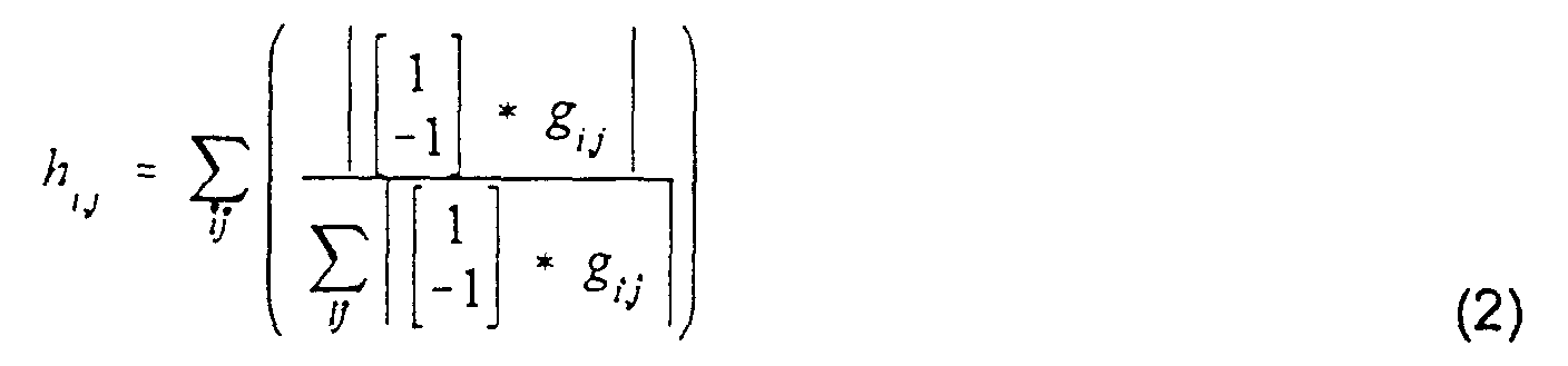
- the image metric is then calculated using this projection image and the entropy of the gradient metric F 1 .
- g ij value at image pixel located at row i and column j.
- the block of 64 views has been corrected and the next block of 64 views is selected as indicated at process block 212 and the process repeats. Otherwise, the motion estimate for this block is adjusted at process block 214 and the process is repeated to evaluate the image metric with the corresponding adjusted phase shift.
- All blocks of k-space views are separately adjusted in phase starting at the center of k-space and working outward.
- the block size is reduced in size as indicated at process block 218 and the system branches back to process block 202 to repeat the steps on the smaller block size.
- the process is repeated and the block size is reduced until the minimum block size has been processed as determined at decision block 220.
- block size is divided by two after each iteration, and the minimum block size is one view.
- the corrected k-space data set is then Fourier transformed to reconstruct an optimal image as indicated at process block 222.
- the autocorrection method can be employed on one, two or three axes of motion. In many clinical applications of the method, it has been discovered that processing only a single axis of motion is necessary. This reduces the processing time considerably. For example, if the motion is primarily along the phase encoding direction, a one dimensional FFT along the readout gradient direction can be performed once on the acquired k-space image data set before the projection and autocorrection method is applied. The phase corrections in process 204 are made on this hybrid-space data set and the Fourier transform in process 206 can be a one-dimensional FFT along the phase encoding gradient direction.
- the autocorrection method may be modified in this situation to evaluate the image metric in process block 208 only in the selected region of interest. That is, the operator identifies the pixels in the region of interest and the image metric is calculated only on these pixels. This reduces processing time and in some cases improves the resulting image in the critical region. This also enables the correction of images in which the motion is different in different regions of the image. In such cases each region may be separately corrected using the autocorrection method. Simple, non-global motions of this type can be corrected, for example, in MR angiography where the motions are not complex.
- the complete image may contain 256 columns of pixels which must be Fourier transformed each time the metric is to be calculated. If the region selected by the operator extends over only 64 columns of pixels, then only those 64 columns need be Fourier transformed during each evaluation iteration. This reduces the processing time by a factor of four.
- the present invention can also be used to correct other MR errors. For example, errors caused by gradient non-idealities in echo-planar imaging (EPI) acquisitions, or saturation variations due to variations in TR when imaging using cardiac gating can be corrected.
- EPI echo-planar imaging
- the present invention also enables the autocorrections to be applied locally rather than globally to the entire image.
- local regions in the image can be separately corrected to further reduce processing time and tailor the correction to the particular motion in that region.
- While the present invention is particularly applicable to correct projection MR angiograms, it is also applicable to other clinical MRI applications where the final image is different than the acquired image.
- many different images may be produced from acquired MR elastography image data as disclosed in U.S. Pat. Nos. 5,592,085 and 5,825,186.
- Functional MR images may be produced from acquired MR image data as described in U.S. Pat. No. 5,603,323 and diffusion weighted images may be produced from acquired MR image data as described in U.S. Pat. No. 4,609,872.
- An MRA image is corrected for motion artifacts using an iterative, autocorrection process in which corrections are tried and the quality of the resulting reconstructed image is measured. Corrections are made to the acquired three-dimensional data while the metric which measures image quality is applied to a two-dimensional projection image.
Landscapes
- Physics & Mathematics (AREA)
- Engineering & Computer Science (AREA)
- General Physics & Mathematics (AREA)
- Health & Medical Sciences (AREA)
- Theoretical Computer Science (AREA)
- Signal Processing (AREA)
- Biophysics (AREA)
- Radiology & Medical Imaging (AREA)
- General Health & Medical Sciences (AREA)
- High Energy & Nuclear Physics (AREA)
- Condensed Matter Physics & Semiconductors (AREA)
- Life Sciences & Earth Sciences (AREA)
- Nuclear Medicine, Radiotherapy & Molecular Imaging (AREA)
- Physiology (AREA)
- Cardiology (AREA)
- Power Engineering (AREA)
- Pulmonology (AREA)
- Magnetic Resonance Imaging Apparatus (AREA)
- Apparatus For Radiation Diagnosis (AREA)
Abstract
Description

Claims (12)
- A method for correcting an MRA image for artifacts, the steps comprising:a) acquiring a series of views using a magnetic resonance imaging system that performs a three-dimensional imaging pulse sequence to form a three-dimensional image data set;b) reconstructing a three-dimensional image from the acquired three-dimensional image data set;c) projecting the three-dimensional image onto a two-dimensional projection plane to form a two-dimensional projection image;d) evaluating the quality of the reconstructed image by calculating a cost function based on the two-dimensional projection image; ande) iteratively minimizing the cost function by making corrections to views in the three-dimensional image data set and repeating steps b), c), d) and e).
- The method as recited in claim 1 in which the three-dimensional image is reconstructed by performing a Fourier transformation.
- The method as recited in claim 1 in which the artifacts are caused by patient motion.
- The method as recited in claim 1 which includes selecting a region in the image which is to be corrected and performing steps c), d) and e) on the selected region.
- The method as recited in claim 4 in which only a portion of the image containing said selected region is reconstructed in step b).
- The method as recited in claim 4 which includes selecting a second region in the image which is to be corrected and performing steps c), d) and e) on the second region.
- The method as recited in claim 1 in which the cost function is calculated as the entropy of the gradient of the two-dimensional projection image.
- The method as recited in claim 1 in which the cost function is iteratively minimized in step e) by:i) making corrections to each of a plurality of blocks of views and repeating steps b), c) and d) until the cost function is minimized for each block;ii) reducing the number of views in each block and repeating step i); andiii) repeating step ii) until the number of views in the block reaches a minimum.
- The method as recited in claim 8 in which the minimum is one view per block.
- A method for correcting an image for artifacts; the steps comprising:a) acquiring a series of views using a magnetic resonance imaging system that performs an imaging pulse sequence to form a k-space image data set;b) reconstructing an image by Fourier transforming the k-space image data set;c) producing a derivative image by processing the reconstructed image;d) evaluating the quality of the derivative image by calculating a cost function based on the derivative image; ande) iteratively minimizing the cost function by making corrections to views in the k-space image data set and repeating steps b), c), d) and e).
- The method as recited in claim 10 in which the derivative image produced in step c) is non-linearly related to the reconstructed image.
- The method as recited in claim 10 in which the reconstructed image is a three-dimensional image and the derivative image is a two-dimensional projection image.
Applications Claiming Priority (2)
| Application Number | Priority Date | Filing Date | Title |
|---|---|---|---|
| US19311900P | 2000-03-30 | 2000-03-30 | |
| US193119P | 2000-03-30 |
Publications (3)
| Publication Number | Publication Date |
|---|---|
| EP1148343A2 true EP1148343A2 (en) | 2001-10-24 |
| EP1148343A3 EP1148343A3 (en) | 2004-06-02 |
| EP1148343B1 EP1148343B1 (en) | 2006-09-06 |
Family
ID=22712344
Family Applications (1)
| Application Number | Title | Priority Date | Filing Date |
|---|---|---|---|
| EP01106674A Expired - Lifetime EP1148343B1 (en) | 2000-03-30 | 2001-03-16 | Autocorrection of MR projection images for motion artifacts |
Country Status (4)
| Country | Link |
|---|---|
| US (1) | US6647134B1 (en) |
| EP (1) | EP1148343B1 (en) |
| JP (1) | JP3556176B2 (en) |
| DE (1) | DE60122818T2 (en) |
Cited By (3)
| Publication number | Priority date | Publication date | Assignee | Title |
|---|---|---|---|---|
| DE10227306A1 (en) * | 2002-06-19 | 2004-01-15 | Siemens Ag | Improving calibration parameters for three-dimensional x-ray reconstruction involves changing calibration parameters so that reconstructed volumes have very sharp edges and hence high frequencies |
| US9797974B2 (en) | 2013-01-30 | 2017-10-24 | The Board Of Trustees Of The Leland Stanford Junior University | Nonrigid motion correction in 3D using autofocusing with localized linear translations |
| US20230169704A1 (en) * | 2021-11-29 | 2023-06-01 | Canon Medical Systems Corporation | Advanced signal combination for improved overlapping image correction |
Families Citing this family (16)
| Publication number | Priority date | Publication date | Assignee | Title |
|---|---|---|---|---|
| JP2003339667A (en) * | 2002-05-31 | 2003-12-02 | National Institute Of Advanced Industrial & Technology | Ultrafast magnetic resonance imaging system |
| DE102006062763B4 (en) * | 2006-04-13 | 2009-10-22 | Charité - Universitätsmedizin Berlin | Method for magnetic resonance elastography (MRE) |
| DE102006037160B4 (en) * | 2006-04-13 | 2009-10-08 | Charité - Universitätsmedizin Berlin | Device for Magnetic Resonance Elastography (MRE) |
| DE102007006142A1 (en) * | 2007-02-07 | 2008-08-14 | Siemens Ag | Method and apparatus for automatically determining a flow of body fluid within vessels of a living being |
| US7692423B2 (en) * | 2007-10-08 | 2010-04-06 | The Board Of Trustees Of The Leland Stanford Junior University | Self navigating cartesian trajectory |
| US7595639B2 (en) * | 2008-01-15 | 2009-09-29 | General Electric Company | System and method of angular elliptic centric view ordering for 3D MR acquisitions |
| JP5572151B2 (en) * | 2008-04-04 | 2014-08-13 | メイヨ フォンデーシヨン フォー メディカル エジュケーション アンド リサーチ | Nuclear magnetic resonance elastic modulus inversion method using finite medium model |
| US8396267B2 (en) * | 2009-11-04 | 2013-03-12 | International Business Machines Corporation | Correcting subject motion in multiple resolutions in magnetic resonance imaging |
| US8639006B2 (en) | 2010-08-12 | 2014-01-28 | Viewray Incorporated | Correction of saturation banding artifacts in magnetic resonance imaging |
| US8306299B2 (en) * | 2011-03-25 | 2012-11-06 | Wisconsin Alumni Research Foundation | Method for reconstructing motion-compensated magnetic resonance images from non-Cartesian k-space data |
| DE102012217997A1 (en) * | 2012-10-02 | 2014-04-03 | Siemens Aktiengesellschaft | Method for time-dependent intensity correction of diffusion-weighted MR images and magnetic resonance system |
| US9482732B2 (en) * | 2012-11-08 | 2016-11-01 | Nicolas Chesneau | MRI reconstruction with motion-dependent regularization |
| CN104931903B (en) * | 2014-03-18 | 2018-02-02 | 上海联影医疗科技有限公司 | A kind of magnetic resonance removes the method and device of motion artifacts |
| WO2018175807A1 (en) | 2017-03-22 | 2018-09-27 | Viewray Technologies, Inc. | Reduction of artifacts in magnetic resonance imaging by creating inhomogeneity in the magnetic field at gradient null position of an mri system |
| CN109214992B (en) * | 2018-07-27 | 2022-04-05 | 中国科学院深圳先进技术研究院 | MRI image artifact removal method, device, medical equipment and storage medium |
| CN110473269B (en) * | 2019-08-08 | 2023-05-26 | 上海联影医疗科技股份有限公司 | Image reconstruction method, system, equipment and storage medium |
Family Cites Families (20)
| Publication number | Priority date | Publication date | Assignee | Title |
|---|---|---|---|---|
| US4431968A (en) * | 1982-04-05 | 1984-02-14 | General Electric Company | Method of three-dimensional NMR imaging using selective excitation |
| US4609872A (en) * | 1984-08-10 | 1986-09-02 | General Electric Company | NMR multiple-echo phase-contrast blood flow imaging |
| US4567893A (en) * | 1984-11-21 | 1986-02-04 | General Electric Company | Method of eliminating breathing artifacts in NMR imaging |
| US4665365A (en) * | 1985-01-07 | 1987-05-12 | General Electric Company | Method for reversing residual transverse magnetization due to phase-encoding magnetic field gradients |
| US4706026A (en) * | 1985-08-16 | 1987-11-10 | General Electric Company | Method for reducing image artifacts due to periodic signal variations in NMR imaging |
| US4663591A (en) * | 1985-08-16 | 1987-05-05 | General Electric Company | Method for reducing image artifacts due to periodic signal variations in NMR imaging |
| US4731583A (en) * | 1985-11-15 | 1988-03-15 | General Electric Company | Method for reduction of MR image artifacts due to flowing nuclei by gradient moment nulling |
| US4714081A (en) * | 1986-03-03 | 1987-12-22 | General Electric Company | Methods for NMR angiography |
| US4937526A (en) * | 1988-11-23 | 1990-06-26 | Mayo Foundation For Medical Education And Research | Adaptive method for reducing motion and flow artifacts in NMR images |
| JPH02215440A (en) * | 1989-02-17 | 1990-08-28 | Toshiba Corp | Magnetic resonance imaging device |
| US4992736A (en) * | 1989-08-04 | 1991-02-12 | General Electric Company | Radio frequency receiver for a NMR instrument |
| US4952877A (en) * | 1989-08-11 | 1990-08-28 | General Electric Company | RF synthesizer or an NMR instrument |
| US5204627A (en) * | 1991-03-14 | 1993-04-20 | Wisconsin Alumni Research Foundation | Adaptive NMR angiographic reprojection method |
| US5825186A (en) * | 1994-10-19 | 1998-10-20 | Mayo Foundation For Medical Education And Research | Method for producing stiffness-weighted MR images |
| US5592085A (en) * | 1994-10-19 | 1997-01-07 | Mayo Foundation For Medical Education And Research | MR imaging of synchronous spin motion and strain waves |
| US5603323A (en) * | 1996-02-27 | 1997-02-18 | Advanced Technology Laboratories, Inc. | Medical ultrasonic diagnostic system with upgradeable transducer probes and other features |
| GB9614407D0 (en) | 1996-07-09 | 1996-09-04 | Secr Defence | Method for imaging artefact reduction |
| US6263230B1 (en) * | 1997-05-08 | 2001-07-17 | Lucent Medical Systems, Inc. | System and method to determine the location and orientation of an indwelling medical device |
| DE69900416T2 (en) * | 1998-04-15 | 2002-06-06 | Mayo Foundation For Medical Education And Research, Rochester | SELF-CORRECTION OF MOVEMENT ARTIFACTS IN MAGNETIC RESONANCE IMAGES |
| US6400841B1 (en) * | 1999-02-11 | 2002-06-04 | General Electric Company | Method for evaluating three-dimensional rendering systems |
-
2000
- 2000-06-15 US US09/595,282 patent/US6647134B1/en not_active Expired - Lifetime
-
2001
- 2001-03-16 EP EP01106674A patent/EP1148343B1/en not_active Expired - Lifetime
- 2001-03-16 DE DE60122818T patent/DE60122818T2/en not_active Expired - Lifetime
- 2001-03-30 JP JP2001101091A patent/JP3556176B2/en not_active Expired - Lifetime
Cited By (4)
| Publication number | Priority date | Publication date | Assignee | Title |
|---|---|---|---|---|
| DE10227306A1 (en) * | 2002-06-19 | 2004-01-15 | Siemens Ag | Improving calibration parameters for three-dimensional x-ray reconstruction involves changing calibration parameters so that reconstructed volumes have very sharp edges and hence high frequencies |
| US9797974B2 (en) | 2013-01-30 | 2017-10-24 | The Board Of Trustees Of The Leland Stanford Junior University | Nonrigid motion correction in 3D using autofocusing with localized linear translations |
| US20230169704A1 (en) * | 2021-11-29 | 2023-06-01 | Canon Medical Systems Corporation | Advanced signal combination for improved overlapping image correction |
| US12125127B2 (en) * | 2021-11-29 | 2024-10-22 | Canon Medical Systems Corporation | Advanced signal combination for improved overlapping image correction |
Also Published As
| Publication number | Publication date |
|---|---|
| JP2001309903A (en) | 2001-11-06 |
| EP1148343A3 (en) | 2004-06-02 |
| JP3556176B2 (en) | 2004-08-18 |
| DE60122818D1 (en) | 2006-10-19 |
| US6647134B1 (en) | 2003-11-11 |
| EP1148343B1 (en) | 2006-09-06 |
| DE60122818T2 (en) | 2006-12-28 |
Similar Documents
| Publication | Publication Date | Title |
|---|---|---|
| US6647134B1 (en) | Autocorrection of MR projection images | |
| US6184682B1 (en) | Correction of MR images for motion artifacts using navigator echoes and autocorrection | |
| NL1031123C2 (en) | Method and system for MR imaging with reduced radial ripple artifacts. | |
| US6518759B2 (en) | Motion correction of magnetic resonance images | |
| US6037771A (en) | Sliding thin-slab acquisition of three-dimensional MRA data | |
| US7821264B2 (en) | System and method for MR imaging in inhomogeneous magnetic fields | |
| JP4121174B2 (en) | Method for correcting Maxwell term errors generated by a nuclear magnetic resonance system | |
| US7432706B2 (en) | Magnetic resonance imaging using blood flow navigation | |
| JP2004527301A (en) | Method of acquiring MRI data from a large field of view using continuous table movement | |
| US6307369B1 (en) | Autocorrection of 3D MR images for motion artifacts | |
| JP2005503874A (en) | Magnetic resonance angiography using floating table projection imaging | |
| US6924643B2 (en) | Magnetic resonance imaging using direct, continuous real-time imaging for motion compensation | |
| US5729140A (en) | Suppression of artifacts in NMR images by correlation of two NEX acquistions | |
| EP1139114A2 (en) | Slice ordering method for breath-hold abdominal MR imaging | |
| EP1072019B1 (en) | Autocorrection of mr images for motion artifacts | |
| WO2007050698A2 (en) | Parallel magnetic resonance imaging method using a radial acquisition trajectory | |
| CN112394311B (en) | MRI system with improved navigator | |
| EP1372110B1 (en) | Method and system for image reconstruction | |
| US6975113B1 (en) | Method and system for moving table MRI with partial fourier imaging | |
| JPH11276458A (en) | Method and apparatus for acquiring heartbeat phase images | |
| US7706855B1 (en) | System and method for MR data acquisition with uniform fat suppression | |
| US6469506B1 (en) | Autocorrection of MR images acquired using phased-array coils | |
| US6265874B1 (en) | Autocorrection of MR images using multiple metrics | |
| US6100689A (en) | Method for quantifying ghost artifacts in MR images | |
| CN117849684A (en) | Silent calibration for magnetic resonance imaging |
Legal Events
| Date | Code | Title | Description |
|---|---|---|---|
| PUAI | Public reference made under article 153(3) epc to a published international application that has entered the european phase |
Free format text: ORIGINAL CODE: 0009012 |
|
| AK | Designated contracting states |
Kind code of ref document: A2 Designated state(s): AT BE CH CY DE DK ES FI FR GB GR IE IT LI LU MC NL PT SE TR |
|
| AX | Request for extension of the european patent |
Free format text: AL;LT;LV;MK;RO;SI |
|
| PUAL | Search report despatched |
Free format text: ORIGINAL CODE: 0009013 |
|
| RIC1 | Information provided on ipc code assigned before grant |
Ipc: 7G 06T 11/00 B Ipc: 7G 06T 5/00 B Ipc: 7G 01R 33/565 B Ipc: 7G 01R 33/563 A |
|
| AK | Designated contracting states |
Kind code of ref document: A3 Designated state(s): AT BE CH CY DE DK ES FI FR GB GR IE IT LI LU MC NL PT SE TR |
|
| AX | Request for extension of the european patent |
Extension state: AL LT LV MK RO SI |
|
| 17P | Request for examination filed |
Effective date: 20040817 |
|
| AKX | Designation fees paid |
Designated state(s): DE GB NL |
|
| GRAP | Despatch of communication of intention to grant a patent |
Free format text: ORIGINAL CODE: EPIDOSNIGR1 |
|
| GRAS | Grant fee paid |
Free format text: ORIGINAL CODE: EPIDOSNIGR3 |
|
| GRAA | (expected) grant |
Free format text: ORIGINAL CODE: 0009210 |
|
| AK | Designated contracting states |
Kind code of ref document: B1 Designated state(s): DE GB NL |
|
| REG | Reference to a national code |
Ref country code: GB Ref legal event code: FG4D |
|
| REF | Corresponds to: |
Ref document number: 60122818 Country of ref document: DE Date of ref document: 20061019 Kind code of ref document: P |
|
| RIN2 | Information on inventor provided after grant (corrected) |
Inventor name: MANDUCA, ARMANDO Inventor name: MCGEE, KIARAN, P. Inventor name: FELMLEE, JOEL Inventor name: EHMAN, RICHARD |
|
| PLBE | No opposition filed within time limit |
Free format text: ORIGINAL CODE: 0009261 |
|
| STAA | Information on the status of an ep patent application or granted ep patent |
Free format text: STATUS: NO OPPOSITION FILED WITHIN TIME LIMIT |
|
| 26N | No opposition filed |
Effective date: 20070607 |
|
| REG | Reference to a national code |
Ref country code: DE Ref legal event code: R082 Ref document number: 60122818 Country of ref document: DE Representative=s name: ADVOTEC. PATENT- UND RECHTSANWAELTE, DE |
|
| PGFP | Annual fee paid to national office [announced via postgrant information from national office to epo] |
Ref country code: DE Payment date: 20200327 Year of fee payment: 20 Ref country code: NL Payment date: 20200326 Year of fee payment: 20 Ref country code: GB Payment date: 20200327 Year of fee payment: 20 |
|
| REG | Reference to a national code |
Ref country code: DE Ref legal event code: R071 Ref document number: 60122818 Country of ref document: DE |
|
| REG | Reference to a national code |
Ref country code: NL Ref legal event code: MK Effective date: 20210315 |
|
| REG | Reference to a national code |
Ref country code: GB Ref legal event code: PE20 Expiry date: 20210315 |
|
| PG25 | Lapsed in a contracting state [announced via postgrant information from national office to epo] |
Ref country code: GB Free format text: LAPSE BECAUSE OF EXPIRATION OF PROTECTION Effective date: 20210315 |