EP1148342A2 - Method for measurement of magnetic fields, method for production of gradient coils, gradient coil, and apparatus for magnetic resonance imaging - Google Patents
Method for measurement of magnetic fields, method for production of gradient coils, gradient coil, and apparatus for magnetic resonance imaging Download PDFInfo
- Publication number
- EP1148342A2 EP1148342A2 EP01303473A EP01303473A EP1148342A2 EP 1148342 A2 EP1148342 A2 EP 1148342A2 EP 01303473 A EP01303473 A EP 01303473A EP 01303473 A EP01303473 A EP 01303473A EP 1148342 A2 EP1148342 A2 EP 1148342A2
- Authority
- EP
- European Patent Office
- Prior art keywords
- magnetic field
- gradient
- coil
- measuring
- measurement
- Prior art date
- Legal status (The legal status is an assumption and is not a legal conclusion. Google has not performed a legal analysis and makes no representation as to the accuracy of the status listed.)
- Withdrawn
Links
Images






Classifications
-
- A—HUMAN NECESSITIES
- A61—MEDICAL OR VETERINARY SCIENCE; HYGIENE
- A61B—DIAGNOSIS; SURGERY; IDENTIFICATION
- A61B5/00—Measuring for diagnostic purposes; Identification of persons
- A61B5/05—Detecting, measuring or recording for diagnosis by means of electric currents or magnetic fields; Measuring using microwaves or radio waves
- A61B5/055—Detecting, measuring or recording for diagnosis by means of electric currents or magnetic fields; Measuring using microwaves or radio waves involving electronic [EMR] or nuclear [NMR] magnetic resonance, e.g. magnetic resonance imaging
-
- G—PHYSICS
- G01—MEASURING; TESTING
- G01R—MEASURING ELECTRIC VARIABLES; MEASURING MAGNETIC VARIABLES
- G01R33/00—Arrangements or instruments for measuring magnetic variables
- G01R33/20—Arrangements or instruments for measuring magnetic variables involving magnetic resonance
- G01R33/44—Arrangements or instruments for measuring magnetic variables involving magnetic resonance using nuclear magnetic resonance [NMR]
- G01R33/48—NMR imaging systems
- G01R33/54—Signal processing systems, e.g. using pulse sequences ; Generation or control of pulse sequences; Operator console
- G01R33/56—Image enhancement or correction, e.g. subtraction or averaging techniques, e.g. improvement of signal-to-noise ratio and resolution
- G01R33/565—Correction of image distortions, e.g. due to magnetic field inhomogeneities
- G01R33/56518—Correction of image distortions, e.g. due to magnetic field inhomogeneities due to eddy currents, e.g. caused by switching of the gradient magnetic field
Definitions
- the present invention relates to a method for measurement of magnetic fields, a method for production of gradient coils, a gradient coil and an apparatus for magnetic resonance imaging, and more particularly to a method for measuring, after stopping application of a gradient magnetic field, the residual magnetic field; a gradient coil whose higher term of residual magnetic field is smaller; a manufacturing method for the same; and an apparatus for magnetic resonance imaging having such a gradient coil.
- a subject of imaging is brought into the bore of a magnet system, i.e. a space in which a magnetostatic field is formed, to generate magnetic resonance signals in the subject by applying gradient magnetic fields and high frequency magnetic fields, and sectional images are generated (reconstructed) on the basis of received magnetic resonance signals.
- a magnet system i.e. a space in which a magnetostatic field is formed
- a pole piece for uniformizing the magnetic flux distribution in the magnetostatic field space is provided at the tip of each of paired permanent magnets opposite to each other, and a gradient coil for generating gradient magnetic fields is provided along the pole face of each such pole piece.
- the present invention seeks to realize a method for measuring, after stopping application of gradient magnetic fields, the residual magnetic fields; a method for manufacturing a gradient coil by causing the characteristics of the residual magnetic fields, revealed by the measurement, to be reflected in it; a gradient coil manufactured by that method; and an apparatus for magnetic resonance imaging having such a gradient coil.
- the invention from one point of view is a method for measurement of magnetic fields characterized in that a magnetically resonant sample is arranged at a measuring point on the surface of an imaginary sphere in a measuring space; a gradient magnetic field is applied to the measuring space; RF excitation is carried out after stopping the application of the gradient magnetic field to measure FID signals generated by the sample; the magnetic field intensity is calculated on the basis of a difference in differentials of the phases of the FID signals; and a magnetic field intensity is fitted into a spheric surface function representing a magnetic field intensity distribution in the measuring space.
- a spheric surface function representing the characteristics of the residual magnetic field is identified by measuring the magnetic field in which residual magnetization arises by utilizing FID signals from a sample arranged at a measuring point on a spheric surface and fitting the measurement into the spheric surface function.
- the invention from another point of view is a method for measurement of magnetic fields characterized in that a magnetically resonant sample is arranged at a measuring point on the surface of an imaginary sphere in a measuring space; another magnetically resonant sample is arranged at the center of the sphere; a gradient magnetic field is applied to the measuring space; RF excitation is carried out after stopping the application of the gradient magnetic field to measure FID signals generated by the samples; a magnetic field intensity at the measuring point is calculated on the basis of a difference in differentials of the phases of FID signals generated by the samples at the measuring point and at the center of the sphere; and the magnetic field intensity is fitted into a spheric surface function representing a magnetic field intensity distribution in the measuring space.
- FID signals from a sample arranged at the center of the sphere are measured and used as reference.
- the invention from still another point of view is a method for measurement of magnetic fields characterized in that: a magnetically resonant sample is arranged at a measuring point on the surface of an imaginary sphere in a measuring space; a gradient magnetic field is intermittently applied while the gradient is successively varied from the maximum gradient in one polarity to the maximum gradient in the reverse polarity and then the gradient is successively varied from the maximum gradient in the reverse polarity to the maximum gradient in the first polarity; RF excitation is carried out during the intermittence of the gradient magnetic field to measure FID signals generated by the sample; differentials of the phases of the FID signals are calculated; a magnetic field intensity at the measuring point is calculated on the basis of the hysteresis of differences in the differentials accompanying the completion of the round of gradients; and the magnetic field intensity is fitted into a spheric surface function representing a magnetic field intensity distribution in the measuring space.
- the gradient magnetic field is varied reciprocatingly between the maximum gradient in one polarity and the maximum gradient in the reverse polarity. This makes possible magnetic field measurement with the hysteresis of residual magnetization kept constant.
- the invention from still another point of view is a method for measurement of magnetic fields characterized in that: a magnetically resonant sample is arranged at a measuring point on the surface of an imaginary sphere in a measuring space; another magnetically resonant sample is arranged at the center of the sphere; a gradient magnetic field is intermittently applied while the gradient is successively varied from the maximum gradient in one polarity to the maximum gradient in the reverse polarity and then the gradient is successively varied from the maximum gradient in the reverse polarity to the maximum gradient in the first polarity; RF excitation is carried out during the intermittence of the gradient magnetic field to measure FID signals generated by the samples; differences in differentials of the phases of FID signals generated by the samples at the measuring point and at the center of the sphere are calculated; a magnetic field intensity at the measuring point is calculated on the basis of the hysteresis of the differences in the differentials accompanying the completion of the round of gradients; and the magnetic field intensity is fitted into
- FID signals from a sample arranged at the center of the sphere are measured and used as reference.
- the invention from still another point of view is the method for measurement of magnetic fields, according to any of (1) through (4), characterized in that: the measurement is consecutively accomplished at a plurality of measuring points.
- the same sample can be used repeatedly because measurement is done consecutively at a plurality of measuring points.
- the invention from still another point of view is a method for production of gradient coils characterized in that, in producing a gradient coil: a magnetic field to be generated by the gradient coil on the surface of an imaginary sphere in a space is calculated; the magnetic field, is fitted into a spheric surface function; and the current pass of the coil is determined so as to keep small, out of high order terms in the spheric surface function into which the fitting has been carried out, a high order term corresponding to the highest order term in the spheric surface function representing the magnetic field measured by a method according to any of (1) through (5).
- a gradient coil which generates less affecting residual magnetization can be produced because the current pass of the gradient coil is determined so as to keep small a high order term corresponding to the highest order term of the residual magnetic field revealed by measurement.
- the invention from still another point of view is a gradient coil for generating a gradient magnetic field with a current flowing through a current pass, the gradient coil being characterized in that the current pass is determined by the following procedure:
- the invention from this point of view results in a gradient coil which generates less affecting residual magnetization can be produced because the current pass of the gradient coil is determined so as to keep small a high order term corresponding to the highest order term of the residual magnetic field revealed by measurement.
- the invention from still another point of view is an apparatus for magnetic resonance imaging for structuring an image on the basis of magnetic resonance signals acquired by using a magnetostatic field, gradient magnetic fields and high frequency magnetic fields, the apparatus for magnetic resonance imaging being characterized in that, it is provided with, as a gradient coil for generating the gradient magnetic field, a gradient coil having a current pass determined by the following procedure:
- appropriate magnetic resonance imaging can be accomplished using a gradient coil which generates less affecting residual magnetization because the current pass of the gradient coil is determined so as to keep small a high order term corresponding to the highest order term of the residual magnetic field revealed by measurement.
- the present invention makes it possible to realize a method for measuring, after stopping application of gradient magnetic fields, the residual magnetic fields; a method for manufacturing gradient coils reflecting the characteristics of residual magnetic fields revealed by the measurement; a gradient coil manufactured by the method; and an apparatus for magnetic resonance imaging having such gradient coils.
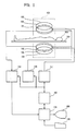
- FIG. 1 is a block diagram illustrating an apparatus for magnetic resonance imaging.
- This apparatus is an example of mode of implementing the invention.
- the configuration of this apparatus presents an example of mode of implementing the invention regarding the apparatus.
- the operation of this apparatus illustrates an example of mode of implementing the invention regarding the method.
- this apparatus has a magnet system 100.
- the magnet system 100 has main magnetic field magnet sections 102, gradient coil sections 106 and radio frequency (RF) coil sections 108. These main magnetic field magnet sections 102 and coil sections are paired opposite units having a space in-between. All the pairs are substantially disk shaped, arranged around a shared central axis.
- a subject 300, mounted on a cradle 500 is carried by a carrying means not shown in and out of the bore of the magnet system 100.
- the main magnetic field magnet sections 102 generate a magnetostatic field in the bore of the magnet system 100.
- the direction of the magnetostatic field is substantially orthogonal to the bodily axis of the subject 300.
- a so-called vertical magnetic field is formed.
- Each main magnetic field magnet section 102 is constituted of, for instance, a permanent magnet. Of course, it may be constituted of a superconductive electromagnet, a conducting electromagnet or the like instead of a permanent magnet.
- the gradient coil section 106 generates gradient magnetic fields for providing a gradient to the magnetostatic field. Three kinds of gradient magnetic fields are generated, including slice gradient magnetic fields, read out gradient magnetic fields and phase encode gradient magnetic fields. To match these three kinds of gradient magnetic fields, the gradient coil section 106 has three lines of gradient coils not shown.
- the three lines of gradient coils generate three gradient magnetic fields for providing gradients to the magnetostatic field in three mutually orthogonal directions.
- One of the three directions is the direction of the magnetostatic field (vertical direction), which usually is supposed to be the z direction.
- the remaining one is the direction normal to the z and y directions, which usually is supposed to be the x direction.
- the x direction is normal to the z direction within the vertical plane, and normal to the y direction within the horizontal plane.
- the x, y and z directions will be hereinafter referred to as gradient axes.
- any of the x, y and z axes can be used as the slice gradient axis. Where any one of them is used as the slice gradient axis, one of the remaining two is used as the phase encode gradient axis, and the other as the read out gradient axis.
- the three lines of gradient coils will be further described afterwards.
- the RF coil section 108 transmits to the magnetostatic field space RF excitation signals for exciting spins within the body of the subject 300.
- the RF coil section 108 also receives magnetic resonance signals generated by the excited spins.
- the RF coil section 108 has a coil for transmission and a coil for reception, neither shown. For transmission and reception, either the same coil may be used in common or a separate coil may be dedicated for each purpose.
- the gradient drive section 130 gives a drive signal to the gradient coil section 106 to generate gradient magnetic fields.
- the gradient drive section 130 has three lines of drive circuits respectively corresponding to the three lines of gradient coils in the gradient coil section 106.
- the RF drive section 140 gives a drive signal to the RF coil section 108 to transmit RF excitation signals and thereby to excite spins within the body of the subject 300.
- the data collecting section 150 takes in receive signals received by the RF coil section 108, and collects them as view data.
- a control section 160 is connected to the gradient drive section 130, the RF drive section 140 and the data collecting section 150.
- the control section 160 accomplishes imaging by controlling the sections from the gradient drive section 130 through the data collecting section 150.
- the output side of the data collecting section 150 is connected to a data processing section 170.
- the data processing section 170 is constituted of, for instance, a computer.
- the data processing section 170 has a memory not shown.
- the memory stores programs and various data for the data processing section 170.
- the functions of this apparatus are realized by the execution of the programs stored in the memory by the data processing section 170.
- the data processing section 170 stores into the memory the data taken in from the data collecting section 150.
- a data space is formed within the memory.
- the data space constitutes a two-dimensional Fourier space.
- the data processing section 170 subjects these data in the two-dimensional Fourier space to two-dimensional inverse Fourier transformation to generate (reconstruct) images of the subject 300.
- the two-dimensional Fourier space is also known as a k-space.
- the data processing section 170 is connected to the control section 160.
- the data processing section 170 is positioned superior to and exercises overall supervision over the control section 160.
- To the data processing section 170 are also connected a display section 180 and an operating section 190.
- the display section 180 is constituted of a graphic display or the like.
- the operating section 190 is constituted of a keyboard or the like provided with a pointing device.
- the display section 180 displays reconstructed images and various items of information outputted from the data processing section 170.
- the operating section 190 operated by an operator, inputs various commands and information to the data processing section 170. The operator operates this apparatus interactively through the display section 180 and the operating section 190.
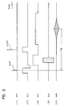
- Fig. 2 illustrates an example of set of pulse sequences for use in imaging with this apparatus.
- These pulse sequences are pulse sequences by a gradient echo (GRE) method.
- GRE gradient echo
- (1) is an ⁇ ° pulse sequence for RF excitation in the GRE process
- (2), (3), (4) and (5) are the sequences of the slice gradient Gs, the read out gradient Gr, the phase encode gradient Gp and the gradient echo MR, respectively.
- the ⁇ ° pulse is represented by the center signal.
- the pulse sequences proceed from left to right along a time axis t.
- ⁇ ° excitation of a spin with the ⁇ ° pulse is carried out.
- the flip angle ⁇ ° is not more than 90°.
- the slice gradient Gs is applied to accomplish selective excitation for a prescribed slice.
- the spin is phase-encoded with the phase encode gradient GP.
- the spin is first dephased with the read out gradient Gr, and then rephased to generate a gradient echo MR.
- the signal intensity of the gradient echo MR reaches its maximum at a point of time after the lapse of an echo time TE from the ⁇ ° excitation.
- the gradient echo MR is collected from the data collecting section 150 as view data.
- Such pulse sequences are repeated 64 to 512 times with a period of TR (repetition time).
- TR repetition time
- the phase encode gradient GP is altered to carry out phase encoding in a different way.
- view data for 64 to 512 views to fill the k-space are obtained.
- pulse sequences for magnetic resonance imaging is shown in Fig. 3. These pulse sequences are pulse sequences of a spin echo method.
- (1) is a 90° and 180° pulse sequence for RF excitation in the SE process
- (2), (3), (4) and (5) are the sequences of the slice gradient Gs, the read out gradient Gr, the phase encode gradient Gp and the spin echo MR, respectively.
- the 90° and 180° pulses are represented by the respective center signals.
- the pulse sequences proceed from left to right along a time axis t.
- 90° excitation of a spin with the 90° pulse is carried out.
- the slice gradient Gs is applied to accomplish selective excitation for a prescribed slice.
- a prescribed length of time after the 90° excitation, 180° excitation with a 180° pulse, i.e. spin inversion, is carried out.
- the slice gradient Gs is applied to accomplish selective inversion for the same slice.
- the read out gradient Gr and the phase encode gradient GP are applied.
- Spin dephasing is carried out with the read out gradient Gr.
- Spin phase encoding is accomplished with the phase encode gradient GP.
- a spin echo MR is generated by rephasing the spin with the read out gradient Gr.
- the signal intensity of the spin echo MR reaches its maximum at a point of time TE after the 90° excitation.
- the spin echo MR is collected from the data collecting section 150 as view data.
- Such pulse sequences are repeated 64 to 512 times with a period of TR (repetition time). Every time they are repeated, the phase encode gradient GP is altered to carry out phase encoding in a different way. As a result, view data for 64 to 512 views to fill the k-space are obtained.
- the pulse sequences for use in imaging are not limited to those of the GRE method or the SE method, but those of some other appropriate techniques including a fast spin echo (FSE) method, a fast recovery spin echo (FSE) method and an echo planar imaging (EPI) method may be used instead.
- FSE fast spin echo
- FSE fast recovery spin echo
- EPI echo planar imaging
- the data processing section 170 reconstructs the sectional images of the subject 300 by subjecting view data in the k-space to two-dimensional inverse Fourier conversion.
- the reconstructed images are stored in the memory, and displayed on the display section 180.
- Fig. 4 schematically illustrates a section of the structure of the magnet system 100 in the vicinity of the gradient coil section 106.
- O denotes the center of the magnetostatic field, i.e. the magnet center
- x, y and z denote the aforementioned three directions.
- a spheric volume (SV) of a radius R around the magnet center O is the area to be imaged, and the magnet system 100 is so constituted that the magnetostatic field and the gradient magnetic fields have a prescribed level of accuracy in this SV.
- the pair of main magnetic field magnet sections 102 have a pair of pole pieces 202 opposite to each other.
- the pole piece 202 is constituted of a magnetic material having a high permeability, such as soft iron, and serves to uniformize the magnetic flux distribution in the magnetostatic field space.
- Each pole piece 202 having a substantially disk shape, has a periphery projecting in a direction normal to the plate surface (the z direction); thus, the pole pieces 202, project toward each other.
- the projecting parts serve to compensate for a drop in magnetic flux density on the peripheries of the pole pieces 202.
- each pole piece 202 In a concave part, formed within the projecting portion of the periphery, of each pole piece 202, there is provided the gradient coil section 106.
- the gradient coil section 106 has an X coil 204, a Y coil 206 and a Z coil 208.
- Each of the X coil 204, the Y coil 206 and the Z coil 208 is an example of gradient coil in a mode of implementing the invention.
- the coils, formed in a substantially disk shape, are fitted to the pole face of each pole piece 202 by an appropriate fitting means not shown so as to form layers one over another.
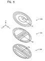
- Fig. 5 briefly illustrates the patterns of the current passes of the X coil 204, the Y coil 206 and the Z coil 208.
- the X coil 204 has, in a part near the center of the circle, a plurality of linear main passes parallel to the y direction. These main passes are symmetrical with respect to the y axis passing the center of the circle.
- the return passes of the main passes are formed along the circumference.
- the radius of the outermost return pass, i.e. the external radius of the X coil 204, is r00.
- the Y coil 206 in a part near the center of the circle, a plurality of linear main passes parallel to the x direction. These main passes are symmetrical with respect to the x axis. The return passes of the main passes are formed along the circumference.
- the radius of the outermost return pass, i.e. the external radius of the Y coil 206, is r00.
- the Z coil 208 has a plurality of current passes constituting coaxial circles. All these current passes are main passes.
- the radiuses of the main passes are, in the outward order, respectively r1, r2, ..., rM; rM is the external diameter of the Z coil 208.
- a method to measure the imaging area, i.e. residual magnetic fields in the spheric volume SV in such a magnet system 100 will be described below.
- a plurality of measuring points are set on the surface of the spheric volume SV.
- setting of a plurality of measuring points is accomplished by setting a plurality of combinations of angles ⁇ and ⁇ with the radius r being constant.
- the angle ⁇ corresponds to, so to speak, the latitude, and the angle ⁇ , to the longitude.
- the angle ⁇ as shown in Fig. 7(a), is set at, for instance, 22.5 degree intervals. Seven latitudes are set thereby.
- the angle ⁇ as shown in Fig. 7(b), is set at, for instance, 30 degree intervals. Twelve longitudes are set thereby.
- measuring points P The intersection points between such latitudes and longitudes are used as measuring points P. Therefore, the number of measuring points on the spheric surface is 84.
- a measuring point P0 is also set at the magnet center O. The measuring point P0 is for reference. If no reference is required, the measuring point P0 is dispensable.
- a probe consisting of a sample for generating magnetic resonance fitted with an RF coil for signal detection.
- a sample for instance, an aqueous solution of cupric sulfate (CuSO 4 ), nickel chloride (NiCI) or the like sealed in a small container.
- the volume of the sample is to be equivalent to one voxel of imaging space.
- Such probes are successively positioned for the measuring points to measure the magnetic field at each measuring point on the spheric surface and the magnet center O. At least two probes are used to simultaneously measure the magnetic field at each measuring point on the spheric surface and the magnet center O. If no reference is required, only the measuring points on the spheric surface are measured.
- Fig. 8 illustrates pulse sequences for measuring magnetic fields.
- (1) is the sequence of gradient magnetic fields
- (2) the sequence of RF excitation
- a gradient magnetic field G is applied to one axis and, after its completion, RF excitation is carried out.
- the sample in the probe On the basis of the RF excitation, the sample in the probe generates an FID signal.
- This FID signal is received by the RF coil provided for the probe, and received data are collected by the data collecting section 150.
- the gradient magnetic field G is like, for instance, what is represented by the solid line in Fig. 9, magnetization of the pole piece 202 thereby will leave a residual magnetic field like, for instance, what is represented by the one dot chain line even after the application of the gradient magnetic field is stopped. As represented by the shaded part in Fig. 8, the state looks as if the gradient magnetic field remained.
- An FID signal measured under such a residual magnetic field can be represented by the following mathematical expression. S ( t ) ⁇ ( r 0 )exp(- j ⁇ Grmr 0 t ) where
- the magnetic field intensity Grm affects the phase of the FID signal.
- the differential of the phase ⁇ 0(t) of the FID signal measured at the magnet center O is calculated to obtain the magnetic field intensity.
- magnetization hysteresis has arisen in the pole pieces 202.
- the magnetization hysteresis draws a minor hysteresis loop.
- magnetic field measurement is accomplished in the following manner.
- Fig. 10 illustrates the sequence of gradient magnetic field application per measuring point at the time of measurement.
- the gradient magnetic field is intermittently applied while its intensity is successively varied.
- the intensity is successively varied from -Gmax, the maximum negative gradient that can be generated by this apparatus to +Gmax, the maximum positive gradient
- the intensity is successively varied from +Gmax, the maximum positive gradient to -Gmax, the maximum negative gradient.
- a gradient magnetic field remains.
- the aforementioned RF excitation and FID measurement are performed every time and, on the basis of the measurement signal at each time, the magnetic field intensity Grm of each is found out as described above. This gives, for instance, 15 magnetic field measurements per measuring point.
- a hysteresis loop like the one shown in Fig. 11, for instance, is obtained. Then the width of this hysteresis loop in the direction of the Grm axis, i.e. the difference between values at two points on the Grm axis where the hysteresis loop crosses is supposed to be the magnetic field intensity Br(k) of the measuring point P.
- the magnetic field measurement may be referred to as simply the measurement.
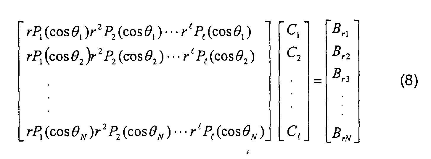
- Fitting is accomplished, for instance, in the following manner.
- C 1 ,C 2 , ⁇ ,C l components are obtained. They are usually known as Z 1 ,Z 2 , ⁇ ,Z l components.
- a 1 / 1, A 1 / 2, ⁇ , A 1 / l are obtained. They are usually known as ZX , Z 2 X , ⁇
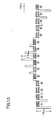
- Fig. 12 shows a flow chart of magnetic field measurement at a plurality of measuring points as described above and fitting into the spheric surface function on that basis.
- measuring points on the spherical surface are set at step 702.
- the measuring points are set in the manner described above.
- probes are set, one each at the center or the sphere, i.e. the magnet center O, and at one measuring point on the spherical surface.
- a measuring sequence as shown in Fig. 10 is executed to measure the FID signals of the two probes, and the magnetic field measurement Grm is calculated on the basis of the difference between the differentials of their phases.
- a residual magnetic field Br(k) is calculated on the basis of the hysteresis of Grm as shown in Fig. 11.
- step 710 it is determined whether or not the residual magnetic field Br(k) has been calculated for every measuring point and, if not, the measuring point is altered at step 712 to repeat the operations at steps 706 and 708.
- Fig. 13 is a flow chart showing an example of the procedure of gradient coil designing, which reflects the result of residual magnetic field analysis. Here is shown the designing procedure for the Z coil.
- the initial values of the radiuses r1, r2, ..., rM of the current passes of the Z coil are set at step 902.
- step 908 where the above-described analysis of residual magnetic fields has revealed, in particular, that the Z N term is greater, to make min( Z N ( r )) ⁇ ⁇ hold true, r is adjusted, where ⁇ is an allowance.
- step 910 it is determined whether or not the magnetic field generated by the Z coil satisfying the above-stated conditions and adjusted to satisfy them satisfies a prescribed degree of linearity.
- step 912 by a nonlinear programming method r is newly set, and the processing from step 904 onward is repeated.
Landscapes
- Physics & Mathematics (AREA)
- Health & Medical Sciences (AREA)
- Nuclear Medicine, Radiotherapy & Molecular Imaging (AREA)
- Life Sciences & Earth Sciences (AREA)
- General Health & Medical Sciences (AREA)
- Radiology & Medical Imaging (AREA)
- Engineering & Computer Science (AREA)
- High Energy & Nuclear Physics (AREA)
- Signal Processing (AREA)
- General Physics & Mathematics (AREA)
- Condensed Matter Physics & Semiconductors (AREA)
- Medical Informatics (AREA)
- Pathology (AREA)
- Biomedical Technology (AREA)
- Heart & Thoracic Surgery (AREA)
- Biophysics (AREA)
- Molecular Biology (AREA)
- Surgery (AREA)
- Animal Behavior & Ethology (AREA)
- Public Health (AREA)
- Veterinary Medicine (AREA)
- Magnetic Resonance Imaging Apparatus (AREA)
Abstract
Description







Claims (8)
- A method for measurement of magnetic fields comprising the steps of:arranging a magnetically resonant sample at a measuring point on the surface of an imaginary sphere in a measuring space;applying a gradient magnetic field to said measuring space;carrying out RF excitation after stopping the application of said gradient magnetic field to measure FID signals generated by said sample;calculating a magnetic field intensity at said measuring point on the basis of differentials of the phases of said FID signals; andfitting said magnetic field intensity into a spheric surface function representing a magnetic field intensity distribution in said measuring space.
- A method for measurement of magnetic fields comprising the steps of:arranging a magnetically resonant sample at a measuring point on the surface of an imaginary sphere in a measuring space;arranging another magnetically resonant sample at the center of said sphere;applying a gradient magnetic field to said measuring space;carrying out RF excitation after stopping the application of said gradient magnetic field to measure FID signals generated by said samples;calculating a magnetic field intensity at said measuring point on the basis of differences in differentials of the phases of FID signals generated by the samples at said measuring point and at the center of said sphere; andfitting said magnetic field intensity into a spheric surface function representing a magnetic field intensity distribution in said measuring space.
- A method for measurement of magnetic fields comprising the steps of:arranging a magnetically resonant sample at a measuring point on the surface of an imaginary sphere in a measuring space;applying intermittently a gradient magnetic field while the gradient is successively varied from the maximum gradient in one polarity to the maximum gradient in the reverse polarity and then the gradient is successively varied from the maximum gradient in said reverse polarity to the maximum gradient in said first polarity;carrying out RF excitation during the intermittence of said gradient magnetic field to measure FID signals generated by said sample;calculating differentials of the phases of said FID signals;calculating a magnetic field intensity at said measuring point on the basis of the hysteresis of differences in said differentials accompanying the completion of said round of gradients; andfitting said magnetic field intensity into a spheric surface function representing a magnetic field intensity distribution in said measuring space.
- A method for measurement of magnetic fields comprising the steps of:arranging a magnetically resonant sample at a measuring point on the surface of an imaginary sphere in a measuring space;arranging another magnetically resonant sample at the center of said sphere;applying intermittently a gradient magnetic field while the gradient is successively varied from the maximum gradient in one polarity to the maximum gradient in the reverse polarity and then the gradient is successively varied from the maximum gradient in said reverse polarity to the maximum gradient in said first polarity;carrying out RF excitation during the intermittence of said gradient magnetic field to measure FID signals generated by said samples;calculating differences in differentials of the phases of FID signals generated by the samples at said measuring point and at the center of said sphere;calculating a magnetic field intensity at said measuring point on the basis of the hysteresis of the differences in said differentials accompanying the completion of said round of gradients; andfitting said magnetic field intensity into a spheric surface function representing a magnetic field intensity distribution in said measuring space.
- The method for measurement of magnetic fields, according to any of Claims 1 to 4, wherein said measurement is consecutively accomplished at a plurality of measuring points.
- A method for production of gradient coils comprising the steps of, in producing a gradient coil:calculating a magnetic field to be generated by said gradient coil on the surface of an imaginary sphere in a space;fitting said magnetic field into a spheric surface function; anddetermining the current pass of the coil so as to keep small, out of high order terms in the spheric surface function into which said fitting has been carried out, a high order term corresponding to the highest order term in the spheric surface function representing the magnetic field measured by a method according to any one of Claims 1 to 4.
- A gradient coil for generating a gradient magnetic field with a current flowing through a current pass,
said current pass is determined by the following procedure:(a) a magnetic field to be generated by said gradient coil on the surface of an imaginary sphere in a space is calculated;(b) said magnetic field is fitted into a spheric surface function; and(c) the current pass of the coil is determined so as to keep small, out of high order terms in the spheric surface function into which said fitting has been carried out, a high order term corresponding to the highest order term in the spheric surface function representing the magnetic field measured by a method according to any one of Claims 1 to 4. - An apparatus for magnetic resonance imaging for structuring an image on the basis of magnetic resonance signals acquired by using a magnetostatic field, gradient magnetic fields and high frequency magnetic fields,
it is provided with, as a gradient coil for generating said gradient magnetic field, a gradient coil having a current pass determined by the following procedure:(a) a magnetic field to be generated by said gradient coil on the surface of an imaginary sphere in a space is calculated;(b) said magnetic field is fitted into a spheric surface function; and(c) the current pass of the coil is determined so as to keep small, out of high order terms in the spheric surface function into which said fitting has been carried out, a high order term corresponding to the highest order term in the spheric surface function representing the magnetic field measured by a method according to any one of Claim 1 through Claim 4.
Applications Claiming Priority (2)
| Application Number | Priority Date | Filing Date | Title |
|---|---|---|---|
| JP2000117880A JP3701540B2 (en) | 2000-04-19 | 2000-04-19 | Magnetic field measurement method, gradient coil manufacturing method, gradient coil, and magnetic resonance imaging apparatus |
| JP2000117880 | 2000-04-19 |
Publications (2)
| Publication Number | Publication Date |
|---|---|
| EP1148342A2 true EP1148342A2 (en) | 2001-10-24 |
| EP1148342A3 EP1148342A3 (en) | 2003-09-03 |
Family
ID=18629122
Family Applications (1)
| Application Number | Title | Priority Date | Filing Date |
|---|---|---|---|
| EP01303473A Withdrawn EP1148342A3 (en) | 2000-04-19 | 2001-04-12 | Method for measurement of magnetic fields, method for production of gradient coils, gradient coil, and apparatus for magnetic resonance imaging |
Country Status (5)
| Country | Link |
|---|---|
| US (1) | US6813513B2 (en) |
| EP (1) | EP1148342A3 (en) |
| JP (1) | JP3701540B2 (en) |
| KR (1) | KR100458771B1 (en) |
| CN (1) | CN1336558A (en) |
Cited By (1)
| Publication number | Priority date | Publication date | Assignee | Title |
|---|---|---|---|---|
| CN109598004A (en) * | 2017-09-30 | 2019-04-09 | 中国科学院长春光学精密机械与物理研究所 | Horizontal gradient loop and its design method for minute yardstick magnetic resonance imaging system |
Families Citing this family (20)
| Publication number | Priority date | Publication date | Assignee | Title |
|---|---|---|---|---|
| US7603156B2 (en) * | 2003-07-02 | 2009-10-13 | Ge Medical Systems Global Technology Co., Llc | Systems and methods for phase encode placement |
| US9691651B2 (en) | 2005-01-28 | 2017-06-27 | Brooks Automation, Inc. | Substrate handling system for aligning and orienting substrates during a transfer operation |
| US8016541B2 (en) | 2003-09-10 | 2011-09-13 | Brooks Automation, Inc. | Substrate handling system for aligning and orienting substrates during a transfer operation |
| GB2408345B (en) * | 2003-11-18 | 2006-09-13 | Univ Queensland | Bi-planar coil assemblies for producing specified magnetic fields |
| CN101109720B (en) * | 2006-07-19 | 2011-02-16 | 西门子(中国)有限公司 | Method and apparatus for measuring change characteristic of magnetic material magnetic flux density according to temperature |
| CN104181480B (en) | 2013-05-21 | 2017-02-08 | 上海联影医疗科技有限公司 | Method and system for measuring and correcting imaging magnetic field in magnetic resonance device |
| US10156625B2 (en) * | 2013-08-12 | 2018-12-18 | Koninklijke Philips N.V. | MR imaging with B1 mapping |
| DE102014213413B4 (en) * | 2014-07-10 | 2018-12-20 | Siemens Healthcare Gmbh | Dynamic field detection in an MRI |
| CN104730476A (en) * | 2015-02-28 | 2015-06-24 | 中国科学院电工研究所 | Planar gradient coil for magnetic resonance microimaging |
| CN104833930B (en) * | 2015-04-21 | 2017-11-17 | 中国科学院电工研究所 | The computational methods of open type magnetic resonance system gradient coil magnetic field intensity |
| CN107045112A (en) * | 2016-02-09 | 2017-08-15 | 温伯格医学物理有限公司 | The method and apparatus for operating the electric permanent magnet for magnetic resonance imaging and image guided therapy |
| CN105572611B (en) * | 2016-03-04 | 2018-09-28 | 中国海洋石油集团有限公司 | A kind of magnetostatic field nuclear-magnetism effect analysis system |
| CN105806928B (en) * | 2016-03-04 | 2019-02-26 | 中国海洋石油集团有限公司 | A kind of magnetostatic field nuclear-magnetism effect analysis method |
| DE102016204863B3 (en) * | 2016-03-23 | 2017-06-14 | Siemens Healthcare Gmbh | Method for determining a deviation of a homogeneity of a magnetic field of a magnetic resonance apparatus |
| CN107942272B (en) * | 2018-01-11 | 2020-08-21 | 郑州航空工业管理学院 | Fractional Domain Magnetic Resonance Imaging Method under Inhomogeneous Main Magnetic Field |
| MX2021007856A (en) * | 2018-12-28 | 2021-10-26 | Hyperfine Inc | HYSTERESIS CORRECTION IN THE FORMATION OF IMAGES BY MAGNETIC RESONANCE. |
| EP4014057A1 (en) | 2019-08-15 | 2022-06-22 | Hyperfine Operations, Inc. | Eddy current mitigation systems and methods |
| CN112741612B (en) * | 2019-10-31 | 2023-04-25 | 上海联影医疗科技股份有限公司 | Magnetic resonance imaging method, device, storage medium and computer equipment |
| CN113933769B (en) * | 2021-10-18 | 2024-08-09 | 上海复旦数字医疗科技股份有限公司 | Method for measuring residual magnetism in magnetic resonance imaging system |
| CN116359270B (en) * | 2021-12-27 | 2026-04-21 | 上海复旦数字医疗科技股份有限公司 | A method for measuring remanence in a magnetic resonance imaging system using dual-echo imaging |
Family Cites Families (8)
| Publication number | Priority date | Publication date | Assignee | Title |
|---|---|---|---|---|
| FR2588997B1 (en) * | 1985-10-18 | 1987-11-20 | Thomson Cgr | PROCESS FOR PRODUCING A GRADIENT COIL AND COIL OBTAINED BY THIS PROCESS |
| DE3616078A1 (en) * | 1986-05-13 | 1987-11-19 | Bruker Analytische Messtechnik | ELECTROMAGNETIC SYSTEM FOR THE NUCLEAR MRI |
| JPH0690975B2 (en) * | 1988-06-03 | 1994-11-14 | 三菱電機株式会社 | Magnetic shim for magnetic field correction |
| US5227728A (en) * | 1991-11-01 | 1993-07-13 | The Regents Of The University Of California | Gradient driver control in magnetic resonance imaging |
| DE4217496C2 (en) * | 1992-05-27 | 1994-06-16 | Bruker Analytische Messtechnik | Shim method |
| US5313164A (en) * | 1992-11-27 | 1994-05-17 | Resonance Research Inc. | Apparatus for mapping static magnetic fields |
| EP0883143B1 (en) * | 1996-10-30 | 2008-09-17 | Hitachi Medical Corporation | Superconducting magnetic-field generating device |
| US5770943A (en) * | 1996-12-30 | 1998-06-23 | General Electric Company | Method for measuring and compensating for spatially and temporally varying magnetic fields induced by eddy currents |
-
2000
- 2000-04-19 JP JP2000117880A patent/JP3701540B2/en not_active Expired - Fee Related
-
2001
- 2001-04-05 US US09/827,037 patent/US6813513B2/en not_active Expired - Fee Related
- 2001-04-12 EP EP01303473A patent/EP1148342A3/en not_active Withdrawn
- 2001-04-18 KR KR10-2001-0020699A patent/KR100458771B1/en not_active Expired - Fee Related
- 2001-04-18 CN CN01119654A patent/CN1336558A/en active Pending
Cited By (2)
| Publication number | Priority date | Publication date | Assignee | Title |
|---|---|---|---|---|
| CN109598004A (en) * | 2017-09-30 | 2019-04-09 | 中国科学院长春光学精密机械与物理研究所 | Horizontal gradient loop and its design method for minute yardstick magnetic resonance imaging system |
| CN109598004B (en) * | 2017-09-30 | 2022-09-20 | 中国科学院长春光学精密机械与物理研究所 | Transverse gradient coil for micro-scale magnetic resonance imaging system and design method thereof |
Also Published As
| Publication number | Publication date |
|---|---|
| EP1148342A3 (en) | 2003-09-03 |
| JP3701540B2 (en) | 2005-09-28 |
| KR100458771B1 (en) | 2004-12-03 |
| JP2001299721A (en) | 2001-10-30 |
| US6813513B2 (en) | 2004-11-02 |
| CN1336558A (en) | 2002-02-20 |
| KR20010098694A (en) | 2001-11-08 |
| US20010041819A1 (en) | 2001-11-15 |
Similar Documents
| Publication | Publication Date | Title |
|---|---|---|
| US6813513B2 (en) | Method for measurement of magnetic fields, method for production of gradient coils, gradient coil, and apparatus for magnetic resonance imaging | |
| EP0098426B1 (en) | Method of eliminating effects of spurious free induction decay nmr signal caused by imperfect 180 degrees rf pulses | |
| EP0086972B1 (en) | Method of nmr imaging which overcomes t2* effects in an inhomogeneous static magnetic field | |
| US7019523B2 (en) | Nuclear magnetic resonance imaging apparatus and nuclear magnetic resonance imaging method | |
| US6842001B2 (en) | MRI systems with parallel receivers for phase correction | |
| US6459922B1 (en) | Post data-acquisition method for generating water/fat separated MR images having adjustable relaxation contrast | |
| US6603990B2 (en) | Separation and identification of water and fat MR images at mid-field strength with reduced T2/T2* weighting | |
| EP0103397B1 (en) | Nuclear magnetic resonance imaging method | |
| EP0126381A1 (en) | An NMR method for measuring and imaging fluid flow | |
| Talagala et al. | Introduction to magnetic resonance imaging | |
| US8633693B2 (en) | Rotating-frame gradient fields for magnetic resonance imaging and nuclear magnetic resonance in low fields | |
| EP0128424A2 (en) | Method of accurate and rapid NMR imaging of computed T1 and spin density | |
| US5189371A (en) | Method and means for magnetic resonance imaging and spectroscopy using two-dimensional selective adiabatic PI pulses | |
| JP2019042444A (en) | Magnetic resonance imaging apparatus and noise removing method | |
| US6332088B1 (en) | Method and apparatus for imaging instruments during interventional MRI using asymmetric spin echo sequences | |
| US4716369A (en) | High speed imaging method with three-dimensional NMR | |
| US5241271A (en) | Ultra-fast imaging method and apparatus | |
| US4647857A (en) | Flow measurement using nuclear magnetic resonance | |
| US4920314A (en) | Magnetic resonance imaging system | |
| JP3705995B2 (en) | Gradient coil manufacturing method, gradient coil, and magnetic resonance imaging apparatus | |
| US5317262A (en) | Single shot magnetic resonance method to measure diffusion, flow and/or motion | |
| JP4247511B2 (en) | Gradient magnetic field measuring method and apparatus, and magnetic resonance imaging apparatus | |
| EP0153703A2 (en) | NMR imaging apparatus | |
| Super-Resolution | Image Reconstruction in Low-Field MRI | |
| JPS62254743A (en) | Nuclear magnetic resonance imaging method |
Legal Events
| Date | Code | Title | Description |
|---|---|---|---|
| PUAI | Public reference made under article 153(3) epc to a published international application that has entered the european phase |
Free format text: ORIGINAL CODE: 0009012 |
|
| AK | Designated contracting states |
Kind code of ref document: A2 Designated state(s): AT BE CH CY DE DK ES FI FR GB GR IE IT LI LU MC NL PT SE TR |
|
| AX | Request for extension of the european patent |
Free format text: AL;LT;LV;MK;RO;SI |
|
| PUAL | Search report despatched |
Free format text: ORIGINAL CODE: 0009013 |
|
| AK | Designated contracting states |
Kind code of ref document: A3 Designated state(s): AT BE CH CY DE DK ES FI FR GB GR IE IT LI LU MC NL PT SE TR |
|
| AX | Request for extension of the european patent |
Extension state: AL LT LV MK RO SI |
|
| RIC1 | Information provided on ipc code assigned before grant |
Ipc: 7G 01R 33/565 B Ipc: 7G 01R 33/385 A |
|
| 17P | Request for examination filed |
Effective date: 20040303 |
|
| AKX | Designation fees paid |
Designated state(s): DE FR GB |
|
| 17Q | First examination report despatched |
Effective date: 20080609 |
|
| STAA | Information on the status of an ep patent application or granted ep patent |
Free format text: STATUS: THE APPLICATION IS DEEMED TO BE WITHDRAWN |
|
| 18D | Application deemed to be withdrawn |
Effective date: 20081021 |