EP1148312A1 - Radiator for vehicles - Google Patents
Radiator for vehicles Download PDFInfo
- Publication number
- EP1148312A1 EP1148312A1 EP01107034A EP01107034A EP1148312A1 EP 1148312 A1 EP1148312 A1 EP 1148312A1 EP 01107034 A EP01107034 A EP 01107034A EP 01107034 A EP01107034 A EP 01107034A EP 1148312 A1 EP1148312 A1 EP 1148312A1
- Authority
- EP
- European Patent Office
- Prior art keywords
- flat tubes
- flat
- longitudinal
- tube
- flat tube
- Prior art date
- Legal status (The legal status is an assumption and is not a legal conclusion. Google has not performed a legal analysis and makes no representation as to the accuracy of the status listed.)
- Granted
Links
Images


Classifications
-
- F—MECHANICAL ENGINEERING; LIGHTING; HEATING; WEAPONS; BLASTING
- F28—HEAT EXCHANGE IN GENERAL
- F28F—DETAILS OF HEAT-EXCHANGE AND HEAT-TRANSFER APPARATUS, OF GENERAL APPLICATION
- F28F9/00—Casings; Header boxes; Auxiliary supports for elements; Auxiliary members within casings
- F28F9/02—Header boxes; End plates
- F28F9/04—Arrangements for sealing elements into header boxes or end plates
- F28F9/16—Arrangements for sealing elements into header boxes or end plates by permanent joints, e.g. by rolling
- F28F9/18—Arrangements for sealing elements into header boxes or end plates by permanent joints, e.g. by rolling by welding
- F28F9/182—Arrangements for sealing elements into header boxes or end plates by permanent joints, e.g. by rolling by welding the heat-exchange conduits having ends with a particular shape, e.g. deformed; the heat-exchange conduits or end plates having supplementary joining means, e.g. abutments
-
- F—MECHANICAL ENGINEERING; LIGHTING; HEATING; WEAPONS; BLASTING
- F28—HEAT EXCHANGE IN GENERAL
- F28D—HEAT-EXCHANGE APPARATUS, NOT PROVIDED FOR IN ANOTHER SUBCLASS, IN WHICH THE HEAT-EXCHANGE MEDIA DO NOT COME INTO DIRECT CONTACT
- F28D1/00—Heat-exchange apparatus having stationary conduit assemblies for one heat-exchange medium only, the media being in contact with different sides of the conduit wall, in which the other heat-exchange medium is a large body of fluid, e.g. domestic or motor car radiators
- F28D1/02—Heat-exchange apparatus having stationary conduit assemblies for one heat-exchange medium only, the media being in contact with different sides of the conduit wall, in which the other heat-exchange medium is a large body of fluid, e.g. domestic or motor car radiators with heat-exchange conduits immersed in the body of fluid
- F28D1/04—Heat-exchange apparatus having stationary conduit assemblies for one heat-exchange medium only, the media being in contact with different sides of the conduit wall, in which the other heat-exchange medium is a large body of fluid, e.g. domestic or motor car radiators with heat-exchange conduits immersed in the body of fluid with tubular conduits
- F28D1/053—Heat-exchange apparatus having stationary conduit assemblies for one heat-exchange medium only, the media being in contact with different sides of the conduit wall, in which the other heat-exchange medium is a large body of fluid, e.g. domestic or motor car radiators with heat-exchange conduits immersed in the body of fluid with tubular conduits the conduits being straight
- F28D1/0535—Heat-exchange apparatus having stationary conduit assemblies for one heat-exchange medium only, the media being in contact with different sides of the conduit wall, in which the other heat-exchange medium is a large body of fluid, e.g. domestic or motor car radiators with heat-exchange conduits immersed in the body of fluid with tubular conduits the conduits being straight the conduits having a non-circular cross-section
- F28D1/05366—Assemblies of conduits connected to common headers, e.g. core type radiators
-
- F—MECHANICAL ENGINEERING; LIGHTING; HEATING; WEAPONS; BLASTING
- F28—HEAT EXCHANGE IN GENERAL
- F28F—DETAILS OF HEAT-EXCHANGE AND HEAT-TRANSFER APPARATUS, OF GENERAL APPLICATION
- F28F1/00—Tubular elements; Assemblies of tubular elements
- F28F1/02—Tubular elements of cross-section which is non-circular
- F28F1/025—Tubular elements of cross-section which is non-circular with variable shape, e.g. with modified tube ends, with different geometrical features
-
- F—MECHANICAL ENGINEERING; LIGHTING; HEATING; WEAPONS; BLASTING
- F28—HEAT EXCHANGE IN GENERAL
- F28F—DETAILS OF HEAT-EXCHANGE AND HEAT-TRANSFER APPARATUS, OF GENERAL APPLICATION
- F28F9/00—Casings; Header boxes; Auxiliary supports for elements; Auxiliary members within casings
- F28F9/02—Header boxes; End plates
- F28F9/0219—Arrangements for sealing end plates into casing or header box; Header box sub-elements
- F28F9/0221—Header boxes or end plates formed by stacked elements
-
- F—MECHANICAL ENGINEERING; LIGHTING; HEATING; WEAPONS; BLASTING
- F28—HEAT EXCHANGE IN GENERAL
- F28D—HEAT-EXCHANGE APPARATUS, NOT PROVIDED FOR IN ANOTHER SUBCLASS, IN WHICH THE HEAT-EXCHANGE MEDIA DO NOT COME INTO DIRECT CONTACT
- F28D21/00—Heat-exchange apparatus not covered by any of the groups F28D1/00 - F28D20/00
- F28D2021/0019—Other heat exchangers for particular applications; Heat exchange systems not otherwise provided for
- F28D2021/008—Other heat exchangers for particular applications; Heat exchange systems not otherwise provided for for vehicles
- F28D2021/0082—Charged air coolers
-
- Y—GENERAL TAGGING OF NEW TECHNOLOGICAL DEVELOPMENTS; GENERAL TAGGING OF CROSS-SECTIONAL TECHNOLOGIES SPANNING OVER SEVERAL SECTIONS OF THE IPC; TECHNICAL SUBJECTS COVERED BY FORMER USPC CROSS-REFERENCE ART COLLECTIONS [XRACs] AND DIGESTS
- Y10—TECHNICAL SUBJECTS COVERED BY FORMER USPC
- Y10T—TECHNICAL SUBJECTS COVERED BY FORMER US CLASSIFICATION
- Y10T29/00—Metal working
- Y10T29/49—Method of mechanical manufacture
- Y10T29/4935—Heat exchanger or boiler making
- Y10T29/49373—Tube joint and tube plate structure
Definitions
- the invention relates to a heat exchanger for motor vehicles with a finned tube block consisting of flat tubes with fins arranged therebetween, the shaped ends of the flat tubes opening into opposite collecting or deflection boxes and being connected to one another with the long sides of the shaped ends, the ends being connected the flat tubes are in contact with the connecting edges of the collecting or deflection boxes and are connected by means of soldering.
- the invention further relates to a method for producing such heat exchangers, in which the finned tube block is soldered to the header or deflection boxes at the same time.
- a disadvantage of the prior art mentioned is the considerable degree of deformation to which the pipe ends are subjected, which is why high-quality materials are necessary.
- the flat tubes have rectangularly shaped ends, the large diameter of the rectangles generally being much smaller than the large diameter of the flat tubes. This constriction leads to fluidic disadvantages.
- the German application No. 100 16 113.8 recently filed by the applicant has already alleviated or eliminated the disadvantages mentioned.
- the present patent application seeks alternative solutions which offer the possibility of using welded or drawn flat tubes and which, moreover, are also intended to eliminate the disadvantages mentioned.
- the ends of welded or extruded or drawn flat tubes have a separating cut which divides the ends of the flat tubes into two parts, that at least one of the parts of each flat tube has a bend transversely to the longitudinal direction which leads to a connecting surface between The long side of the flat tube and the long side of the part of the adjacent flat tube leads and that the collecting or deflection boxes with their connecting edges extend over the bend and the cut section and are connected to the narrow sides of the flat tubes.
- the flat tubes are welded have one or more longitudinal beads, which form a plurality of flow channels in the flat tube, wherein the longitudinal beads within the separated section are eliminated by forming. Welded flat tubes are cheaper than drawn flat tubes.
- the material of the longitudinal beads within the cut-off section is pressed outwards into the longitudinal edges, as a result of which the connecting surfaces which form at the ends of the adjacent flat tubes are smooth and pose little problem with regard to a tight soldered connection.
- This claim is only optional.
- the longitudinal seam is arranged outside the separating cut, preferably on a long side of the flat tube, in the vicinity of a narrow side of the flat tube. This simplifies the application of the separating cut.
- the flat tubes are drawn or extruded tubes and have one or more longitudinal walls for subdivision into several flow channels. This is particularly advantageous with coolant coolers.
- longitudinal beads or longitudinal walls can be dispensed with. An indoor insert is provided for this case.
- Claim 7 provides that both ends or both parts of each flat tube each have two bends arranged transversely to the longitudinal direction of the flat tube, the one bend being arranged approximately where the connecting surface of the long side of the one flat tube begins with the long side of the adjacent flat tube and the other bend is provided approximately where the cut section of the flat tubes begins or ends.
- the separating cut is preferably arranged parallel to the long sides of each flat tube, so that both end faces of the flat tube are separated.
- claim 1 also includes designs with only one bend, namely that at the end of the cut section where the flat tube begins. Where the connection surface begins, there may also be a gradual transition into the connection surface.
- Claim 8 alternatively provides that only one of the parts mentioned has a bend and the other part remains smooth.
- the long sides of the flat tubes are essentially smooth on the side on which they form a connecting surface with the long side of the adjacent flat tube. It is advantageous if one or more pressure joining points are arranged between the long sides or in the connecting surface.
- the method according to the invention provides that the ends of the flat tubes are separated and at least one of the two parts of each flat tube formed after the separation is bent transversely to the longitudinal direction of the flat tubes in order to form a connecting surface with the longitudinal side of the adjacent flat tube that the collecting or Deflection boxes with their connecting edges are pushed over the ribbed flat tube block and the connecting edges are connected to the narrow sides of the separated parts of the flat tubes.
- the separation can be carried out with a laser beam or a liquid jet or by means of conventional separating means and is preferably carried out parallel to the long sides of the flat tubes, exactly in the middle between the two long sides. It is preferably provided that both parts of the flat tubes are bent once or twice transversely to the longitudinal direction of the flat tubes.
- the at least one separating cut is arranged outside the center line on at least one of the two narrow sides. The separating cut should preferably be arranged parallel to both long sides of the flat tube, that is to say on both narrow sides outside their center line.
- the attachment of at least one off-center separating cut is very advantageous for heat exchangers with flat tubes with somewhat wider narrow sides, because the narrower, separated part of the ends of the flat tubes can be shaped or bent more easily.
- Claim 13 provides for two, preferably parallel, eccentric separating cuts to be arranged in the narrow sides of the ends of the flat tubes, the central part resulting from the separating cuts remaining undeformed and both lateral parts being bent so that their long sides lie against the long sides of adjacent flat tube ends.
- the cutout is preferably carried out with a tool with which the Cut out in both opposite narrow sides in one operation can.
- the subsequent turning of the narrow parts can be done simultaneously the attachment of the cutout, but also later, after the assembly of the Ribs - flat tube blocks.
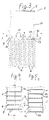
- the coolers 1 consist of flat tubes 2 and corrugated fins 3 arranged between them .
- the corrugated fins 3 were not shown in FIGS. 1 and 2, but can be seen, for example, in FIG. 3.
- the partial view in FIG. 1 shows only one header box 5.
- the other header box 5 is arranged identically at the opposite ends 4 of the flat tubes 2 . All parts are made of aluminum and are coated with solder as required.
- the collecting boxes 5 are of the simplest geometrical shape, so that their production is possible very inexpensively using known methods of forming technology.
- Each collecting box 5 has two connecting edges 7 with which it overlaps the narrow sides 11 of the flat tubes 2 at the ends 4 in the section 12 (FIG. 2).
- the ends 4 of the compartment tubes 2 each have a separating cut 8 .
- the separating cut 8 runs in the direction of the large diameter D of the flat tubes 2, or parallel to the long sides 6. This has the advantage that both narrow sides 11 of the flat tubes 2 are wide enough to make a firm and tight connection with the connecting edges 7 .
- the ends 4 of the flat tubes have two parts 2a and 2b .
- the parts 2a and 2b are bent transversely to the longitudinal direction of the flat tubes 2 , that is to say they have two bends 9 according to FIGS. 1, 2, 3, 8, 10. As the figures show, these bends 9 are not necessarily sharp bends.
- a bend 9 is understood to mean at least one change in direction.
- the specific design of the bends 9 depends on the distance between the flat tubes 2 and the height of the corrugated fins 3 in the fin-tube block.
- the turns 9 cause the longitudinal side 6 of a flat tube 2 with the longitudinal side 6 of the part 2b of the adjacent flat tube 2 are each give a compound surface 10 of the part 2a.
- the ends 4 of the flat tubes 2 are cut open after the flat tubes 2 have been cut to length.
- the cut flat tubes 2 can then be joined together with the corrugated fins 3 to form a fin-tube block.
- the parts 2a and 2b can then be bent as described.
- the collecting boxes are block 5 is mounted in such a way that their joining edges are pushed 7 on both sides over the separated portion 12 of the ends 4 of the flat tubes 2 - to the thus prepared ribs - tube.
- the connecting edges 7 also include the bends 9 , which is particularly evident from FIG. 3.
- the collecting boxes 5 extend with their connecting edges 7 to just below the section 12. It is also possible to make the bends 9 directly after the ends 4 of the flat tubes 2 have been separated and only then to join the finned tube block.
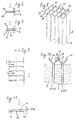
- the partial view of the cooler 1 in FIG. 3 further shows that, in the embodiments described so far, both parts 2a and 2b have been bent and 2 connecting surfaces 10 form due to the abutment of the longitudinal sides 6 of adjacent flat tubes.
- the end faces of the collecting boxes 5 are closed with a cover 20 .
- 4 shows the section A - A through part of the cooler 1.
- the section runs just below the cut section 12 and therefore shows the flat tubes 2, which are not cut there.
- the flat tubes 2 have long sides 6 and narrow sides 11, the narrow sides 11 being already connected to the connecting edge 7 of the header boxes 5 in this area.
- 5 shows a section through the connecting surfaces 10 in FIG. 3. This shows what has already been mentioned above that the longitudinal sides 6 of adjacent flat tubes 2 form the connecting surfaces 10 , namely through part 2a of a flat tube 2 and one Part 2b of the adjacent flat tube 2. Both parts 2a and 2b have bends 9 .
- FIG. 5 shows that there is no constriction of the flow channel 16 , so that there can be no pressure loss caused thereby.
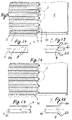
- 7 shows an embodiment in which flat tubes 2 welded with a longitudinal seam 14 have been used.
- the longitudinal seam 14 is located in a longitudinal wall 6 of the flat tube 2, but in relative proximity to a narrow side 11, because there is a higher rigidity in the tube, which facilitates the connection by means of welding.
- the weld seam 14 should be arranged at least outside the separating cut 8.
- 8 to 11 show an embodiment in which flat tubes 2 provided with a longitudinal bead 13 on both longitudinal sides 6 are used.
- the longitudinal beads 13 lie one on top of the other and because they are soldered to one another, two flow channels 16 are formed in the flat tube 2.
- the longitudinal beads 13 could be disruptive in the connecting surfaces 10 , that is to say there could be leaks here. It has therefore been provided in this exemplary embodiment to remove the longitudinal beads 13 in the region of the connecting surfaces 10 by pressing them flat.
- the material required for the longitudinal beads 13 was pressed outwards and leads to an enlargement of the narrow sides 11 within the area of the connecting surfaces 10, which is shown in FIG. 8 but in particular in FIG. 10.
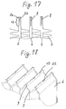
- 12 is a partial side view of the fins 3 - tube 2 - block with bent ends 4 of the flat tubes 2. There the detail W has been drawn in, which is shown in FIGS. 13 and 14 in two different versions. In FIG.
- the separating cut 8 has an approximately circular hole 21 at its beginning or end. Something like this has proven to be advantageous if the bend 9 must be relatively large because the tearing of the narrow sides 11 of the flat tubes 2 can be counteracted.
- the holes 21 can e.g. B. in the manufacture of the separating cuts 8 by means of a laser beam or water jet, by piercing the beam there and then leading to the end 4 of the flat tube 2 . In most cases, however, such end crater-like holes 21 are not required and have not been provided according to FIG. 14. 15 and 16 show a further variant in which only the parts 2b of the ends 4 of the flat tubes 2 have been bent. Parts 2a remain straight. In the same way, 6 connecting surfaces 10 are formed with the adjacent longitudinal sides.
- FIG. 17 shows a section with three flat tubes 2, in which the separating cut 8 has been made, whereby two parts 2a; 2b arise.
- the depth of the separating cut 8 determines the size of the cut section 12 .
- the separating cut 8 lies exactly between the two long sides 6.
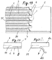
- Fig. 18 shows an additional measure, which consists in that between the adjacent longitudinal sides 6 of two adjacent flat tubes 2, or their parts 2a; 2b, one or more pressure joining points 22 have been arranged.
- Such pressure joining points 22 are known to be attached using suitable forming tools. In the present case, the pressure joining points 22 can take place, for example, together with the attachment of the bends 9 if the bends 9 are to be attached after the ribs 3- pipe 2- block have been joined together.
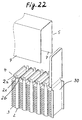
- the heat exchanger in FIGS. 19 to 28 is an air-cooled intercooler for motor vehicles, which consists of flat tubes 2 and corrugated fins 3 arranged between them.
- the flat tubes 2 are welded, extruded or drawn.
- the partial view in FIG. 19 shows only one collecting box 5.
- the other collecting box 5 is arranged identically at the opposite ends 4 of the flat tubes 2 . All parts are made of aluminum and are coated with solder as required.
- the collecting boxes 5 are of the simplest geometrical shape, so that their production is possible very inexpensively using known methods of forming technology.
- Each collecting box 5 has two connecting edges 7, with which it engages over the narrow sides 11 of the flat tubes 2 at the ends 4 in the section which has been separated.
- the ends 4 of the compartment tubes 2 each have a separating cut 8 .
- the separating cut 8 runs in the direction of the large diameter of the flat tubes 2, or parallel to the long sides 6. This has the advantage that both narrow sides 11 of the flat tubes 2 are wide enough to make a firm and tight connection with the connecting edges 7 .
- the ends 4 of the flat tubes have two parts 2a and 2b .
- the wider parts 2a remain undeformed, while the narrower parts 2b have a bend 9 .
- the bends 9 are designed so that the long side 6 of the flat tubes 2 of the narrower parts 2b abuts on the long side 6 of the adjacent flat tube 2 , in each case on the long side 6, which belongs to the non-bent, wider part 2a , which the Fig. 19 clearly shows.
- undeformed side parts 30 were used which at the same time close the front openings of the collecting boxes 5 .
- these undeformed middle parts 2c have a favorable effect on the soldered connection between the connecting edges 7 of the header boxes 5 and the narrow sides 11 of the flat tubes 2 , because the middle parts 2c are also connected to the connecting edge 7 .
- the bends 9 are also carried out here so that the long side 6 of the flat tube 2 or the narrower part 2a abuts the long side 6 of the corresponding part 2b of the adjacent flat tube 2 , so that they can be tightly connected by means of soldering. This is also shown in particular by FIGS. 19, 22 and 23. Shortly below the separating cut 8 in the flat tube ends 4 , the ends 4 of the flat tubes 2 have not yet been separated.
- FIG. 19 further shows that in this exemplary embodiment continuous, deformed side panels 30 were used. Such side parts 30 also have the next embodiment that is shown in FIGS. 26, 27 and 28.
- the narrow sides 11 of the flat tubes 2 are first provided with a cutout, as is shown in FIG. 27.
- the cutout takes up about 50% of the width B of the narrow side 11 of the flat tubes 2 , so that sufficiently wide edges remain on the parts 2a and 2b , which allow a secure connection at the connecting edges 7 .
Abstract
Description
Die Erfindung betrifft einen Wärmetauscher für Kraftfahrzeuge mit einem Rippen -
Rohr - Block, bestehend aus Flachrohren mit dazwischen angeordneten Rippen,
wobei die umgeformten Enden der Flachrohre in gegenüberliegenden Sammel -
oder Umlenkkästen münden und mit den Längsseiten der umgeformten Enden
untereinander verbunden sind, wobei die Enden der Flachrohre mit den Verbindungsrändern
der Sammel - oder Umlenkkästen in Kontakt und mittels Löten verbunden
sind.
Ferner betrifft die Erfindung ein Verfahren zur Herstellung solcher Wärmetauscher,
bei dem der Rippen - Rohr - Block mit den Sammel - oder Umlenkkästen gleichzeitig
verlötet werden.
In jüngerer Zeit häufen sich die Vorschläge über Wärmetauscher bzw. Kühler, die
insgesamt aus Aluminium herstellbar sind, weil die Automobilindustrie sich durch
staatliche Vorschriften gezwungen sieht, die Recyclefähigkeit von PKW' s deutlich
zu verbessern.
An und für sich sind solche Kühler schon seit langem Stand der Technik, wie beispielsweise
die DE - PS 1 551 448 aus 1967 oder das deutsche Gebrauchsmuster
Nr. 1 519 204 aus 1940 zeigen. Davon unterscheidet sich die neuere deutsche
Anmeldung Nr. 195 43 986 A1 nur unwesentlich.
Die genannten Veröffentlichungen beinhalten Wärmetauscher, die häufig als "rohrbodenlose"
Wärmetauscher bezeichnet werden, weil sie im Unterschied zu den
weitverbreiteten Wärmetauschern mit Rohrböden, bei denen die Enden der Flachrohre
in Öffnungen der Rohrböden stecken, deren Ränder mit den Sammelkästen
verbunden sind, aufgeweitete Rohrenden besitzen, die direkt mit den Sammelkästen
und miteinander verbunden sind und somit keine Rohrböden erfordern.
Nachteilig an dem genannten Stand der Technik ist der beträchtliche Umformgrad,
dem die Rohrenden unterzogen werden, weshalb qualitativ hochwertige Werkstoffe
notwendig sind. Die Flachrohre weisen rechteckig umgeformte Enden auf, wobei in
der Regel der große Durchmesser der Rechtecke wesentlich kleiner ist, als der
große Durchmesser der Flachrohre. Diese Einschnürung führt zu strömungstechnischen
Nachteilen. Ferner gibt es Probleme, die Sammelkästen mit den rechteckigen
Enden mittels Löten dicht zu bekommen. Das trifft insbesondere auf die Eckbereiche
der aneinander liegenden Flachrohrenden zu.
Die vor kurzem von der Anmelderin eingereichte deutsche Anmeldung Nr. 100 16
113.8 hat die angeführten Nachteile bereits abgeschwächt oder ganz aufgehoben.
Mit der vorliegenden Patentanmeldung werden alternative Lösungsvorschläge angestrebt,
die die Möglichkeit bieten, geschweißte oder gezogene Flachrohre einzusetzen
und die im übrigen die erwähnten Nachteile ebenfalls beseitigen sollen.The invention relates to a heat exchanger for motor vehicles with a finned tube block consisting of flat tubes with fins arranged therebetween, the shaped ends of the flat tubes opening into opposite collecting or deflection boxes and being connected to one another with the long sides of the shaped ends, the ends being connected the flat tubes are in contact with the connecting edges of the collecting or deflection boxes and are connected by means of soldering.
The invention further relates to a method for producing such heat exchangers, in which the finned tube block is soldered to the header or deflection boxes at the same time.
Recently, there have been increasing proposals for heat exchangers or coolers, which can be made entirely of aluminum, because the automotive industry is forced by state regulations to significantly improve the recyclability of cars.
In and of themselves, such coolers have long been state of the art, as shown, for example, by DE-PS 1 551 448 from 1967 or German utility model No. 1 519 204 from 1940. The more recent German application No. 195 43 986 A1 differs only slightly from this.
The publications mentioned contain heat exchangers, which are often referred to as "tube plate-less" heat exchangers because, in contrast to the widespread heat exchangers with tube plates, in which the ends of the flat tubes are inserted into openings in the tube plates, the edges of which are connected to the header boxes, they have flared tube ends that are directly connected to the header boxes and to each other and therefore do not require tube sheets.
A disadvantage of the prior art mentioned is the considerable degree of deformation to which the pipe ends are subjected, which is why high-quality materials are necessary. The flat tubes have rectangularly shaped ends, the large diameter of the rectangles generally being much smaller than the large diameter of the flat tubes. This constriction leads to fluidic disadvantages. Furthermore, there are problems in sealing the collection boxes with the rectangular ends by means of soldering. This applies in particular to the corner areas of the flat tube ends lying against one another.
The German application No. 100 16 113.8 recently filed by the applicant has already alleviated or eliminated the disadvantages mentioned. The present patent application seeks alternative solutions which offer the possibility of using welded or drawn flat tubes and which, moreover, are also intended to eliminate the disadvantages mentioned.
Bei dem erfindungsgemäßen Wärmetauscher ist vorgesehen, daß die Enden geschweißter
oder extrudierter oder gezogener Flachrohre einen Trennschnitt aufweisen,
der die Enden der Flachrohre in zwei Teile aufteilt, daß mindestens eines
der Teile eines jeden Flachrohres quer zur Längsrichtung eine Abbiegung aufweist,
die zu einer Verbindungsfläche zwischen der Längsseite des Flachrohres und der
Längsseite des Teils des benachbarten Flachrohres führt und daß die Sammel -
oder Umlenkkästen mit ihren Verbindungsrändern bis über die Abbiegung und den
aufgetrennten Abschnitt hinweg reichen und mit den Schmalseiten der Flachrohre
verbunden sind.
Durch diese Ausbildung führt der erfindungsgemäße Wärmetauscher zu folgenden
Vorteilen. Weil am Ende der Flachrohre lediglich relativ geringe Abbiegungen vorhanden
sind, muß kein hochwertiger Werkstoff eingesetzt werden. Die Materialbelastung
ist äußerst gering. Es gibt auch keine Einschnürung an den Enden der
Flachrohre, so daß mit wesentlich geringerem Druckverlust zu rechnen ist, als
beim Stand der Technik. Der Strömungsquerschnitt an den Enden wurde sogar
erweitert, obwohl keine wesentliche Materialdehnung vorhanden ist. Es können
deutlich geringere Wanddicken der Flachrohre zum Einsatz kommen, weil eine
sehr geringe Umformung im Endbereich der Flachrohre vorhanden ist. Auf das Expandieren
der Rohrenden wurde komplett verzichtet.
Gemäß Anspruch 2 ist vorgesehen, daß die Flachrohre geschweißt sind eine oder
mehrere Längssicken aufweisen, die mehrere Strömungskanäle im Flachrohr ausbilden
wobei die Längssicken innerhalb des aufgetrennten Abschnitts umformtechnisch
beseitigt sind.
Geschweißte Flachrohre sind kostengünstiger als gezogene Flachrohre. Das Material
der Längssicken innerhalb des aufgetrennten Abschnittes wird nach außen, in
die Längsränder gedrückt, wodurch die Verbindungsflächen, die sich an den Enden
der benachbarten Flachrohre einstellen, glatt sind und wenig Probleme bezüglich
einer dichten löttechnischen Verbindung bereiten. Dieser Anspruch ist lediglich
fakultativ vorgesehen.
Gemäß Anspruch 4 ist bei geschweißten Flachrohren die Längsnaht außerhalb
des Trennschnittes, vorzugsweise auf einer Längsseite des Flachrohres, in der
Nähe einer Schmalseite des Flachrohres angeordnet. Das vereinfacht die Anbringung
des Trennschnittes.
Gemäß Anspruch 5 sind die Flachrohre gezogene oder extrudierte Rohre und haben
eine oder mehrere Längswände zur Unterteilung in mehrere Strömungskanäle.
Das ist besonders bei Kühlflüssigkeitskühlern vorteilhaft.
Nach Anspruch 6 kann jedoch auf Längssicken oder Längswände verzichtet werden.
Für diesen Fall ist ein Inneneinsatz vorgesehen. Das ist besonders für Ladeluftkühler
vorteilhaft.
Anspruch 7 sieht vor, daß beide Enden bzw. beide Teile eines jeden Flachrohres
jeweils zwei quer zur Längsrichtung des Flachrohres angeordnete Abbiegungen
aufweisen, wobei die eine Abbiegung etwa dort angeordnet ist, wo die Verbindungsfläche
der Längsseite des einen Flachrohres mit der Längsseite des benachbarten
Flachrohres beginnt und die andere Abbiegung etwa dort vorgesehen
ist, wo der aufgetrennte Abschnitt der Flachrohre beginnt bzw. endet. Der Trennschnitt
ist vorzugsweise parallel zu den Längsseiten eines jeden Flachrohres angeordnet,
so daß beide Stirnseiten des Flachrohres aufgetrennt sind. Dadurch ist
eine vorteilhafte Ausführung der Erfindung gekennzeichnet worden. Im Gegensatz
zum Anspruch 7 umfaßt Anspruch 1 auch Ausführungen mit nur einer Abbiegung,
nämlich die am Ende des aufgetrennten Abschnittes, wo das Flachrohr beginnt.
Dort wo die Verbindungsfläche beginnt kann auch ein allmählicher Übergang in die
Verbindungsfläche vorhanden sein.
Anspruch 8 sieht alternativ dazu vor, daß nur eines der erwähnten Teile eine Abbiegung
aufweist und das andere Teil glatt bleibt.
Die Längsseiten der Flachrohre sind auf der Seite, auf der sie mit der Längsseite
des benachbarten Flachrohres eine Verbindungsfläche bilden im wesentlichen
glatt.
Es ist vorteilhaft, wenn zwischen den Längsseiten bzw. in der Verbindungsfläche
ein oder mehrere Druckfügepunkte angeordnet werden.
Das erfindungsgemäße Verfahren sieht vor, daß die Enden der Flachrohre aufgetrennt
und mindestens eines der nach dem Auftrennen entstandenen zwei Teile
eines jeden Flachrohres quer zur Längsrichtung der Flachrohre abgebogen wird,
um mit der Längsseite des benachbarten Flachrohres eine Verbindungsfläche zu
bilden, daß die Sammel - oder Umlenkkästen mit ihren Verbindungsrändern über
den Rippen - Flachrohr - Block geschoben und die Verbindungsränder mit den
Schmalseiten der aufgetrennten Teile der Flachrohre verbunden werden.
Das Auftrennen kann mit einem Laserstrahl oder einem Flüssigkeitsstrahl oder
mittels üblicher Trennmittel erfolgen und geschieht vorzugsweise parallel zu den
Längsseiten der Flachrohre, genau in der Mitte zwischen beiden Längsseiten.
Vorzugsweise ist vorgesehen, daß beide Teile der Flachrohre einfach oder zweifach
quer zur Längsrichtung der Flachrohre abgebogen werden.
Bei dem Wärmetauscher der angegebenen Art ist gemäß Anspruch 11 vorgesehen,
daß der mindestens eine Trennschnitt außerhalb der Mittellinie an mindestens
einer der zwei Schmalseiten angeordnet ist. Vorzugsweise soll der Trennschnitt
parallel zu beiden Längsseiten des Flachrohres, also an beiden Schmalseiten außerhalb
ihrer Mittellinie, angeordnet sein. Die Anbringung mindestens eines außermittigen
Trennschnittes ist für Wärmetauscher mit Flachrohren mit etwas breiteren
Schmalseiten sehr vorteilhaft, weil der schmalere, abgetrennte Teil der Enden
der Flachrohre leichter umgeformt, bzw. abgebogen werden kann.
Gemäß Anspruch 12 wurde daran gedacht, das schmalere Teil der Enden der
Flachrohre umzuformen und das breitere Teil unverformt zu belassen, so daß die
zum schmaleren Teil gehörende Längsseite des einen Flachrohres an der zum
breiteren, unverformten Teil gehörenden Längsseite des benachbarten Flachrohres
anliegt.
Anspruch 13 sieht demgegenüber vor, zwei, vorzugsweise parallele, außermittige
Trennschnitte in den Schmalseiten der Enden der Flachrohre anzuordnen, wobei
das durch die Trennschnitte entstehende Mittelteil unverformt bleibt und beide seitlichen
Teile abgebogen sind, so daß ihre Längsseiten an den Längsseiten benachbarter
Flachrohrenden anliegen.In the heat exchanger according to the invention it is provided that the ends of welded or extruded or drawn flat tubes have a separating cut which divides the ends of the flat tubes into two parts, that at least one of the parts of each flat tube has a bend transversely to the longitudinal direction which leads to a connecting surface between The long side of the flat tube and the long side of the part of the adjacent flat tube leads and that the collecting or deflection boxes with their connecting edges extend over the bend and the cut section and are connected to the narrow sides of the flat tubes.
As a result of this design, the heat exchanger according to the invention has the following advantages. Because there are only relatively small bends at the end of the flat tubes, no high-quality material has to be used. The material load is extremely low. There is also no constriction at the ends of the flat tubes, so that a much lower pressure loss can be expected than in the prior art. The flow cross-section at the ends was even expanded, although there is no significant material expansion. Significantly smaller wall thicknesses of the flat tubes can be used because there is very little deformation in the end area of the flat tubes. There was no need to expand the pipe ends.
According to
Welded flat tubes are cheaper than drawn flat tubes. The material of the longitudinal beads within the cut-off section is pressed outwards into the longitudinal edges, as a result of which the connecting surfaces which form at the ends of the adjacent flat tubes are smooth and pose little problem with regard to a tight soldered connection. This claim is only optional.
In the case of welded flat tubes, the longitudinal seam is arranged outside the separating cut, preferably on a long side of the flat tube, in the vicinity of a narrow side of the flat tube. This simplifies the application of the separating cut.
According to
According to
Where the connection surface begins, there may also be a gradual transition into the connection surface.
The long sides of the flat tubes are essentially smooth on the side on which they form a connecting surface with the long side of the adjacent flat tube.
It is advantageous if one or more pressure joining points are arranged between the long sides or in the connecting surface.
The method according to the invention provides that the ends of the flat tubes are separated and at least one of the two parts of each flat tube formed after the separation is bent transversely to the longitudinal direction of the flat tubes in order to form a connecting surface with the longitudinal side of the adjacent flat tube that the collecting or Deflection boxes with their connecting edges are pushed over the ribbed flat tube block and the connecting edges are connected to the narrow sides of the separated parts of the flat tubes.
The separation can be carried out with a laser beam or a liquid jet or by means of conventional separating means and is preferably carried out parallel to the long sides of the flat tubes, exactly in the middle between the two long sides. It is preferably provided that both parts of the flat tubes are bent once or twice transversely to the longitudinal direction of the flat tubes.
In the heat exchanger of the type specified, it is provided according to
According to
Als weitere alternative Lösung ist gemäß Anspruch 14 vorgesehen, daß der Trennschnitt
mittels eines symmetrischen oder asymmetrischen Ausschnitts der Schmalseiten
gebildet ist. Das hat den Vorteil, daß beidseitig des Ausschnitts relativ
schmale Teile vorhanden sind, die sich ebenfalls vorteilhaft abbiegen lassen.As a further alternative solution is provided according to
Der Ausschnitt wird vorzugsweise mit einem Werkzeug ausgeführt, mit dem der Ausschnitt in beiden gegenüberliegenden Schmalseiten in einem Arbeitsgang erfolgen kann. Das nachfolgende Abbiegen der schmalen Teile kann gleichzeitig mit der Anbringung des Ausschnitts, aber auch später, nach dem Zusammenfügen des Rippen - Flachrohr - Blocks, durchgeführt werden.The cutout is preferably carried out with a tool with which the Cut out in both opposite narrow sides in one operation can. The subsequent turning of the narrow parts can be done simultaneously the attachment of the cutout, but also later, after the assembly of the Ribs - flat tube blocks.
Weitere Merkmale sind in den Patentansprüchen enthalten. Außerdem gehen Merkmale und Wirkungen aus der nachfolgenden Beschreibung von Ausführungsbeispielen hervor. Es wird Bezug auf die beiliegenden Zeichnungen genommen. Die einzelnen Figuren zeigen Folgendes:
- Fig.1
- Perspektivansicht auf einen Teil des erfindungsgemäßen Kühlers mit Sammelkasten;
- Fig. 2
- Perspektivansicht aus einem anderen Blickwinkel ohne Sammelkasten;
- Fig. 3
- Teil einer Seitenansicht;
- Fig. 4
- Schnitt A - A aus Fig. 3;
- Fig. 5
- Schnitt B - B aus Fig. 3;
- Fig. 6
- Einzelheit "V" von Fig. 4;
- Fig. 7
- Einzelheit "U" aus Fig. 4;
- Fig. 8
- Perspektivansicht einer zweiten Ausführung;
- Fig. 9
- Schnitt A-A in Fig. 8;
- Fig. 10
- vergrößerter Ausschnitt aus Fig. 8;
- Fig. 11
- Einzelheit "Z" in Fig. 9 ;
- Fig. 12
bis 14 - Einzelheiten der Auftrennung der Enden der Flachrohre;
- Fig. 15
- Schnitt durch eine dritte Ausführungsform;
- Fig. 16
- Seitenansicht von Fig. 15;
- Fig. 17
- Flachrohr mit aufgetrenntem Abschnitt;
- Fig. 18
- Variante mit Verbindung der Längsseiten der Flachrohre;
- Fig. 19
- Schnitt durch eine vierte Ausführungsform;
- Fig. 20 u. 21
- Rohrende der vierten Ausführungsform;
- Fig. 22
- Perspektivansicht der fünften Ausführungsform;
- Fig. 23
- Seitenansicht der fünften Ausführungsform;
- Fig. 24 u. 25
- Rohrende der fünften Ausführungsform;
- Fig. 26
- Längsschnitt der sechsten Ausführungsform;
- Fig. 27 u. 28
- Rohrende der sechsten Ausführungsform;
- Fig. 1
- Perspective view of a part of the cooler according to the invention with collecting box;
- Fig. 2
- Perspective view from a different point of view without collecting box;
- Fig. 3
- Part of a side view;
- Fig. 4
- Section A - A of Fig. 3;
- Fig. 5
- Section BB from FIG. 3;
- Fig. 6
- Detail "V" of Fig. 4;
- Fig. 7
- Detail "U" from Fig. 4;
- Fig. 8
- Perspective view of a second embodiment;
- Fig. 9
- Section AA in Fig. 8;
- Fig. 10
- enlarged section of Fig. 8;
- Fig. 11
- Detail "Z" in Fig. 9;
- 12 to 14
- Details of the separation of the ends of the flat tubes;
- Fig. 15
- Section through a third embodiment;
- Fig. 16
- Side view of Fig. 15;
- Fig. 17
- Flat tube with cut section;
- Fig. 18
- Variant with connection of the long sides of the flat tubes;
- Fig. 19
- Section through a fourth embodiment;
- Fig. 20 u. 21
- Pipe end of the fourth embodiment;
- Fig. 22
- Perspective view of the fifth embodiment;
- Fig. 23
- Side view of the fifth embodiment;
- 24 u. 25th
- Pipe end of the fifth embodiment;
- Fig. 26
- Longitudinal section of the sixth embodiment;
- Fig. 27 u. 28
- Pipe end of the sixth embodiment;
Die Kühler 1 bestehen aus Flachrohren 2 und dazwischen angeordneten Wellrippen
3. Die Wellrippen 3 wurden in den Figuren 1 und 2 nicht gezeichnet, sind aber
beispielsweise in Fig. 3 zu erkennen. Die Teilansicht in der Fig. 1 zeigt lediglich
einen Sammelkasten 5. Es versteht sich, daß der andere Sammelkasten 5 an den
gegenüberliegenden Enden 4 der Flachrohre 2 identisch angeordnet ist. Sämtliche
Teile bestehen aus Aluminium und sind nach Bedarf mit Lot beschichtet. Die
Sammelkästen 5 sind von einfachster geometrischer Form, so daß ihre Herstellung
sehr kostengünstig mit bekannten Verfahren der Umformtechnik möglich ist. Jeder
Sammelkasten 5 hat zwei Verbindungsränder 7 mit denen er die Schmalseiten 11
der Flachrohre 2 an den Enden 4 im aufgetrennten Abschnitt 12 (Fig. 2) übergreift.
Die Enden 4 der Fachrohre 2 weisen jeweils einen Trennschnitt 8 auf. Der Trennschnitt
8 verläuft in der Richtung des großen Durchmessers D der Flachrohre 2,
bzw. parallel zu den Längsseiten 6. Das hat den Vorteil, daß beide Schmalseiten
11 der Flachrohre 2 breit genug sind, um mit den Verbindungsrändern 7 eine feste
und dicht Verbindung einzugehen. Nachdem der Trennschnitt 8 an den Enden 4
der Flachrohre 2 angebracht wurde, weisen die Enden 4 der Flachrohre zwei Teile
2a und 2b auf. Die Teile 2a und 2b werden quer zur Längsrichtung der Flachrohre
2 abgebogen, sie weisen also gemäß den Fig. 1, 2, 3, 8, 10 u. a. zwei Abbiegungen
9 auf. Wie die Figuren zeigen, sind diese Abbiegungen 9 nicht unbedingt
scharfe Abkantungen. Unter einer Abbiegung 9 ist zumindest eine Richtungsänderung
zu verstehen. Im Einzelfall hängt die konkrete Ausbildung der Abbiegungen 9
von dem Abstand der Flachrohre 2 bzw. der Höhe der Wellrippen 3 im Rippen -
Rohr - Block ab. Die Abbiegungen 9 führen dazu, daß die Längsseite 6 des Teiles
2a eines Flachrohres 2 mit der Längsseite 6 des Teiles 2b des benachbarten
Flachrohres 2 jeweils eine Verbindungsfläche 10 ergeben. Das Auftrennen der Enden
4 der Flachrohre 2 erfolgt nach dem Ablängen der Flachrohre 2. Dann können
die abgelängten Flachrohre 2 mit den Wellrippen 3 zum Rippen - Rohr - Block
zusammengefügt werden. Anschließend können dann die Teile 2a und 2b, wie beschrieben,
abgebogen werden. An den so vorbereiteten Rippen - Rohr - Block
werden die Sammelkästen 5 angebracht und zwar derart, daß ihre Verbindungsränder
7 auf beiden Seiten über den aufgetrennten Abschnitt 12 der Enden 4 der
Flachrohre 2 geschoben werden. Dabei schließen die Verbindungsränder 7 auch
die Abbiegungen 9 ein, was insbesondere aus der Fig. 3 hervorgeht. Die Sammelkästen
5 reichen mit ihren Verbindungsrändern 7 bis kurz unterhalb des aufgetrennten
Abschnitts 12. Es ist aber auch möglich, die Abbiegungen 9 direkt im Anschluß
an das Auftrennen der Enden 4 der Flachrohre 2 anzubringen und erst danach
den Rippen - Rohr - Block zusammenzufügen.
Die Teilansicht des Kühlers 1 in der Fig. 3 zeigt weiter, daß in den bisher geschilderten
Ausführungen beide Teile 2a und 2b abgebogen wurden und durch das Anliegen
der Längsseiten 6 benachbarter Flachrohre 2 Verbindungsflächen 10 bilden.
Die Stirnseiten der Sammelkästen 5 sind mit einem Deckel 20 verschlossen. Die
Fig. 4 stellt den Schnitt A - A durch einen Teil des Kühlers 1 dar. Der Schnitt verläuft
kurz unterhalb des aufgetrennten Abschnitts 12 und zeigt deshalb die Flachrohre
2, die dort nicht aufgetrennt sind. Die Flachrohre 2 haben Längsseiten 6 und
Schmalseiten 11, wobei die Schmalseiten 11 mit dem Verbindungsrand 7 der
Sammelkästen 5 in diesem Bereich schon verbunden sind. Die Fig. 5 stellt einen
Schnitt durch die Verbindungsflächen 10 in Fig. 3 dar. Daraus geht hervor, was
oben bereits angesprochen wurde, daß die Längsseiten 6 benachbarter Flachrohre
2 die Verbindungsflächen 10 bilden und zwar durch ein Teil 2a des einen Flachrohres
2 und ein Teil 2b des benachbarten Flachrohres 2. Beide Teile 2a und 2b weisen
Abbiegungen 9 auf. Die Schmalseiten 11 der Flachrohre 2, bzw. der beiden
Teile 2a und 2b, sind auch hier dicht und fest mit den Verbindungsrändern 7 verbunden.
(siehe auch Fig. 6) Insbesondere geht aus Fig. 5 hervor, daß keinerlei
Einschnürung des Strömungskanals 16 vorhanden ist, so daß es keinen dadurch
verursachten Druckverlust geben kann.
Die Fig. 7 zeigt ein Ausführungsbeispiel, bei dem mit einer Längsnaht 14 geschweißte
Flachrohre 2 verwendet worden sind. Die Längsnaht 14 befindet sich in
einer Längswand 6 des Flachrohres 2, allerdings in relativer Nähe zu einer
Schmalseite 11, weil dort eine höhere Steifigkeit im Rohr gegeben ist, die die Verbindung
mittels Schweißen erleichtert. Die Schweißnaht 14 sollte zumindest außerhalb
des Trennschnittes 8 angeordnet sein.
In den Fig. 8 bis 11 ist ein Ausführungsbeispiel abgebildet, bei dem mit je einer
Längssicke 13 auf beiden Längsseiten 6 versehene Flachrohre 2 verwendet werden.
Die Längssicken 13 liegen aufeinander und weil sie miteinander verlötet sind,
entstehen zwei Strömungskanäle 16 in dem Flachrohr 2. Die Längssicken 13
könnten in den Verbindungsflächen 10 störend sein, das heißt, es könnten hier
Undichtigkeiten entstehen. Deshalb hat man in diesem Ausführungsbeispiel vorgesehen,
im Bereich der Verbindungsflächen 10 die Längssicken 13 zu entfernen,
indem dieselben glattgedrückt wurden. Das für die Längssicken 13 erforderliche
Material wurde nach außen gepreßt und führt zu einer Vergrößerung der Schmalseiten
11 innerhalb des Bereiches der Verbindungsflächen 10, was die Fig. 8 aber
insbesondere die Fig. 10 zeigt.
Die Fig. 12 ist eine Teil - Seitenansicht auf den Rippen 3 - Rohr 2 - Block mit abgebogenen
Enden 4 der Flachrohre 2. Dort ist die Einzelheit W eingezeichnet worden,
die in den Fig. 13 und 14 in zwei verschiedenen Ausführungen gezeigt ist. In
Fig. 13 weist der Trennschnitt 8 an seinem Anfang bzw. Ende ein etwa kreisrundes
Loch 21 auf. So etwas hat sich als vorteilhaft erwiesen, wenn die Abbiegung 9 relativ
groß sein muß, weil dem Einreißen der Schmalseiten 11 der Flachrohre 2 entgegengewirkt
werden kann. Die Löcher 21 können z. B. bei der Herstellung der
Trennschnitte 8 mittels Laserstrahl oder Wasserstrahl hergestellt werden, indem
der Strahl dort durchsticht und dann zum Ende 4 des Flachrohres 2 geführt wird. In
den meisten Fällen sind solche endkraterartigen Löcher 21 jedoch nicht erforderlich
und gemäß Fig. 14 nicht vorgesehen worden.
Die Fig. 15 und 16 zeigen eine weitereVariante, bei der lediglich die Teile 2b der
Enden 4 der Flachrohre 2 abgebogen wurden. Die Teile 2a bleiben gerade. In gleicher
Weise werden mit den anliegenden Längsseiten 6 Verbindungsflächen 10
ausgebildet.
Die Fig. 17 zeigt einen Ausschnitt mit drei Flachrohren 2, bei denen der Trennschnitt
8 angebracht wurde, wodurch zwei Teile 2a; 2b entstehen. Die Tiefe des
Trennschnitts 8 legt die Größe des aufgetrennten Abschnitts 12 fest. Der Trennschnitt
8 liegt genau zwischen den beiden Längsseiten 6.
Die Fig. 18 zeigt eine Zusatzmaßnahme, die darin besteht, daß zwischen den anliegenden
Längsseiten 6 zweier benachbarter Flachrohre 2, bzw. deren Teile 2a;
2b, ein oder mehrere Druckfügepunkte 22 angeordnet wurden. Solche Druckfügepunkte
22 werden bekanntermaßen mit geeigneten Umformwerkzeugen angebracht.
Im vorliegenden Fall können die Druckfügepunkte 22 beispielsweise gemeinsam
mit dem Anbringen der Abbiegungen 9 erfolgen, falls die Abbiegungen 9
nach dem Zusammenfügen des Rippen 3 - Rohr 2 - Blocks angebracht werden
sollen. Werden die Abbiegungen 9 bereits nach dem Ablängen der Flachrohre, d.
h., vor dem Zusammenfügen des Rippen 3 - Rohr 2 - Blocks angebracht, ist für
die Herstellung der Druckfügepunkte 22 ein zusätzlicher Arbeitsschritt am zusammengefügten
Rippen 3 - Rohr 2 - Block erforderlich. Die Druckfügepunkte 22 bewirken,
daß der Rippen 3 - Rohr 2 - Block vor dem Löten fest zusammengehalten
wird, so daß Hilfsvorrichtungen entfallen oder deren Aufwand zumindest reduziert
werden kann.
Der Wärmetauscher in den Fig. 19 bis 28 ist ein luftgekühlter Ladeluftkühler für
Kraftfahrzeuge, der aus Flachrohren 2 und dazwischen angeordneten Wellrippen 3
besteht. Die Flachrohre 2 sind geschweißter, extrudierter oder gezogener Ausführung.
Die Teilansicht in der Fig. 19 zeigt lediglich einen Sammelkasten 5. Es versteht
sich, daß der andere Sammelkasten 5 an den gegenüberliegenden Enden 4
der Flachrohre 2 identisch angeordnet ist. Sämtliche Teile bestehen aus Aluminium
und sind nach Bedarf mit Lot beschichtet. Die Sammelkästen 5 sind von einfachster
geometrischer Form, so daß ihre Herstellung sehr kostengünstig mit bekannten
Verfahren der Umformtechnik möglich ist. Jeder Sammelkasten 5 hat zwei
Verbindungsränder 7, mit denen er die Schmalseiten 11 der Flachrohre 2 an den
Enden 4 im aufgetrennten Abschnitt übergreift. Die Enden 4 der Fachrohre 2 weisen
jeweils einen Trennschnitt 8 auf. Der Trennschnitt 8 verläuft in der Richtung
des großen Durchmessers der Flachrohre 2, bzw. parallel zu den Längsseiten 6.
Das hat den Vorteil, daß beide Schmalseiten 11 der Flachrohre 2 breit genug sind,
um mit den Verbindungsrändern 7 eine feste und dichte Verbindung einzugehen.
Nach dem der Trennschnitt 8 an den Enden 4 der Flachrohre 2 - und zwar außerhalb
der Mitte 31 ihrer Schmalseiten 11 - angebracht wurde, weisen die Enden 4
der Flachrohre zwei Teile 2a und 2b auf. Die breiteren Teile 2a bleiben unverformt,
während die schmaleren Teile 2b eine Abbiegung 9 aufweisen. Die Abbiegungen 9
sind so ausgeführt, daß die Längsseite 6 der Flachrohre 2 der schmaleren Teile 2b
an der Längsseite 6 des benachbarten Flachrohres 2 anliegt, und zwar jeweils an
der Längsseite 6, die zum nicht abgebogenen, breiteren Teil 2a gehört, was die
Fig. 19 deutlich zeigt.
Im Ausführungsbeispiel nach Fig. 19 wurden unverformte Seitenteile 30 verwendet,
die gleichzeitig die stirnseitigen Öffnungen der Sammelkästen 5 verschließen.
Die nachfolgend zu beschreibenden Fig. 23 bis 25 betreffen ein Ausführungsbeispiel,
bei dem die Schmalseiten 11 der Flachrohre 2 deutlich breiter sind, als diejenigen
im zuvor beschriebenen Ausführungsbeispiel. Deshalb wurde hier eine Variante
gewählt, bei der die Enden 4 der Flachrohre 2 je zwei Trennschnitte 8 an ihren
Schmalseiten 11 aufweisen. Dadurch entsteht an allen Enden 4 ein Mittelteil 2c
und zwei seitliche Teile 2a, 2b. Wie die Fig. 24 und 25 im Detail zeigen, sind die
seitlichen Teile 2a und 2b in diesem Fall von gleicher Größe und Gestalt und sie
weisen beide die Abbiegungen 9 auf. Das Mittelteil 2c bleibt unverformt. Insbesondere
ist zu erkennen, daß diese unverformten Mittelteile 2c sich günstig auf die
Lötverbindung zwischen den Verbindungsrändern 7 der Sammelkästen 5 und den
Schmalseiten 11 der Flachrohre 2 auswirken, denn auch die Mittelteile 2c sind mit
dem Verbindungsrand 7 verbunden. Die Abbiegungen 9 sind auch hier so ausgeführt,
daß die Längsseite 6 des Flachrohrs 2 bzw. des schmaleren Teils 2a an der
Längsseite 6 des entsprechenden Teils 2b des benachbarten Flachrohrs 2 anliegt,
so daß sie mittels Löten dicht zu verbinden sind. Das zeigen insbesondere ebenfalls
die Figuren 19, 22 und 23.
Kurz unterhalb des Trennschnittes 8 in den Flachrohrenden 4 sind die Enden 4 der
Flachrohre 2 noch nicht aufgetrennt. Auch dort sind die Schmalseiten 11 der Flachrohre
2 bereits mit den Verbindungsrändern 7 der Sammelkästen 5 verbunden.
(Fig. 19, 23) In den Flachrohren 2 befindet sich jeweils ein Inneneinsatz, der für
Turbulenz in der Ladeluft und für effizienten Wärmeaustausch sorgt. Auf den Inneneinsatz
kommt es hier jedoch nicht besonders an, denn die erwähnte Wirkung
kann bekanntlich auch anders erzielt werden, beispielsweise durch Längssicken
und / oder Noppen in den Längsseiten 6 der Flachrohre 2. Die Fig. 19 zeigt weiter,
daß in diesem Ausführungsbeispiel durchgehende, verformte Seitenteile 30 eingesetzt
wurden.
Solche Seitenteile 30 weist auch das nächste Ausführungsbeispiel auf, daß in den
Fig. 26, 27 und 28 gezeigt ist. Hierbei werden die Schmalseiten 11 der Flachrohre
2 zunächst mit einem Ausschnitt versehen, wie das in der Fig. 27 gezeigt ist. Der
Ausschnitt nimmt etwa 50% der Breite B der Schmalseite 11 der Flachrohre 2 ein,
so daß ausreichend breite Ränder an den Teilen 2a und 2b verbleiben, die eine
sichere Verbindung an den Verbindungsrändern 7 gestatten.The
The partial view of the
7 shows an embodiment in which
8 to 11 show an embodiment in which
12 is a partial side view of the fins 3 - tube 2 - block with
15 and 16 show a further variant in which only the parts 2b of the
17 shows a section with three
Fig. 18 shows an additional measure, which consists in that between the adjacent
The heat exchanger in FIGS. 19 to 28 is an air-cooled intercooler for motor vehicles, which consists of
In the exemplary embodiment according to FIG. 19,
23 to 25 to be described below relate to an exemplary embodiment in which the
Shortly below the separating cut 8 in the flat tube ends 4 , the
Claims (21)
dadurch gekennzeichnet, daß
die Enden (4) geschweißter oder extrudierter oder gezogener Flachrohre (2) einen Trennschnitt (8) aufweisen, der die Enden (4) der Flachrohre (2) in zwei Teile (2a; 2b) aufteilt, daß mindestens eines der Teile (2a, 2b) eines jeden Flachrohres (2) quer zur Längsrichtung eine Abbiegung (9) aufweist, die zu einer Verbindungsfläche (10) zwischen der Längsseite (6) des Flachrohres (2) und der Längsseite (6) des Teils (2a; 2b) des benachbarten Flachrohres (2) führt und daß die Sammel - oder Umlenkkästen (5) mit ihren Verbindungsrändern (7) bis über die Abbiegung (9) und den aufgetrennten Abschnitt (12) hinweg reichen und mit den Schmalseiten (11) der Flachrohre (2) verbunden sind.Radiator (1) for motor vehicles with a ribs (3) - flat tube (2) - block, consisting of flat tubes (2) with ribs (3) arranged between them, the shaped ends (4) of the flat tubes (2) being arranged in opposite collectors - or deflection boxes (5) open and are connected to one another with the longitudinal sides (6) of the formed ends (4), the ends (4) of the flat tubes (2) being in contact with the connecting edges (7) of the collecting or deflection boxes (5) and are connected by soldering,
characterized in that
the ends (4) of welded or extruded or drawn flat tubes (2) have a separating cut (8) which divides the ends (4) of the flat tubes (2) into two parts (2a; 2b) such that at least one of the parts (2a, 2b) of each flat tube (2) transversely to the longitudinal direction has a bend (9) leading to a connecting surface (10) between the long side (6) of the flat tube (2) and the long side (6) of the part (2a; 2b) leads adjacent flat tube (2) and that the collecting or deflection boxes (5) with their connecting edges (7) extend beyond the bend (9) and the separated section (12) and with the narrow sides (11) of the flat tubes (2) are connected.
dadurch gekennzeichnet, daß
die Enden (4) der Flachrohre (2 aufgetrennt und mindestens eines der nach dem Auftrennen entstandenen zwei Teile (2a; 2b) eines jeden Endes (4) der Flachrohre (2) quer zur Längsrichtung der Flachrohre (2) abgebogen wird, um mit der Längsseite (6) des benachbarten Flachrohres (2) eine Verbindungsfläche (10) zu bilden, daß die Sammel - oder Umlenkkästen (5) mit ihren Verbindungsrändern (7) über den Rippen - Flachrohr - Block geschoben und die Verbindungsränder (7) mit den Schmalseiten (11) der aufgetrennten Enden (4) der Flachrohre (2) verbunden werden.Method for producing the cooler or heat exchanger according to Claim 1 or one of Claims 2 to 15, in which the fins (3) - flat tube (2) - block are soldered to the collecting or deflecting boxes (5) at the same time,
characterized in that
the ends (4) of the flat tubes (2 are separated and at least one of the two parts (2a; 2b) of each end (4) of the flat tubes (2) formed after the separation is bent transversely to the longitudinal direction of the flat tubes (2) in order to be able to bend To form a connecting surface (10) on the long side (6) of the adjacent flat tube (2), that the collecting or deflection boxes (5) with their connecting edges (7) are pushed over the ribbed flat tube block and the connecting edges (7) with the narrow sides (11) of the separated ends (4) of the flat tubes (2) are connected.
Applications Claiming Priority (4)
| Application Number | Priority Date | Filing Date | Title |
|---|---|---|---|
| DE2000119268 DE10019268A1 (en) | 2000-03-31 | 2000-04-19 | Vehicle refrigerator; has block with ribs arranged between flat pipes, where flat pipes open into opposite collecting guiding tanks and have bent separated sections connected to adjacent flat pipes |
| DE10019268 | 2000-04-19 | ||
| DE2000160006 DE10060006A1 (en) | 2000-12-02 | 2000-12-02 | Vehicle refrigerator; has block with ribs arranged between flat pipes, where flat pipes open into opposite collecting guiding tanks and have bent separated sections connected to adjacent flat pipes |
| DE10060006 | 2000-12-02 |
Publications (2)
| Publication Number | Publication Date |
|---|---|
| EP1148312A1 true EP1148312A1 (en) | 2001-10-24 |
| EP1148312B1 EP1148312B1 (en) | 2004-07-28 |
Family
ID=26005374
Family Applications (1)
| Application Number | Title | Priority Date | Filing Date |
|---|---|---|---|
| EP01107034A Expired - Lifetime EP1148312B1 (en) | 2000-04-19 | 2001-03-21 | Radiator for vehicles |
Country Status (5)
| Country | Link |
|---|---|
| US (1) | US20010037878A1 (en) |
| EP (1) | EP1148312B1 (en) |
| AT (1) | ATE272201T1 (en) |
| DE (1) | DE50102959D1 (en) |
| ES (1) | ES2225332T3 (en) |
Cited By (3)
| Publication number | Priority date | Publication date | Assignee | Title |
|---|---|---|---|---|
| US5725563A (en) * | 1993-04-21 | 1998-03-10 | Klotz; Antoine | Electronic device and method for adrenergically stimulating the sympathetic system with respect to the venous media |
| DE102004053892A1 (en) * | 2004-11-09 | 2006-05-11 | Modine Manufacturing Co., Racine | Heat transformer, has flat tubes with flow separation that is performed by longitudinal crimp supported at non deformed side of tubes, where crimp in ends of tubes changes by deformation in side of tubes |
| US8002022B2 (en) | 2005-09-16 | 2011-08-23 | Behr Gmbh & Co. Kg | Heat exchanger, in particular exhaust gas heat exchanger for motor vehicles |
Families Citing this family (7)
| Publication number | Priority date | Publication date | Assignee | Title |
|---|---|---|---|---|
| DE10147192A1 (en) | 2001-09-25 | 2003-04-17 | Modine Mfg Co | Heat exchanger with a finned flat tube block and manufacturing process |
| US7195060B2 (en) * | 2005-04-01 | 2007-03-27 | Dana Canada Corporation | Stacked-tube heat exchanger |
| US8646516B2 (en) * | 2006-08-17 | 2014-02-11 | Pana Canada Corporation | Alternating plate headerless heat exchangers |
| DE102011077838A1 (en) * | 2011-06-20 | 2012-12-20 | Behr Gmbh & Co. Kg | Heat exchanger and method for producing a heat exchanger |
| DE102014206612A1 (en) * | 2014-04-04 | 2015-10-29 | Mahle International Gmbh | heat exchangers |
| JP2017009191A (en) * | 2015-06-22 | 2017-01-12 | 株式会社ティラド | Temporary assembly means of header plate and core of heat exchanger |
| JP7244439B2 (en) * | 2017-12-27 | 2023-03-22 | 株式会社ティラド | Header plateless heat exchanger |
Citations (6)
| Publication number | Priority date | Publication date | Assignee | Title |
|---|---|---|---|---|
| CH378353A (en) * | 1960-09-01 | 1964-06-15 | Urech Karl | Heat exchanger with plate-shaped exchange elements |
| DE1551448A1 (en) | 1967-02-17 | 1970-04-16 | Daimler Benz Ag | Heat exchangers, especially for portable gas turbines |
| DE1951138A1 (en) * | 1968-10-11 | 1970-04-23 | Vmw Ranshofen Berndorf Ag | Light metal radiator for transformers |
| GB1304284A (en) * | 1969-02-21 | 1973-01-24 | ||
| US5392849A (en) * | 1990-09-28 | 1995-02-28 | Matsushita Refrigeration Company | Layer-built heat exchanger |
| EP0775884A2 (en) * | 1995-11-25 | 1997-05-28 | Behr GmbH & Co. | Heat exchanger and process for manufacturing same |
-
2001
- 2001-03-21 EP EP01107034A patent/EP1148312B1/en not_active Expired - Lifetime
- 2001-03-21 DE DE50102959T patent/DE50102959D1/en not_active Expired - Fee Related
- 2001-03-21 AT AT01107034T patent/ATE272201T1/en not_active IP Right Cessation
- 2001-03-21 ES ES01107034T patent/ES2225332T3/en not_active Expired - Lifetime
- 2001-04-18 US US09/837,072 patent/US20010037878A1/en not_active Abandoned
Patent Citations (7)
| Publication number | Priority date | Publication date | Assignee | Title |
|---|---|---|---|---|
| CH378353A (en) * | 1960-09-01 | 1964-06-15 | Urech Karl | Heat exchanger with plate-shaped exchange elements |
| DE1551448A1 (en) | 1967-02-17 | 1970-04-16 | Daimler Benz Ag | Heat exchangers, especially for portable gas turbines |
| DE1951138A1 (en) * | 1968-10-11 | 1970-04-23 | Vmw Ranshofen Berndorf Ag | Light metal radiator for transformers |
| GB1304284A (en) * | 1969-02-21 | 1973-01-24 | ||
| US5392849A (en) * | 1990-09-28 | 1995-02-28 | Matsushita Refrigeration Company | Layer-built heat exchanger |
| EP0775884A2 (en) * | 1995-11-25 | 1997-05-28 | Behr GmbH & Co. | Heat exchanger and process for manufacturing same |
| DE19543986A1 (en) | 1995-11-25 | 1997-05-28 | Behr Gmbh & Co | Heat exchanger and a method of manufacturing a heat exchanger |
Cited By (3)
| Publication number | Priority date | Publication date | Assignee | Title |
|---|---|---|---|---|
| US5725563A (en) * | 1993-04-21 | 1998-03-10 | Klotz; Antoine | Electronic device and method for adrenergically stimulating the sympathetic system with respect to the venous media |
| DE102004053892A1 (en) * | 2004-11-09 | 2006-05-11 | Modine Manufacturing Co., Racine | Heat transformer, has flat tubes with flow separation that is performed by longitudinal crimp supported at non deformed side of tubes, where crimp in ends of tubes changes by deformation in side of tubes |
| US8002022B2 (en) | 2005-09-16 | 2011-08-23 | Behr Gmbh & Co. Kg | Heat exchanger, in particular exhaust gas heat exchanger for motor vehicles |
Also Published As
| Publication number | Publication date |
|---|---|
| US20010037878A1 (en) | 2001-11-08 |
| DE50102959D1 (en) | 2004-09-02 |
| ES2225332T3 (en) | 2005-03-16 |
| EP1148312B1 (en) | 2004-07-28 |
| ATE272201T1 (en) | 2004-08-15 |
Similar Documents
| Publication | Publication Date | Title |
|---|---|---|
| DE60219538T2 (en) | heat exchangers | |
| EP0656517B1 (en) | Water-air heat exchanger of aluminium for motor vehicles | |
| EP1281923B1 (en) | Flat tube for heat exchanger and process of fabricating the same | |
| EP0632245B1 (en) | Water-air heat exchanger of aluminium for motor vehicles | |
| EP1613916B1 (en) | Heat exchanger | |
| DE3720483A1 (en) | Heat exchanger | |
| DE102005013922A1 (en) | Heat exchanger e.g. intercooler, for motor vehicle, has frames provided at ends of stack of heat exchanging plates, where region of plates between holes is formed on side of flow path as heat exchanging region or as open channel section | |
| EP1666827A2 (en) | Heat exchanger, more particularly for automotive vehicle | |
| WO2005085738A1 (en) | Device for replacing heat and method for the production thereof | |
| EP1522814A2 (en) | Heat exchanger, more particularly for automotive vehicle | |
| DE102006002932B4 (en) | Heat exchangers and manufacturing processes for heat exchangers | |
| EP1139052B1 (en) | Cooler for vehicles and method of manufacture | |
| DE3142028C2 (en) | ||
| EP1376043B1 (en) | Heat exchanger with diffuser | |
| EP1148312B1 (en) | Radiator for vehicles | |
| DE3834822A1 (en) | Heat exchanger | |
| EP1306640B1 (en) | End plate for exhaust gas heat exchanger | |
| EP1468235A2 (en) | Welded multi-chamber tube | |
| EP1296109B1 (en) | Heat exchanger with a finned flat tubes block and method of assembling | |
| DE19961199B4 (en) | The heat exchanger | |
| EP1771697B1 (en) | Heat exchanger, box for receiving a fluid for a heat exchanger, and method for the production of such a box | |
| DE4009780A1 (en) | Refrigerant condenser with flattened tubes - has header tank formed by extruded section brazed to header plate | |
| DE6602685U (en) | HEAT EXCHANGERS, IN PARTICULAR COOLERS FOR COMBUSTION VEHICLE ENGINES, WITH THE SAME SPACER PLATES ARRANGED BETWEEN THE COOLANT PIPES FOR THE SUPPLY OF THE COOLING AIR FLOW | |
| EP1923654B1 (en) | Heat exchanger | |
| DE19814028A1 (en) | Integrated double heat exchanger |
Legal Events
| Date | Code | Title | Description |
|---|---|---|---|
| PUAI | Public reference made under article 153(3) epc to a published international application that has entered the european phase |
Free format text: ORIGINAL CODE: 0009012 |
|
| AK | Designated contracting states |
Kind code of ref document: A1 Designated state(s): AT BE CH CY DE DK ES FI FR GB GR IE IT LI LU MC NL PT SE TR |
|
| AX | Request for extension of the european patent |
Free format text: AL;LT;LV;MK;RO;SI |
|
| 17P | Request for examination filed |
Effective date: 20020424 |
|
| AKX | Designation fees paid |
Free format text: AT BE CH CY DE DK ES FI FR GB GR IE IT LI LU MC NL PT SE TR |
|
| GRAP | Despatch of communication of intention to grant a patent |
Free format text: ORIGINAL CODE: EPIDOSNIGR1 |
|
| GRAS | Grant fee paid |
Free format text: ORIGINAL CODE: EPIDOSNIGR3 |
|
| GRAA | (expected) grant |
Free format text: ORIGINAL CODE: 0009210 |
|
| AK | Designated contracting states |
Kind code of ref document: B1 Designated state(s): AT BE CH CY DE DK ES FI FR GB GR IE IT LI LU MC NL PT SE TR |
|
| PG25 | Lapsed in a contracting state [announced via postgrant information from national office to epo] |
Ref country code: IE Free format text: LAPSE BECAUSE OF FAILURE TO SUBMIT A TRANSLATION OF THE DESCRIPTION OR TO PAY THE FEE WITHIN THE PRESCRIBED TIME-LIMIT Effective date: 20040728 Ref country code: FI Free format text: LAPSE BECAUSE OF FAILURE TO SUBMIT A TRANSLATION OF THE DESCRIPTION OR TO PAY THE FEE WITHIN THE PRESCRIBED TIME-LIMIT Effective date: 20040728 Ref country code: NL Free format text: LAPSE BECAUSE OF FAILURE TO SUBMIT A TRANSLATION OF THE DESCRIPTION OR TO PAY THE FEE WITHIN THE PRESCRIBED TIME-LIMIT Effective date: 20040728 Ref country code: TR Free format text: LAPSE BECAUSE OF FAILURE TO SUBMIT A TRANSLATION OF THE DESCRIPTION OR TO PAY THE FEE WITHIN THE PRESCRIBED TIME-LIMIT Effective date: 20040728 |
|
| REG | Reference to a national code |
Ref country code: GB Ref legal event code: FG4D Free format text: NOT ENGLISH |
|
| REG | Reference to a national code |
Ref country code: CH Ref legal event code: EP |
|
| REG | Reference to a national code |
Ref country code: IE Ref legal event code: FG4D Free format text: GERMAN |
|
| REF | Corresponds to: |
Ref document number: 50102959 Country of ref document: DE Date of ref document: 20040902 Kind code of ref document: P |
|
| PG25 | Lapsed in a contracting state [announced via postgrant information from national office to epo] |
Ref country code: DK Free format text: LAPSE BECAUSE OF FAILURE TO SUBMIT A TRANSLATION OF THE DESCRIPTION OR TO PAY THE FEE WITHIN THE PRESCRIBED TIME-LIMIT Effective date: 20041028 Ref country code: GR Free format text: LAPSE BECAUSE OF FAILURE TO SUBMIT A TRANSLATION OF THE DESCRIPTION OR TO PAY THE FEE WITHIN THE PRESCRIBED TIME-LIMIT Effective date: 20041028 |
|
| REG | Reference to a national code |
Ref country code: SE Ref legal event code: TRGR |
|
| NLV1 | Nl: lapsed or annulled due to failure to fulfill the requirements of art. 29p and 29m of the patents act | ||
| REG | Reference to a national code |
Ref country code: ES Ref legal event code: FG2A Ref document number: 2225332 Country of ref document: ES Kind code of ref document: T3 |
|
| PG25 | Lapsed in a contracting state [announced via postgrant information from national office to epo] |
Ref country code: AT Free format text: LAPSE BECAUSE OF NON-PAYMENT OF DUE FEES Effective date: 20050321 Ref country code: CY Free format text: LAPSE BECAUSE OF FAILURE TO SUBMIT A TRANSLATION OF THE DESCRIPTION OR TO PAY THE FEE WITHIN THE PRESCRIBED TIME-LIMIT Effective date: 20050321 Ref country code: LU Free format text: LAPSE BECAUSE OF NON-PAYMENT OF DUE FEES Effective date: 20050321 |
|
| REG | Reference to a national code |
Ref country code: IE Ref legal event code: FD4D |
|
| ET | Fr: translation filed | ||
| PG25 | Lapsed in a contracting state [announced via postgrant information from national office to epo] |
Ref country code: MC Free format text: LAPSE BECAUSE OF NON-PAYMENT OF DUE FEES Effective date: 20050331 Ref country code: LI Free format text: LAPSE BECAUSE OF NON-PAYMENT OF DUE FEES Effective date: 20050331 Ref country code: BE Free format text: LAPSE BECAUSE OF NON-PAYMENT OF DUE FEES Effective date: 20050331 Ref country code: CH Free format text: LAPSE BECAUSE OF NON-PAYMENT OF DUE FEES Effective date: 20050331 |
|
| PLBE | No opposition filed within time limit |
Free format text: ORIGINAL CODE: 0009261 |
|
| STAA | Information on the status of an ep patent application or granted ep patent |
Free format text: STATUS: NO OPPOSITION FILED WITHIN TIME LIMIT |
|
| 26N | No opposition filed |
Effective date: 20050429 |
|
| BERE | Be: lapsed |
Owner name: *MODINE MFG CY Effective date: 20050331 |
|
| REG | Reference to a national code |
Ref country code: CH Ref legal event code: PL |
|
| PGFP | Annual fee paid to national office [announced via postgrant information from national office to epo] |
Ref country code: GB Payment date: 20070226 Year of fee payment: 7 |
|
| PGFP | Annual fee paid to national office [announced via postgrant information from national office to epo] |
Ref country code: ES Payment date: 20070316 Year of fee payment: 7 |
|
| PGFP | Annual fee paid to national office [announced via postgrant information from national office to epo] |
Ref country code: DE Payment date: 20070326 Year of fee payment: 7 Ref country code: SE Payment date: 20070326 Year of fee payment: 7 |
|
| BERE | Be: lapsed |
Owner name: *MODINE MFG CY Effective date: 20050331 |
|
| PG25 | Lapsed in a contracting state [announced via postgrant information from national office to epo] |
Ref country code: PT Free format text: LAPSE BECAUSE OF NON-PAYMENT OF DUE FEES Effective date: 20041228 |
|
| PGFP | Annual fee paid to national office [announced via postgrant information from national office to epo] |
Ref country code: IT Payment date: 20070523 Year of fee payment: 7 |
|
| PGFP | Annual fee paid to national office [announced via postgrant information from national office to epo] |
Ref country code: FR Payment date: 20070322 Year of fee payment: 7 |
|
| EUG | Se: european patent has lapsed | ||
| GBPC | Gb: european patent ceased through non-payment of renewal fee |
Effective date: 20080321 |
|
| REG | Reference to a national code |
Ref country code: FR Ref legal event code: ST Effective date: 20081125 |
|
| PG25 | Lapsed in a contracting state [announced via postgrant information from national office to epo] |
Ref country code: SE Free format text: LAPSE BECAUSE OF NON-PAYMENT OF DUE FEES Effective date: 20080322 Ref country code: DE Free format text: LAPSE BECAUSE OF NON-PAYMENT OF DUE FEES Effective date: 20081001 |
|
| PG25 | Lapsed in a contracting state [announced via postgrant information from national office to epo] |
Ref country code: FR Free format text: LAPSE BECAUSE OF NON-PAYMENT OF DUE FEES Effective date: 20080331 |
|
| REG | Reference to a national code |
Ref country code: ES Ref legal event code: FD2A Effective date: 20080322 |
|
| PG25 | Lapsed in a contracting state [announced via postgrant information from national office to epo] |
Ref country code: GB Free format text: LAPSE BECAUSE OF NON-PAYMENT OF DUE FEES Effective date: 20080321 |
|
| PG25 | Lapsed in a contracting state [announced via postgrant information from national office to epo] |
Ref country code: ES Free format text: LAPSE BECAUSE OF NON-PAYMENT OF DUE FEES Effective date: 20080322 |
|
| PG25 | Lapsed in a contracting state [announced via postgrant information from national office to epo] |
Ref country code: IT Free format text: LAPSE BECAUSE OF NON-PAYMENT OF DUE FEES Effective date: 20080321 |