EP1148239A2 - Hinge mechanism for variable displacement compressor - Google Patents
Hinge mechanism for variable displacement compressor Download PDFInfo
- Publication number
- EP1148239A2 EP1148239A2 EP01109145A EP01109145A EP1148239A2 EP 1148239 A2 EP1148239 A2 EP 1148239A2 EP 01109145 A EP01109145 A EP 01109145A EP 01109145 A EP01109145 A EP 01109145A EP 1148239 A2 EP1148239 A2 EP 1148239A2
- Authority
- EP
- European Patent Office
- Prior art keywords
- swash plate
- guide pin
- cam plate
- guide
- drive shaft
- Prior art date
- Legal status (The legal status is an assumption and is not a legal conclusion. Google has not performed a legal analysis and makes no representation as to the accuracy of the status listed.)
- Withdrawn
Links
Images


Classifications
-
- F—MECHANICAL ENGINEERING; LIGHTING; HEATING; WEAPONS; BLASTING
- F04—POSITIVE - DISPLACEMENT MACHINES FOR LIQUIDS; PUMPS FOR LIQUIDS OR ELASTIC FLUIDS
- F04B—POSITIVE-DISPLACEMENT MACHINES FOR LIQUIDS; PUMPS
- F04B27/00—Multi-cylinder pumps specially adapted for elastic fluids and characterised by number or arrangement of cylinders
- F04B27/08—Multi-cylinder pumps specially adapted for elastic fluids and characterised by number or arrangement of cylinders having cylinders coaxial with, or parallel or inclined to, main shaft axis
- F04B27/10—Multi-cylinder pumps specially adapted for elastic fluids and characterised by number or arrangement of cylinders having cylinders coaxial with, or parallel or inclined to, main shaft axis having stationary cylinders
- F04B27/1036—Component parts, details, e.g. sealings, lubrication
- F04B27/1054—Actuating elements
- F04B27/1072—Pivot mechanisms
-
- F—MECHANICAL ENGINEERING; LIGHTING; HEATING; WEAPONS; BLASTING
- F04—POSITIVE - DISPLACEMENT MACHINES FOR LIQUIDS; PUMPS FOR LIQUIDS OR ELASTIC FLUIDS
- F04B—POSITIVE-DISPLACEMENT MACHINES FOR LIQUIDS; PUMPS
- F04B27/00—Multi-cylinder pumps specially adapted for elastic fluids and characterised by number or arrangement of cylinders
- F04B27/08—Multi-cylinder pumps specially adapted for elastic fluids and characterised by number or arrangement of cylinders having cylinders coaxial with, or parallel or inclined to, main shaft axis
- F04B27/10—Multi-cylinder pumps specially adapted for elastic fluids and characterised by number or arrangement of cylinders having cylinders coaxial with, or parallel or inclined to, main shaft axis having stationary cylinders
- F04B27/1009—Distribution members
-
- F—MECHANICAL ENGINEERING; LIGHTING; HEATING; WEAPONS; BLASTING
- F04—POSITIVE - DISPLACEMENT MACHINES FOR LIQUIDS; PUMPS FOR LIQUIDS OR ELASTIC FLUIDS
- F04B—POSITIVE-DISPLACEMENT MACHINES FOR LIQUIDS; PUMPS
- F04B27/00—Multi-cylinder pumps specially adapted for elastic fluids and characterised by number or arrangement of cylinders
- F04B27/08—Multi-cylinder pumps specially adapted for elastic fluids and characterised by number or arrangement of cylinders having cylinders coaxial with, or parallel or inclined to, main shaft axis
- F04B27/10—Multi-cylinder pumps specially adapted for elastic fluids and characterised by number or arrangement of cylinders having cylinders coaxial with, or parallel or inclined to, main shaft axis having stationary cylinders
- F04B27/1036—Component parts, details, e.g. sealings, lubrication
- F04B27/1081—Casings, housings
-
- F—MECHANICAL ENGINEERING; LIGHTING; HEATING; WEAPONS; BLASTING
- F04—POSITIVE - DISPLACEMENT MACHINES FOR LIQUIDS; PUMPS FOR LIQUIDS OR ELASTIC FLUIDS
- F04B—POSITIVE-DISPLACEMENT MACHINES FOR LIQUIDS; PUMPS
- F04B35/00—Piston pumps specially adapted for elastic fluids and characterised by the driving means to their working members, or by combination with, or adaptation to, specific driving engines or motors, not otherwise provided for
- F04B35/06—Mobile combinations
Definitions
- the present invention relates to a hinge mechanism in a variable displacement compressor suitable for-vehicle air-conditioners and a guide pin used in such a hinge mechanism.
- a typical variable displacement compressor includes a housing, which includes a cylinder block, and a drive shaft, which is supported by the housing.
- a housing which includes a cylinder block, and a drive shaft, which is supported by the housing.
- a plurality of bores are formed to surround the drive shaft, and a piston is located in each bore.
- a swash plate is driven by on the drive shaft through a special hinge mechanism such that the swash plate rotates integrally with the drive shaft and inclines with respect to the drive shaft. When the inclination of the swash plate changes, the swash plate slides along the surface of the drive shaft in the axial direction.
- Each piston is connected to the outer periphery of the swash plate. Rotation of the drive shaft is converted to reciprocating movement of the pistons, and suction and compression are performed in each of the cylinder bores.
- the pressure in a crank chamber, in which the swash plate is located the inclination angle of the swash plate is controlled, and the stroke of the pistons and the discharge displacement are changed accordingly.
- Fig. 9 shows one example of a hinge mechanism between a swash plate and a drive shaft.
- the mechanism of Fig. 9 is from Japanese Unexamined Patent Publication No. Hei 11-93833.
- a drive shaft 61 is fixed to a rotor 63 in a crank chamber 62, and a pair of support arms 64 projects from the rotor 63.
- Guide holes 65 are formed in the support arms 64, respectively.
- a swash plate 66 is supported by the drive shaft 61.
- the swash plate 66 includes an aluminum based swash plate body 67 and an iron based swash plate guide 68.
- the swash plate body 67 is press fitted into the swash plate guide 68.
- the swash plate body 67 is connected to the pistons 70 via the shoes 69, which slide on the periphery of the swash plate body 67.
- a pair of guide pins 71 extend from the swash plate 68.
- Each guide pins 71 includes a spherical portion 71a, which is received by one of the guide holes 65.
- the support arms 64, the guide holes 65 and the guide pins 71 form a hinge mechanism.
- FIG. 9 A vibration axis of the swash plate 66 is represented by z, and the axis of the drive shaft 61, which is perpendicular to the vibration axis z, is represented by y. An axis that is perpendicular to both the y and z axes is represented by x. The point of intersection of the axes is shown by an origin O.
- the centrifugal force moment is obtained by multiplying the product of inertia Ixy of the swash plate 66 with respect to the xz plane and the yz plane by the square of the angular velocity with respect to the drive shaft 61 (refer to USP 5,573,379, which is incorporated herein by reference).
- the dm represents mass of a minute component which forms the swash plate.
- the swash plate 67 When the swash plate 67 is made of an aluminum-based metal and is fitted into an iron based guide 68, the distance from the plane of the swash plate body 67 to the spherical portion 71a of the guide pin 71 in the axial direction increases by about 20% compared to a compressor where the entire swash plate 66 is formed of an iron-based metal, to ensure the press-fit strength of the swash plate 66. As a result, the influence of the moment increases.
- An object of the present invention is to provide a hinge mechanism of a variable displacement compressor capable of reducing pressure in a crank chamber which is necessary for changing displacement at a high speed rotation, capable of suppressing the occurrence of hunting and capable of reducing the power dissipation in a clutchless type compressor, and a guide pin suitable for the hinge mechanism.
- a variable displacement compressor includes a housing including a cylinder bore, a piston accommodated in the cylinder bore, a drive shaft supported by the housing, a rotating support integrally fixed to the drive shaft, a cam plate and a hinge mechanism.
- the cam plate is connected to the piston for converting rotational motion of the drive shaft to reciprocation of the piston.
- the cam plate inclines with respect to the drive shaft.
- the stroke of the piston changes to vary the discharge displacement of the compressor when the inclination of the cam plate changes.
- the hinge mechanism is positioned between the rotating support and the cam plate.
- the hinge mechanism includes a guide pin for transferring rotation of the rotating support to the cam plate and for permitting the inclination of the cam plate, wherein a part of the guide pin is hollow.
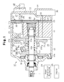
- variable displacement compressor of a vehicle air-conditioner of a first embodiment of the invention will be described with reference to Figs. 1, 2, and 3.
- a compressor 10 includes a cylinder block 11, a front housing member 12, which is fixed to the front end of the cylinder block 11, and a rear housing member 14, which is fixed to the rear end of the cylinder block 11 through a valve plate 13.
- the housing members 12, 14, the valve plate 13 and the cylinder block 11 are secured to each other with a plurality of bolts 10a (only one shown).
- a crank chamber 15 is defined between the cylinder block 11 and the front housing member 12.
- a drive shaft 16 is supported in the cylinder block 11 and the front housing member 12 with bearings.
- a lug plate 17 is fixed to the drive shaft 16 in the crank chamber 15. The lug plate 17 transmits thrust to an internal wall surface of the front housing member 12 through a thrust bearing 18.
- a swash plate 19, or cam plate includes an aluminum-based swash plate body 20 and an iron-based swash plate guide 21, and the swash plate body 20 is press fitted into the swash plate guide 21.
- burning between the swash plate 19 and an iron-based shoe 23a is inhibited.
- the weight of the swash plate 19 is limited.
- the swash plate guide 21 is provided with a through hole 21a, and the drive shaft 16 passes through the through hole 21a.
- a hinge mechanism 22 is located between the lug plate 17 and the swash plate 19. Therefore, the swash plate 19 rotates in synchronization with the lug plate 17 and the drive shaft 16, and the swash plate 19 can incline with respect to the drive shaft 16 while sliding on the drive shaft 16 in the axial direction.
- the swash plate 21 includes a counterweight 21b at a location that is opposite to the hinge mechanism 22 with respect to the drive shaft 16. Between the lug plate 17 and the swash plate guide 21 a spring 16a is fitted around the drive shaft 16. The spring 16a urges the swash plate 19 toward the cylinder block 11, that is, in the direction in which the inclination angle decreases.
- a plurality of cylinder bores 11a (only one shown in Fig. 1) is provided in the cylinder block 11 such that the bores 11a are positioned at equal angular intervals.
- a single-headed piston 23 is fitted in each of the cylinder bores 11a.
- the front openings of the cylinder bores 11a are closed by the valve plate 13, and a compressor chamber 11b is defined in each cylinder bore 11a.
- the volume of the compressor 11b varies depending on the position of the corresponding piston 23.
- Each piston 23 is connected to the periphery of the swash plate 19 through a pair of the shoes 23a. Accordingly, the rotational motion of the swash plate 19, which is produced by the rotation of the drive shaft 16, is converted to reciprocating motion of the pistons 23.
- the drive shaft 16 is connected to an engine 25 through a power transmission mechanism 24.
- the power transmission mechanism 24 may be a clutch mechanism (for example, an electromagnetic clutch), which connects and disconnects power transmission and is externally controlled.
- the power transmission mechanism 24 may be a clutchless (for example, the combination of a belt and a pulley).
- the present embodiment has a clutchless type power transmission mechanism 24.
- a suction chamber 26 and a substantially annular discharge chamber 27, which surrounds the suction chamber 26, are defined in the rear housing member 14.
- a suction port 28, a suction valve 29, which opens and closes the suction port 28, a discharge port 30, and a discharge valve 31, which opens and closes the discharge port 30, are formed in correspondence with each cylinder bore 11a.
- the suction chamber 26 and the discharge chamber 27 are connected to each other by an external refrigerant circuit 32.
- the cylinder block 11, the valve plate 13 and the rear housing member 14 are provided with an air-supply passage 33, which connects the crank chamber 15 and the discharge chamber 27, and a bleed passage 34, which connects the crank chamber 15 and the suction chamber 26.
- a control valve 35 is installed on the way of the supply passage 33.
- the control valve 35 is similar to the control valve disclosed in Japanese Unexamined Patent Publication No. Hei 9-268973, and includes a bellows, which moves in response to changes in the suction pressure, a solenoid, which produces electromagnetic force, and a valve mechanism, which controls the degree of opening of the supply passage 33 according to the displacement of the bellows and the electromagnetic force of the solenoid.
- the parts of the control valve 35 are not shown.
- the bellows are displaced so that the supply passage 33 is opened, and when the pressure in the suction chamber 26 is a predetermined value or more, the supply passage 33 is held in a closed state.
- the discharge displacement of the compressor is adjusted by controlling the pressure (crank pressure) Pc in the crank chamber with the control valve 35. That is, when the pressure in the suction chamber 26 is relatively low, the degree of opening of the control valve 35 is increased so that the crank pressure Pc is increased. Accordingly, the inclination angle (angle formed by a plane perpendicular to the drive shaft 16 and the swash plate 19) of the swash plate 19 is decreased so that the stroke of each piston 23 is decreased and the discharge displacement is reduced.
- the hinge mechanism 22 has two supporting arms 36 (only one is shown), which extend from a rear surface of the lug plate 17, a guide hole 37 formed in each of the supporting arms 36, and two guide pins 38, which are fixed to the swash plate 19.
- Each guide hole 37 is cylindrical.
- the guide pins 38 are parallel, and an imaginary plane that includes the axis of the drive shaft 16 lies between the pins 38.
- One pin 38 corresponds to each supporting arm 36.
- the guide pins 38 are identical in shape and size, and are symmetrical with respect to the previously mentioned imaginary plane.
- Each of the guide pins 38 includes a shaft portion 38a attached to the swash plate 19 and a spherical portion 38b formed at the distal end of the shaft portion 38a.
- the spherical portions 38b engage the guide holes 37.
- Each spherical portion 38b has a larger outer diameter than the shaft portion 38a, and the distal end of each spherical portion 38b is truncated along a plane. At least a portion of each spherical portion 38b is hollow.
- Each guide pin 38 is forged by use of, for example, a header or a former.
- a hollow chamber 38c in each guide pin 38 is opened at the distal end of the spherical portion 38b.
- the shape of the hollow chamber 38c can be appropriately selected. For example, any one of many shapes such as a first shape, in which the hollow chamber 38c extends to approximately the center of the spherical portion 38b as shown in Fig. 2(a), a second shape, in which the hollow chamber 38c extends to the shaft portion 38a as shown in Fig. 2(b), and a third shape, in which the hollow chamber 38c extends to the vicinity of the location where the shaft portion 38a joins with the swash plate guide 21 as shown in Fig. 2(c), can be selected.
- the masses of the guide pins 38 shown in Figs. 2(a), 2(b) and 2(c) decreases as indicated by the following inequality: Fig. 2(a) > Fig. 2(b) > Fig. 2(c).
- the shape of the swash plate 19 is like that of the swash plate disclosed in Japanese Unexamined Patent Publication, No. Hei 7-293429 (USP 5,573,379).
- Figs. 3(a) and 3(b) employ an xyz coordinate system.
- a vibration axis of the swash plate 19 is represented by S.
- the axis of the drive shaft 16, is represented by y.
- a z-axis is perpendicular to the plane of the sheet of Fig. 3(a) and is parallel to the vibration axis S.
- An x-axis is perpendicular to both the y and z axes.
- a point of intersection the x, y and z axes is defined as an origin point ⁇ .
- the operation of the compressor is as follows.
- the degree of opening of the control valve 35 is adjusted according to the cooling load.
- the opening degree of the control valve 35 is reduced, and the pressure (crank pressure Pc) in the crank chamber 15 is decreased as a result, which increases the inclination angle of the swash plate 19.
- the stroke of each piston 23 is increased accordingly, and the compressor 10 operates with a large displacement.
- the opening degree of the control valve 35 is increased and the pressure (crank pressure Pc) in the crank chamber 15 is increased so that the inclination angle of the swash plate 19 is decreased.
- the stroke of the piston 23 is decreased, and the compressor 10 operates with a small displacement.
- the moment that is generated by rotation of the swash plate 19 (the moment due to centrifugal force) is the product of inertia Ixy of the swash plate 19 with respect to the xz plane and the yz plane in the right-angled coordinate system (x, y, z) multiplied by the square of the angular velocity ⁇ of the drive shaft 16.
- y axis coincides with the axis of the drive shaft 16
- the z axis is parallel to the vibration shaft S
- the x axis is perpendicular to the y axis and the z axis.
- the distance L is increased by about 20%, as shown in Fig. 3(a), as compared with the swash plate 19 shown in Fig. 3(b), which is an entirely iron-based swash plate.
- the product of inertia Ixy of the swash plate 19 of Fig. 3(a) is significantly increased compared with the swash plate 19 of Fig. 3(b).
- the hollow chambers 38c are formed so that the masses of the front spherical portions 38b of the guide pins 38 are decreased, even if the mass of the guide pins 38 are the same, the product of inertia Ixy is smaller than that of a swash plate lacking the hollow chambers 38c. Further, the moment M based on the rotation of the swash plate 19 is smaller than the moment Mo of a conventional swash plate, as shown in Fig. 4. Thus, the crank pressure Pc necessary for changing the inclination angle of the swash plate 19 is reduced.
- This embodiment has the following effects.
- the second embodiment is not limited to the structure described above, and may be constructed as follows for example.
- the hollow chamber 38c of the guide pin 38 may be formed in the shaft 38a of the guide pin 38, as shown in Figs. 7(a) and 7(b).
- a hollow chamber 38c may be formed in the guide pin 38 and a slit 38d may be formed in the shaft portion 38a, as shown in Fig, 7(c).
- the outer diameter tolerance of the shaft portion 38a may be increased.
- the guide pin 43 may be formed such that a partition is formed in the hollow portion 43a as shown in Fig. 8(a).
- the ends of the pin 43 may be formed by solid bodies, as shown in Fig. 8(b), instead of the simple pipe shape of Fig. 5.
- the force on the guide pin 43 acts strongly on the ends of the guide pin 43.
- the strength of the guide pin 43 is improved.
- the swash plate 19 may be pivotally connected to a sleeve 39 that is fitted on the drive shaft 16, as in the second embodiment, through the supporting shafts 40.
- the swash plate 19 may be supported on the drive shaft 16 as in the first embodiment.
- a spherical sleeve may be fitted on the drive shaft 16, and the swash plate 19 may be pivotally supported on the outer surface of the spherical sleeve.
- the hinge mechanisms of Fig. 1 and 6 have two joints. That is, two pins 38 couple with two holes 37 in Fig. 1, and two arms 41 form joints in Fig. 6. Alternatively, each hinge may have just one joint. However, two sets are preferable from the viewpoints of rotational balance and stability in the driving power transmission.
- the swash plate 19 may be made of only one kind of metal, such as an iron based metal or the like. In this case, a press-fit margin is not needed, and the distance between the guide pin 38 and the xz plane can be decreased. Accordingly, the product of inertia Ixy can be further decreased by forming the guide pin 38 in a hollow shape.
- a surface treatment for example, aluminum spray coating
- the guide hole 44 may be formed in the swing arm 41, and the mounting holes 45 may be formed in the supporting arm 42.
- the guide pin 38 may be manufactured by cutting or casting.
- the present invention may be applied to a wobble type variable displacement compressor.
- a hinge mechanism (22) is positioned between a rotating support (17) and the cam plate (19).
- the hinge mechanism includes a guide pin (38), and the guide pin transfers the rotational motion of the rotating support (17) to the cam plate (19) and permits inclination of the cam plate.
- At least a part of the guide pin (38) is hollow.
Landscapes
- Engineering & Computer Science (AREA)
- Mechanical Engineering (AREA)
- General Engineering & Computer Science (AREA)
- Compressors, Vaccum Pumps And Other Relevant Systems (AREA)
- Rotary Pumps (AREA)
Abstract
Description
Further, when a check valve is provided downstream of the discharge port of the compressor, the valve opening pressure can be reduced and performance is consequently improved.
Claims (10)
- A variable displacement compressor comprising a housing including a cylinder bore(11a); a piston (23) accommodated in the cylinder bore; a drive shaft (16) supported by the housing; a rotating support (17) integrally fixed to the drive shaft; a cam plate (19) connected to the piston for converting rotational motion of the drive shaft to reciprocation of the piston, wherein the cam plate (19) inclines with respect to the drive shaft, and wherein the stroke of the piston (23) changes to vary the discharge displacement of the compressor when the inclination of the cam plate changes; and a hinge mechanism (22) positioned between the rotating support (17) and the cam plate (19), characterized by that the hinge mechanism (22) includes a guide pin (38) for transferring rotation of the rotating support (17) to the cam plate (19) and for permitting the inclination of the cam plate, wherein a part of the guide pin (22) is hollow.
- The compressor according to claim 1, characterized by that the hinge mechanism includes a supporting arm (42) extending from the rotating support toward the cam plate and a guide portion (37) provided in the support arm, the guide pin (38) comprising:
a shaft portion (38a), which is fixed to the cam plate, and a spherical portion (38b), which has a larger diameter than the shaft portion and is provided on the shaft portion, wherein the spherical portion (38b) engages the guide portion (37), and at least a part of the spherical portion (38b) is hollow. - The compressor according to claim 2, characterized by that the guide pin (38) has a hollow chamber that is open on the outer periphery of the spherical portion, wherein the hollow chamber extends substantially to the center of the spherical portion.
- The compressor according to claim 2, characterized by that the guide pin (38) has a hollow chamber that is open on the outer periphery of the spherical portion, wherein the hollow chamber extends to the shaft portion.
- The compressor according to claim 2, characterized by that a part of the shaft portion (38a) is embedded in the cam plate, and a part of the shaft portion (38a) is exposed from the cam plate (19), and wherein the guide pin has a hollow chamber that is open on the outer surface of the spherical portion, wherein the hollow chamber extends within the entire exposed portion of the shaft portion.
- The compressor according to claim 1, characterized by that the hinge mechanism comprises:a swing arm (41) extending from the cam plate (19) toward the rotating support (17);a supporting arm (42) on the rotating support (17);a guide hole (44) formed in one of the swing arm and the supporting arm; anda mounting hole (45) formed in the other of the swing arm and the supporting arm, wherein the guide pin is located within the guide hole and the mounting hole.
- The compressor according to claim 6, characterized by that the guide hole (44) is formed in the supporting arm (42) and the mounting hole (45) is formed in the swing arm (41).
- The compressor according to claim 7, characterized by that the swing arm is a first swing arm and the mounting hole is a first mounting hole, and the compressor further comprises a second swing arm and a corresponding second mounting hole, the first and second swing arms being arranged on opposite sides of the supporting arm (42), wherein the first mounting hole is coaxial with the second mounting hole, and end portions of the pin, which extend between the swing arms and the supporting arm, are solid.
- The compressor according to claim 1, characterized by that the guide pin (38) is manufactured by forging.
- The compressor according to claim 2, characterized by that the distal end portion of the spherical portion (38b) is truncated.
Applications Claiming Priority (2)
| Application Number | Priority Date | Filing Date | Title |
|---|---|---|---|
| JP2000114806 | 2000-04-17 | ||
| JP2000114806A JP2001295755A (en) | 2000-04-17 | 2000-04-17 | Guide pin of variable displacement compressor and variable displacement compressor |
Publications (2)
| Publication Number | Publication Date |
|---|---|
| EP1148239A2 true EP1148239A2 (en) | 2001-10-24 |
| EP1148239A3 EP1148239A3 (en) | 2004-02-25 |
Family
ID=18626548
Family Applications (1)
| Application Number | Title | Priority Date | Filing Date |
|---|---|---|---|
| EP01109145A Withdrawn EP1148239A3 (en) | 2000-04-17 | 2001-04-12 | Hinge mechanism for variable displacement compressor |
Country Status (6)
| Country | Link |
|---|---|
| US (1) | US20010029837A1 (en) |
| EP (1) | EP1148239A3 (en) |
| JP (1) | JP2001295755A (en) |
| KR (1) | KR20010096580A (en) |
| CN (1) | CN1318691A (en) |
| BR (1) | BR0101494A (en) |
Cited By (3)
| Publication number | Priority date | Publication date | Assignee | Title |
|---|---|---|---|---|
| WO2005124150A1 (en) * | 2004-06-16 | 2005-12-29 | Zexel Valeo Compressor Europe Gmbh | Axial piston compressor, in particular a compressor for the air conditioning system of a motor vehicle |
| EP1602829A3 (en) * | 2004-06-04 | 2009-09-30 | Valeo Compressor Europe GmbH | Swash plate compressor |
| US9765764B2 (en) | 2014-04-07 | 2017-09-19 | Hanon Systems | Hinge mechanism for a variable displacement compressor |
Families Citing this family (4)
| Publication number | Priority date | Publication date | Assignee | Title |
|---|---|---|---|---|
| JP2002031050A (en) * | 2000-07-17 | 2002-01-31 | Toyota Industries Corp | Compressor |
| JP5324936B2 (en) * | 2009-01-21 | 2013-10-23 | サンデン株式会社 | Variable capacity compressor and its minimum inclination setting method |
| JP6013768B2 (en) * | 2012-04-25 | 2016-10-25 | サンデンホールディングス株式会社 | Variable capacity compressor and manufacturing method thereof |
| KR102112214B1 (en) * | 2017-09-14 | 2020-05-19 | 한온시스템 주식회사 | Variable swash plate compressor |
Family Cites Families (3)
| Publication number | Priority date | Publication date | Assignee | Title |
|---|---|---|---|---|
| JP3060670B2 (en) * | 1991-11-29 | 2000-07-10 | 株式会社豊田自動織機製作所 | Variable displacement swash plate compressor |
| JP3082993B2 (en) * | 1992-05-12 | 2000-09-04 | 株式会社豊田自動織機製作所 | Variable capacity swash plate compressor |
| JP3182951B2 (en) * | 1992-12-28 | 2001-07-03 | 株式会社豊田自動織機製作所 | Clutchless swinging swash plate type variable displacement compressor |
-
2000
- 2000-04-17 JP JP2000114806A patent/JP2001295755A/en active Pending
-
2001
- 2001-03-06 KR KR1020010011359A patent/KR20010096580A/en not_active Abandoned
- 2001-04-10 US US09/829,853 patent/US20010029837A1/en not_active Abandoned
- 2001-04-12 EP EP01109145A patent/EP1148239A3/en not_active Withdrawn
- 2001-04-17 CN CN01119285A patent/CN1318691A/en active Pending
- 2001-04-17 BR BR0101494-3A patent/BR0101494A/en active Search and Examination
Cited By (4)
| Publication number | Priority date | Publication date | Assignee | Title |
|---|---|---|---|---|
| EP1602829A3 (en) * | 2004-06-04 | 2009-09-30 | Valeo Compressor Europe GmbH | Swash plate compressor |
| WO2005124150A1 (en) * | 2004-06-16 | 2005-12-29 | Zexel Valeo Compressor Europe Gmbh | Axial piston compressor, in particular a compressor for the air conditioning system of a motor vehicle |
| US8230773B2 (en) | 2004-06-16 | 2012-07-31 | Valeo Compressor Europe Gmbh | Axial piston compressor, in particular a compressor for the air conditioning system of a motor vehicle |
| US9765764B2 (en) | 2014-04-07 | 2017-09-19 | Hanon Systems | Hinge mechanism for a variable displacement compressor |
Also Published As
| Publication number | Publication date |
|---|---|
| EP1148239A3 (en) | 2004-02-25 |
| JP2001295755A (en) | 2001-10-26 |
| BR0101494A (en) | 2001-11-13 |
| CN1318691A (en) | 2001-10-24 |
| US20010029837A1 (en) | 2001-10-18 |
| KR20010096580A (en) | 2001-11-07 |
Similar Documents
| Publication | Publication Date | Title |
|---|---|---|
| US5706716A (en) | Variable displacement swash plate type compressor | |
| US6139282A (en) | Variable capacity refrigerant compressor with an aluminum cam plate means | |
| US5765464A (en) | Reciprocating pistons of piston-type compressor | |
| EP0844390B1 (en) | Swash plate type compressor using swash plate made of highly wear-resistant material | |
| EP0292288B1 (en) | Variable displacement compressor with biased inclined member | |
| US6186048B1 (en) | Variable displacement compressor | |
| US4979877A (en) | Wobble plate type refrigerant compressor | |
| US6547533B2 (en) | Axial movement restriction means for swash plate compressor and compressor assembly method | |
| US5231914A (en) | Variable displacement compressor | |
| EP1148241A2 (en) | Hinge mechanism for a variable displacement compressor | |
| US20010029837A1 (en) | Hinge mechanism for variable displacement compressor | |
| US4850811A (en) | Compressor with variable displacement mechanism | |
| EP0499343B1 (en) | Slant plate type compressor | |
| US6276904B1 (en) | Variable capacity refrigerant compressor having an inclination limiting means to interrupt compressive forces on a hinge mechanism | |
| EP1167760B1 (en) | Swash plate type compressor | |
| JP3084377B2 (en) | Compressor and single-ended piston for use in it | |
| JPH04279776A (en) | Variable capacity compressor | |
| JP2013245632A (en) | Variable-displacement compressor | |
| EP1039128A2 (en) | Swash plate type compressor | |
| JP2004108245A (en) | Variable displacement compressor | |
| US20060222513A1 (en) | Swash plate type variable displacement compressor | |
| EP1120567A2 (en) | Variable swash plate compressor | |
| JPS61218783A (en) | Variable capacity compressor | |
| JP2569696B2 (en) | Compressor | |
| US20020144591A1 (en) | Swash plate-type variable displacement compressors |
Legal Events
| Date | Code | Title | Description |
|---|---|---|---|
| PUAI | Public reference made under article 153(3) epc to a published international application that has entered the european phase |
Free format text: ORIGINAL CODE: 0009012 |
|
| 17P | Request for examination filed |
Effective date: 20010412 |
|
| AK | Designated contracting states |
Kind code of ref document: A2 Designated state(s): AT BE CH CY DE DK ES FI FR GB GR IE IT LI LU MC NL PT SE TR |
|
| AX | Request for extension of the european patent |
Free format text: AL;LT;LV;MK;RO;SI |
|
| RAP1 | Party data changed (applicant data changed or rights of an application transferred) |
Owner name: KABUSHIKI KAISHA TOYOTA JIDOSHOKKI |
|
| PUAL | Search report despatched |
Free format text: ORIGINAL CODE: 0009013 |
|
| AK | Designated contracting states |
Kind code of ref document: A3 Designated state(s): AT BE CH CY DE DK ES FI FR GB GR IE IT LI LU MC NL PT SE TR |
|
| AX | Request for extension of the european patent |
Extension state: AL LT LV MK RO SI |
|
| STAA | Information on the status of an ep patent application or granted ep patent |
Free format text: STATUS: THE APPLICATION IS DEEMED TO BE WITHDRAWN |
|
| 18D | Application deemed to be withdrawn |
Effective date: 20031103 |