EP1148216A2 - Cooling water passage structure for water-cooled type internal combustion engine - Google Patents
Cooling water passage structure for water-cooled type internal combustion engine Download PDFInfo
- Publication number
- EP1148216A2 EP1148216A2 EP01109545A EP01109545A EP1148216A2 EP 1148216 A2 EP1148216 A2 EP 1148216A2 EP 01109545 A EP01109545 A EP 01109545A EP 01109545 A EP01109545 A EP 01109545A EP 1148216 A2 EP1148216 A2 EP 1148216A2
- Authority
- EP
- European Patent Office
- Prior art keywords
- cooling water
- passage
- thermostat valve
- internal combustion
- combustion engine
- Prior art date
- Legal status (The legal status is an assumption and is not a legal conclusion. Google has not performed a legal analysis and makes no representation as to the accuracy of the status listed.)
- Granted
Links
- 239000000498 cooling water Substances 0.000 title claims abstract description 164
- 238000002485 combustion reaction Methods 0.000 title claims abstract description 23
- XLYOFNOQVPJJNP-UHFFFAOYSA-N water Substances O XLYOFNOQVPJJNP-UHFFFAOYSA-N 0.000 claims abstract description 56
- 238000010586 diagram Methods 0.000 description 8
- 239000000446 fuel Substances 0.000 description 6
- 230000000694 effects Effects 0.000 description 3
- 238000001816 cooling Methods 0.000 description 1
Images




Classifications
-
- F—MECHANICAL ENGINEERING; LIGHTING; HEATING; WEAPONS; BLASTING
- F01—MACHINES OR ENGINES IN GENERAL; ENGINE PLANTS IN GENERAL; STEAM ENGINES
- F01P—COOLING OF MACHINES OR ENGINES IN GENERAL; COOLING OF INTERNAL-COMBUSTION ENGINES
- F01P7/00—Controlling of coolant flow
- F01P7/14—Controlling of coolant flow the coolant being liquid
- F01P7/16—Controlling of coolant flow the coolant being liquid by thermostatic control
- F01P7/165—Controlling of coolant flow the coolant being liquid by thermostatic control characterised by systems with two or more loops
-
- F—MECHANICAL ENGINEERING; LIGHTING; HEATING; WEAPONS; BLASTING
- F02—COMBUSTION ENGINES; HOT-GAS OR COMBUSTION-PRODUCT ENGINE PLANTS
- F02M—SUPPLYING COMBUSTION ENGINES IN GENERAL WITH COMBUSTIBLE MIXTURES OR CONSTITUENTS THEREOF
- F02M31/00—Apparatus for thermally treating combustion-air, fuel, or fuel-air mixture
- F02M31/02—Apparatus for thermally treating combustion-air, fuel, or fuel-air mixture for heating
- F02M31/04—Apparatus for thermally treating combustion-air, fuel, or fuel-air mixture for heating combustion-air or fuel-air mixture
- F02M31/10—Apparatus for thermally treating combustion-air, fuel, or fuel-air mixture for heating combustion-air or fuel-air mixture by hot liquids, e.g. lubricants or cooling water
-
- F—MECHANICAL ENGINEERING; LIGHTING; HEATING; WEAPONS; BLASTING
- F01—MACHINES OR ENGINES IN GENERAL; ENGINE PLANTS IN GENERAL; STEAM ENGINES
- F01P—COOLING OF MACHINES OR ENGINES IN GENERAL; COOLING OF INTERNAL-COMBUSTION ENGINES
- F01P3/00—Liquid cooling
- F01P3/20—Cooling circuits not specific to a single part of engine or machine
-
- F—MECHANICAL ENGINEERING; LIGHTING; HEATING; WEAPONS; BLASTING
- F01—MACHINES OR ENGINES IN GENERAL; ENGINE PLANTS IN GENERAL; STEAM ENGINES
- F01P—COOLING OF MACHINES OR ENGINES IN GENERAL; COOLING OF INTERNAL-COMBUSTION ENGINES
- F01P7/00—Controlling of coolant flow
- F01P7/14—Controlling of coolant flow the coolant being liquid
- F01P7/16—Controlling of coolant flow the coolant being liquid by thermostatic control
-
- Y—GENERAL TAGGING OF NEW TECHNOLOGICAL DEVELOPMENTS; GENERAL TAGGING OF CROSS-SECTIONAL TECHNOLOGIES SPANNING OVER SEVERAL SECTIONS OF THE IPC; TECHNICAL SUBJECTS COVERED BY FORMER USPC CROSS-REFERENCE ART COLLECTIONS [XRACs] AND DIGESTS
- Y02—TECHNOLOGIES OR APPLICATIONS FOR MITIGATION OR ADAPTATION AGAINST CLIMATE CHANGE
- Y02T—CLIMATE CHANGE MITIGATION TECHNOLOGIES RELATED TO TRANSPORTATION
- Y02T10/00—Road transport of goods or passengers
- Y02T10/10—Internal combustion engine [ICE] based vehicles
- Y02T10/12—Improving ICE efficiencies
Definitions
- the present invention relates to a cooling water passage structure for a water-cooled type internal combustion engine, and particularly to a cooling water passage structure for a water-cooled type internal combustion engine such that the flow of cooling water through a hot water riser passage from a thermostat valve toward a carburetor can be caused and stopped assuredly without damaging the degree of freedom in laying out the passage and without complicating structure.
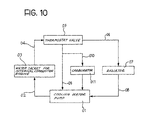
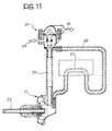
- Fig. 10 is a total structural diagram showing one example of a conventional cooling water passage structure for a water-cooled type internal combustion engine, and Fig. 11 is a partly omitted schematic view of the same.
- Cooling water is fed from a cooling water pump 01 through a passage 02 to a water jacket 03 for an internal combustion engine, where it cools the engine while itself being heated.
- the cooling water is then fed through passages 04 and 06 to a radiator 07, where it is cooled, before being fed through a passage 08 back to an inlet of the cooling water pump 01.
- a thermostat valve 05 is provided between the water jacket 03 and the radiator 07.
- a by-pass passage 09 extending from the thermostat valve 05 to the inlet of the cooling water pump 01 and a hot water riser passage 010 extending from the thermostat valve 05 via a carburetor 011 to the inlet of the cooling water pump 01 are provided.
- Fig. 12 is a detailed vertical sectional side view of the thermostat valve 05 shown in Figs. 10 and 11.
- numeral 050 denotes a cooling water intake portion
- 051 denotes a first cooling water discharge portion
- 052 denotes a second cooling water discharge portion
- 053 denotes a third cooling water discharge portion.
- the third cooling water discharge portion 053 is branched from the second cooling water discharge portion 052.
- the passage 04 in Fig. 10 is connected to the cooling water intake portion 50, and cooling water is introduced there from the water jacket 03 for the internal combustion engine.
- the passage 06 extending to the radiator 07 is connected to the first cooling water discharge portion 051.
- the by-pass passage 09 extending to the cooling water pump 01 is connected to the second cooling water discharge portion 052, and the hot water riser passage 010 extending to the carburetor 011 is connected to the third cooling water discharge portion 053.
- the temperature of cooling water flowing into the thermostat valve 05 is detected by a temperature-sensitive portion 056 in which a wax or the like is contained.
- a first valve 054 is closed, whereby the cooling water intake portion 050 and the first cooling water discharge portion 051 are shut off from each other.
- the first valve 054 is opened so that the cooling water intake portion 050 and the first cooling water discharge portion 051 are communicated with each other, whereby the cooling water heated to a high temperature at the water jacket 03 of the internal combustion engine is supplied to the radiator 07, where it is cooled.
- a second valve 055 is provided at the second cooling water discharge portion 052 in a lower portion of the thermostat valve 05, and is closed and opened in reverse conjunction with the opening and closure of the first valve 054. Therefore, in the condition where the temperature of the cooling water is at or below the predetermined temperature, the second valve 055 is opened so that the cooling water intake portion 050 is communicated with the second cooling water discharge portion 052 and the third cooling water discharge portion 053; on the other hand, when the temperature of the cooling water is raised to or above the predetermined temperature, the second valve 055 is closed so that the cooling water intake portion 050 is shut off from the second cooling water discharge portion 052 and the third cooling water discharge portion 053.
- the cooling water heated in the water jacket 03 is supplied into a jacket for the carburetor 011, where it heats the portions near a low-speed fuel supply port in the carburetor 011, whereby the low-speed fuel supply port is protected from icing.
- the inlet of the hot water riser passage 010, or the third cooling water discharge portion 053, is branched from the inlet of the by-pass passage 09, or the second cooling water discharge portion 052; therefore, when the second valve 055 of the thermostat valve 05 opens and closes the inlet of the bottom by-pass passage 09, the inlet of the hot water riser passage 010 is indirectly opened and closed. Namely, there is no mechanism for directly opening and closing the inlet of the hot water riser passage 010.
- the position of the hot water riser passage 010 must be so selected that there is no pressure difference between the by-pass passage 09 and the hot water riser passage 010, so that there is no freedom in laying out the hot water riser passage 010.
- a cooling water passage structure for a water-cooled type internal combustion engine comprising a cooling water pump provided between a water jacket for the internal combustion engine and a radiator, a thermostat valve for controlling the quantity of cooling water circulated, and a by-pass passage through which the cooling water is circulated without being circulated via the radiator during when it is cold, wherein one end of a hot water riser passage disposed in parallel with the by-pass passage and extending via a carburetor is communicated with a port (intake port or discharge port) of the cooling water pump, and the other end is communicated with the thermostat valve independently from a by-pass passage port (inflow port or outflow port) opening and closing portion of the thermostat valve.
- the invention as set forth in claim 1 is constituted as described above, there is no need to take into account the pressure balance between the by-pass passage and the hot water riser passage or the like. Therefore, the flow of cooling water through the hot water riser passage can be caused and stopped assuredly without damaging the degree of freedom in laying out the hot water riser passage. Namely, the degree of freedom in laying out the hot water riser passage is enhanced.
- the invention as set forth in claim 2 is characterized in that a port of the by-pass passage and a port of the hot water riser passage in the thermostat valve are opened and closed by the same valve body.
- the invention as set forth in claim 2 is constituted as described above, there is an advantage in cost, weight and space, as compared with the case where a separate opening and closing means is provided for the hot water riser passage in order to assuredly cause and stop the flow of cooling water through the hot water riser passage.
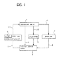
- Fig. 1 is a total structural diagram showing one embodiment of the present invention
- Fig. 2 is a partly omitted schematic view of the same.
- Cooling water is fed from a cooling water pump 1 through a passage 2 to a water jacket 3 for an internal combustion engine, where it cools the engine while itself being heated. Then, the cooling water flows through passage 4 and 6 to a radiator 7, where it is cooled, before flowing through a passage 8 back to an inlet of the cooling water pump 1.
- a thermostat valve 5 is provided between the water jacket 3 and the radiator 7.
- a by-pass passage 9 extending from the thermostat valve 5 to an inlet of the cooling water pump 1 and a hot water riser passage 10 extending from the thermostat valve 5 via a carburetor 11 to an inlet of the cooling water pump 1 are provided.
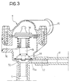
- Fig. 3 is a detailed vertical sectional side view showing the condition where a radiator-side outlet of the thermostat valve 5 in Figs. 1 and 2 is opened
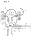
- Fig. 4 is a detailed vertical sectional side view showing the condition where the radiator-side outlet is closed.
- numeral 50 denotes a cooling water intake portion
- 51 denotes a cooling water discharge portion
- 52 denotes a second cooling water discharge portion
- 53 denotes a third cooling water discharge portion.
- the passage 4 in Fig. 1 is connected to the cooling water intake portion 50, and cooling water is introduced from the water jacket 3 for the internal combustion engine.
- a passage 6 extending to the radiator 7 is connected to the first cooling water discharge portion 51.
- a by-pass passage 9 extending to the cooling water pump 1 is connected to the second cooling water discharge portion 52, and a hot water riser passage 10 extending to a carburetor 11 is connected to the third cooling water discharge portion 53.
- the third cooling water discharge portion 53 is communicated with the cooling water intake portion 50 via a through-hole 53a.
- the second cooling water discharge portion 52 and the third cooling water discharge portion 53 are independent from each other, instead of the conventional structure in which one of them is branched from the other.
- the temperature of the cooling water flowing into the thermostat valve 5 is detected by a temperature-sensitive portion 56 in which a wax or the like is contained.
- a first valve 54 is closed, whereby the cooling water intake portion 50 and the first cooling water discharge portion 51 are shut off from each other.
- the first valve 54 is opened to communicate the cooling water intake portion 50 with the first cooling water discharge portion 51, whereby the cooling water heated to a high temperature at the water jacket 3 of the internal combustion engine is supplied to the radiator 7, where it is cooled.
- a second valve 55 is provided at the second cooling water discharge portion 52 and the third cooling water discharge portion 53, and is closed and opened in reverse conjunction with the opening and closure of the first valve 54. Therefore, in the condition where the temperature of the cooling water is not higher than the predetermined temperature, the second valve 55 is opened, whereby the cooling water intake portion 50 is communicated with the second cooling water discharge portion 52 and the third cooling water discharge portion 53. On the other hand, when the temperature of the cooling water is raised to or above the predetermined temperature, the second valve 55 is closed, whereby the cooling water intake portion 50 is shut off from the second cooling water discharge portion 52 and the third cooling water discharge portion 53.
- the cooling water heated in the above-mentioned water jacket 3 is supplied to a jacket for the carburetor 11, to heat the portions near a low-speed fuel supply port in the carburetor 11, whereby the low-speed fuel supply port is protected from icing.
- the second cooling water discharge portion 52 and the third cooling water discharge portion 53 are provided independently from each other, instead of the conventional structure in which one of them is branched from the other, so that there is no need for taking into account the pressure balance between the by-pass passage 9 and the hot water riser passage 10 or the like. Therefore, the flow of the cooling water in the hot water riser passage 10 can be caused and stopped assuredly without damaging the degree of freedom in laying out the hot water riser passage 10. Namely, the degree of freedom in laying out the hot water riser passage 10 is enhanced.
- the second cooling water discharge portion 52 and the third cooling water discharge portion 53 are simultaneously opened and closed by the same valve body (the second valve 55).
- the second valve 55 the same valve body
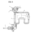
- a thermo-valve 12 for exclusive use for the hot water riser passage 10 is provided as shown in Fig. 9 so that the flow of cooling water in the hot water riser passage 10 can be assuredly caused and stopped.
- Fig. 5 is a vertical sectional side view of a thermostat valve according to a second embodiment of the present invention.
- a valve body of a second valve 55 is provided with a small through-hole 55a for communication between a cooling water intake portion 50 and a second cooling water discharge portion 52.
- Other arrangements are the same as in the first embodiment, so that the same components are denoted by the same numerals as in the first embodiments.
- the cooling water intake portion 50 and the second cooling water discharge portion 52 are always communicated with each other via the through-hole 55a, and a small quantity of cooling water always flows through the by-pass passage 9. Therefore, where it is desired that a small quantity of the cooling water is kept flowing through the by-pass passage 9 even when the second valve 55 of the thermostat valve 5 is closed, the third cooling water discharge portion 53, or an inlet of the hot water riser passage 10, can be closed independently. Accordingly, flows of water through the two passages can be controlled by one valve.
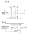
- Fig. 6 is a total structural diagram showing a third embodiment of the present invention.
- the invention has been applied to a cooling water circulating passage in which cooling water from a cooling water pump flows sequentially through the water jacket and the radiator back into the inlet of the cooling water pump.
- the invention is applied to a cooling water circulating passage in which cooling water from the cooling water pump 1 flows sequentially through the radiator 7 and the water jacket 3 back into the inlet of the cooling water pump 1.
- Fig. 7 is a total structural diagram showing a fourth embodiment of the present invention
- Fig. 8 is a detailed vertical sectional side view of a thermostat valve 15 in Fig. 7.
- a passage for feeding the cooling water from a water jacket 3 for an internal combustion engine directly to a radiator 7 and a passage extending from the water jacket 3 to a thermostat valve 15 via a carburetor 11 are provided.
- a cooling water discharge portion 150 is connected to an intake port of the cooling water pump 1
- a first cooling water intake portion 151 is connected to a cooling water outlet of the radiator 7
- a second cooling water intake portion 152 is connected to a cooling water outlet of the water jacket 3 for the internal combustion engine
- a third cooling water intake portion 153 is connected to a cooling water outlet of the carburetor 11.
- the temperature of the cooling water flowing into the thermostat valve 15 is detected by a temperature-sensitive portion 156 in which a wax or the like is contained.
- a first valve 154 is closed, whereby the cooling water discharge portion 150 and the first cooling water intake portion 151 are shut off from each other.
- the first valve 154 is opened to communicate the first cooling water intake portion 151 with the cooling water discharge portion 150, so that the cooling water heated to a high temperature at the water jacket 3 of the internal combustion engine is supplied to the radiator 7, where it is cooled.
- a second valve 155 is provided at the second cooling water intake portion 152 and a third cooling water intake portion 153, and is closed and opened in reverse conjunction with the opening and closure of the first valve 154. Therefore, where the temperature of the cooling water is not higher than the predetermined temperature, the second valve 155 is opened, whereby the cooling water discharge portion 150 is communicated with the second cooling water intake portion 152 and the third cooling water intake portion 153; on the other hand, when the temperature of the cooling water is raised to or above the predetermined temperature, the second valve 155 is closed, whereby the cooling water discharge portion 150 is shut off from the second cooling intake portion 152 and the third cooling water intake portion 153.
- the cooling water heated in the water jacket 3 is supplied to a jacket for the carburetor 11, to heat the portions near a low-speed fuel supply port in the carburetor 11, whereby the low-speed fuel supply port is protected from icing.
- 01, 1 cooling water pump; 02, 2: passage; 03, 3: water jacket; 04, 4: passage; 05, 5, 15: thermostat valve; 06, 6: passage; 07, 7: radiator; 08, 8: passage; 09, 9: by-pass passage; 010, 10: hot water riser passage; 011, 11: carburetor; 050, 50: cooling water intake portion; 051, 51: first cooling water discharge portion; 052, 52: second cooling water discharge portion; 053, 53: third cooling water discharge portion; 53a: through-hole; 054, 54, 154: first valve; 055, 55, 155: second valve; 55a: through-hole; 056, 56, 156: temperature-sensitive portion; 150: cooling water discharge portion; 151: first cooling water intake portion; 152: second cooling water intake portion; 153: third cooling water intake portion;
Landscapes
- Engineering & Computer Science (AREA)
- Chemical & Material Sciences (AREA)
- Combustion & Propulsion (AREA)
- Mechanical Engineering (AREA)
- General Engineering & Computer Science (AREA)
- Temperature-Responsive Valves (AREA)
Abstract
[Solving means] A cooling water passage structure comprising a cooling water pump (1) provided between a water jacket (3) for an internal combustion engine and a radiator (7), a thermostat valve (5) for controlling the quantitiy of cooling water circulated, and a by-pass passage (9) through which the cooling water is circulated without being circulated via the radiator (7) during when it is cold, wherein one end of a hot water riser passage disposed in parallel with the by-pass passage (9) and extending via a carburetor (11) is communicated with a port of the cooling water pump (1), and the other end is communicated with the thermostat valve (5) independently from an opening and closing portion of the thermostat valve for a port of the by-pass passage.
Description
Claims (2)
- A cooling water passage structure for a water-cooled type internal combustion engine comprising a cooling water pump provided between a water jacket for said internal combustion engine and a radiator, a thermostat valve for controlling the quantity of cooling water circulated, and a by-pass passage through which said cooling water is circulated without being circulated via said radiator during when it is cold, wherein one end of a hot water riser passage disposed in parallel with said by-pass passage and extending via a carburetor is communicated with a port of said cooling water pump, and the other end is communicated with said thermostat valve independently from a by-pass passage port opening and closing portion of said thermostat valve.
- The cooling water passage structure for a water-cooled type internal combustion engine, wherein a port of said by-pass passage and a port of said hot water riser passage in said thermostat valve are opened and closed by the same valve body.
Applications Claiming Priority (2)
| Application Number | Priority Date | Filing Date | Title |
|---|---|---|---|
| JP2000115415 | 2000-04-17 | ||
| JP2000115415A JP4357693B2 (en) | 2000-04-17 | 2000-04-17 | Cooling water passage structure for water-cooled internal combustion engine |
Publications (3)
| Publication Number | Publication Date |
|---|---|
| EP1148216A2 true EP1148216A2 (en) | 2001-10-24 |
| EP1148216A3 EP1148216A3 (en) | 2003-02-05 |
| EP1148216B1 EP1148216B1 (en) | 2006-09-06 |
Family
ID=18627059
Family Applications (1)
| Application Number | Title | Priority Date | Filing Date |
|---|---|---|---|
| EP01109545A Expired - Lifetime EP1148216B1 (en) | 2000-04-17 | 2001-04-17 | Cooling water passage structure for water-cooled type internal combustion engine |
Country Status (5)
| Country | Link |
|---|---|
| EP (1) | EP1148216B1 (en) |
| JP (1) | JP4357693B2 (en) |
| CN (1) | CN1139721C (en) |
| ES (1) | ES2190334B1 (en) |
| TW (1) | TW482247U (en) |
Families Citing this family (2)
| Publication number | Priority date | Publication date | Assignee | Title |
|---|---|---|---|---|
| FR2832187B1 (en) * | 2001-11-13 | 2005-08-05 | Valeo Thermique Moteur Sa | THERMAL ENERGY MANAGEMENT SYSTEM DEVELOPED BY A MOTOR VEHICLE THERMAL MOTOR |
| US20090183696A1 (en) * | 2008-01-18 | 2009-07-23 | O'flynn Kevin P | Liquid cooling system for internal combustion engine |
Family Cites Families (4)
| Publication number | Priority date | Publication date | Assignee | Title |
|---|---|---|---|---|
| US1550862A (en) * | 1918-06-04 | 1925-08-25 | Austin M Wolf | Internal-combustion engine and method of operating the same |
| FR2531489B1 (en) * | 1982-08-05 | 1987-04-03 | Marchal Equip Auto | COOLING DEVICE OF AN INTERNAL COMBUSTION ENGINE |
| US5079488A (en) * | 1988-02-26 | 1992-01-07 | General Electric Company | Electronically commutated motor driven apparatus |
| JP3838452B2 (en) * | 1996-12-17 | 2006-10-25 | 本田技研工業株式会社 | Cooling water passage structure of water-cooled internal combustion engine for small vehicles such as motorcycles |
-
2000
- 2000-04-17 JP JP2000115415A patent/JP4357693B2/en not_active Expired - Fee Related
-
2001
- 2001-04-12 CN CNB011220945A patent/CN1139721C/en not_active Expired - Fee Related
- 2001-04-13 TW TW090205818U patent/TW482247U/en not_active IP Right Cessation
- 2001-04-17 EP EP01109545A patent/EP1148216B1/en not_active Expired - Lifetime
- 2001-04-17 ES ES200100886A patent/ES2190334B1/en not_active Expired - Fee Related
Also Published As
| Publication number | Publication date |
|---|---|
| CN1321824A (en) | 2001-11-14 |
| EP1148216A3 (en) | 2003-02-05 |
| JP2001295646A (en) | 2001-10-26 |
| TW482247U (en) | 2002-04-01 |
| JP4357693B2 (en) | 2009-11-04 |
| CN1139721C (en) | 2004-02-25 |
| EP1148216B1 (en) | 2006-09-06 |
| ES2190334A1 (en) | 2003-07-16 |
| ES2190334B1 (en) | 2004-08-16 |
Similar Documents
| Publication | Publication Date | Title |
|---|---|---|
| US8739745B2 (en) | Cooling system and method | |
| US7263954B2 (en) | Internal combustion engine coolant flow | |
| CN101310097A (en) | Engine cooling medium circulating device | |
| CA2608485A1 (en) | Coolant controller for an internal combustion engine | |
| JP4432272B2 (en) | Internal combustion engine equipped with a heat storage device | |
| JP3185581B2 (en) | Internal combustion engine cooling system | |
| GB2245703A (en) | Engine cooling system | |
| JP3374715B2 (en) | Cooling water circulation device for internal combustion engine | |
| KR100482547B1 (en) | A system for cooling an engine | |
| EP1148216B1 (en) | Cooling water passage structure for water-cooled type internal combustion engine | |
| JP5853911B2 (en) | Cooling device for internal combustion engine | |
| JP2010151067A (en) | Cooling device for engine | |
| JPH11182241A (en) | Internal combustion engine cooling system | |
| JP3127695B2 (en) | Engine cooling system | |
| JP2006037874A (en) | Engine cooling system | |
| JPS6318773Y2 (en) | ||
| JP2560186B2 (en) | Water-cooled internal combustion engine cooling system | |
| JPH0571341A (en) | Cooling device of engine | |
| JPS64573B2 (en) | ||
| JPH0734173Y2 (en) | Cooling device for internal combustion engine | |
| JP2737611B2 (en) | Engine cooling system | |
| JP3032908B2 (en) | Engine cooling system | |
| JPH0291423A (en) | Cooler of supercharger attached on engine | |
| JPS6319586Y2 (en) | ||
| JPH0536989Y2 (en) |
Legal Events
| Date | Code | Title | Description |
|---|---|---|---|
| PUAI | Public reference made under article 153(3) epc to a published international application that has entered the european phase |
Free format text: ORIGINAL CODE: 0009012 |
|
| AK | Designated contracting states |
Kind code of ref document: A2 Designated state(s): AT BE CH CY DE DK ES FI FR GB GR IE IT LI LU MC NL PT SE TR |
|
| AX | Request for extension of the european patent |
Free format text: AL;LT;LV;MK;RO;SI |
|
| PUAL | Search report despatched |
Free format text: ORIGINAL CODE: 0009013 |
|
| AK | Designated contracting states |
Designated state(s): AT BE CH CY DE DK ES FI FR GB GR IE IT LI LU MC NL PT SE TR |
|
| AX | Request for extension of the european patent |
Extension state: AL LT LV MK RO SI |
|
| 17P | Request for examination filed |
Effective date: 20030717 |
|
| AKX | Designation fees paid |
Designated state(s): IT |
|
| REG | Reference to a national code |
Ref country code: DE Ref legal event code: 8566 |
|
| GRAP | Despatch of communication of intention to grant a patent |
Free format text: ORIGINAL CODE: EPIDOSNIGR1 |
|
| GRAS | Grant fee paid |
Free format text: ORIGINAL CODE: EPIDOSNIGR3 |
|
| GRAA | (expected) grant |
Free format text: ORIGINAL CODE: 0009210 |
|
| AK | Designated contracting states |
Kind code of ref document: B1 Designated state(s): IT |
|
| PG25 | Lapsed in a contracting state [announced via postgrant information from national office to epo] |
Ref country code: IT Free format text: LAPSE BECAUSE OF FAILURE TO SUBMIT A TRANSLATION OF THE DESCRIPTION OR TO PAY THE FEE WITHIN THE PRESCRIBED TIME-LIMIT;WARNING: LAPSES OF ITALIAN PATENTS WITH EFFECTIVE DATE BEFORE 2007 MAY HAVE OCCURRED AT ANY TIME BEFORE 2007. THE CORRECT EFFECTIVE DATE MAY BE DIFFERENT FROM THE ONE RECORDED. Effective date: 20060906 |
|
| PLBE | No opposition filed within time limit |
Free format text: ORIGINAL CODE: 0009261 |
|
| STAA | Information on the status of an ep patent application or granted ep patent |
Free format text: STATUS: NO OPPOSITION FILED WITHIN TIME LIMIT |
|
| 26N | No opposition filed |
Effective date: 20070607 |
|
| PGFP | Annual fee paid to national office [announced via postgrant information from national office to epo] |
Ref country code: IT Payment date: 20170420 Year of fee payment: 17 |
|
| PG25 | Lapsed in a contracting state [announced via postgrant information from national office to epo] |
Ref country code: IT Free format text: LAPSE BECAUSE OF NON-PAYMENT OF DUE FEES Effective date: 20180417 |