EP1148183A2 - Containment forms for building use - Google Patents
Containment forms for building use Download PDFInfo
- Publication number
- EP1148183A2 EP1148183A2 EP01201414A EP01201414A EP1148183A2 EP 1148183 A2 EP1148183 A2 EP 1148183A2 EP 01201414 A EP01201414 A EP 01201414A EP 01201414 A EP01201414 A EP 01201414A EP 1148183 A2 EP1148183 A2 EP 1148183A2
- Authority
- EP
- European Patent Office
- Prior art keywords
- elements
- forms
- building use
- use according
- straight
- Prior art date
- Legal status (The legal status is an assumption and is not a legal conclusion. Google has not performed a legal analysis and makes no representation as to the accuracy of the status listed.)
- Withdrawn
Links
Images

Classifications
-
- E—FIXED CONSTRUCTIONS
- E04—BUILDING
- E04G—SCAFFOLDING; FORMS; SHUTTERING; BUILDING IMPLEMENTS OR AIDS, OR THEIR USE; HANDLING BUILDING MATERIALS ON THE SITE; REPAIRING, BREAKING-UP OR OTHER WORK ON EXISTING BUILDINGS
- E04G13/00—Falsework, forms, or shutterings for particular parts of buildings, e.g. stairs, steps, cornices, balconies foundations, sills
- E04G13/06—Falsework, forms, or shutterings for particular parts of buildings, e.g. stairs, steps, cornices, balconies foundations, sills for stairs, steps, cornices, balconies, or other parts corbelled out of the wall
-
- E—FIXED CONSTRUCTIONS
- E04—BUILDING
- E04G—SCAFFOLDING; FORMS; SHUTTERING; BUILDING IMPLEMENTS OR AIDS, OR THEIR USE; HANDLING BUILDING MATERIALS ON THE SITE; REPAIRING, BREAKING-UP OR OTHER WORK ON EXISTING BUILDINGS
- E04G17/00—Connecting or other auxiliary members for forms, falsework structures, or shutterings
- E04G17/04—Connecting or fastening means for metallic forming or stiffening elements, e.g. for connecting metallic elements to non-metallic elements
- E04G17/045—Connecting or fastening means for metallic forming or stiffening elements, e.g. for connecting metallic elements to non-metallic elements being tensioned by wedge-shaped elements
Definitions
- the present invention relates to containment forms for building use, more particularly forms containing cement or concrete castings to make wall enclosures.
- Another drawback consists of the work required when casting is completed, to make some important elements in the wall, such as the drips, said work increasing the production time and the total costs.
- the object of the present invention is to remove the drawbacks belonging to the prior art systems.
- the present invention relates to containment forms for building use which is of practical use and easy to be carried out, allowing to obtain practically finished wall enclosures of a generally constant thickness even near corners or curvilinear stretches.
- the present invention provides for containment forms for building use comprising a plurality of elements operatively associated to each other, said elements being provided with connection means adapted to obtain a modular structure constituting said forms.
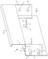
- Fig. 1 is a perspective view of an element belonging to the containment forms for building use according to the invention.
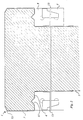
- Fig. 2 is a vertical sectional view of the forms of the invention in use.
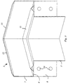
- Fig. 3 is a perspective view of a second element of the containment forms for building use of the invention.
- Fig. 4 is a perspective view of a further element of the forms of the invention.
- the containment forms 1 for building use consist of a plurality of elements 2, 3, 4 serially arranged one after the other on two general parallel rows.
- a first embodiment of said elements consists of a straight element 2 having a cross sectional shape generally comprising a first straight length 5, a second straight length 6 at right angles to the first length and a third straight length 7 perpendicular to the second length 6.
- connection means to join two elements where the plate at one end has two pins 9 corresponding to two holes 10 provided on the plate 8 of the other end, but other combinations are also possible.
- Said projection may have any suitable cross sectional shape such as a polygonal open shape, a circular shape and so forth, preferably a triangular shape.
- the surface of the first length 5 is also provided with matching means to keep constant the spacing of two parallel rows, each row consisting of a plurality of elements making a stretch of said forms 1.
- said matching means may consist of a couple of holes 12, each hole being connected on one side with a generally straight element 13 having another hole 14 adapted to receive conventional blocking means not shown in the drawings for fixing for instance a spacing rod between two straight elements 2 parallel to one another.
- the third straight length 7 of the cross sectional shape of the forms at the opposite end relative to the junction with said second length 6, is provided with a further straight piece 15 inclined relative to said third length 7 by an angle greater than 90 degrees.
- a second embodiment of said elements constituting said forms 1 consists of an angular element 3 adapted to connect elements at the points of the form 1 having a corner.
- Said second embodiment generally comprises the same parts of said element 2.
- said length 5, 6 and 7 of the cross sectional shape belong to three couples of plain surfaces mutually intersecting to define the angular element 3.
- connection means may consist of pins 9 and holes 10 as for instance shown in Fig. 3, while the matching means of the straight element 2 may be omitted according to the needs.
- a third embodiment of said elements constituting the forms 1 according to the invention consists of a curvilinear element 4 also comprising the same parts of the straight element 2, where the lengths 5, 6 and 7 of the cross sectional shape belong to curvilinear surfaces instead of plain surfaces of said element 2.
- the matching means may be omitted according to the needs as for the angular element 3.
- Said elements 2, 3, 4 are preferably made of stainless steel, galvanized sheet iron or PVC but other materials such as aluminum alloys, polycarbonate and wood may also be provided.
- the containment forms for building use of the invention consisting of said plurality of elements 2, 3, 4 are used as follows. Having chosen the area where the wall enclosure should be made, said area is bounded by a plurality of elements 2, 3, 4 according to needs, connected to one another by pins 9 and holes 10 so as to make a modular structure of the forms. Two parallel rows of elements 2, 3, 4 will be generally arranged at predetermined distance, said distance being determined by suitable spacing rods fixed to said matching means.
- said wall enclosure will advantageously have the requested thickness and a longitudinal development very close to the theoretical design, in view of the use of said spacing rods fixed to the matching means and of the elements 2, 3 and 4 each having the required different geometrical shape respectively.
Abstract
Description
- The present invention relates to containment forms for building use, more particularly forms containing cement or concrete castings to make wall enclosures.
- In many constructions either dwelling houses or factories, office buildings and the like, almost always there is an outer fence resting on a wall enclosure, which in this way has not only the function of defining the boundary of the property.
- In order to make said wall enclosures forms are known which are mainly made of wood, arranged parallel to one another to contain the concrete casting.
- Although these forms solve the mentioned technical problem, they have however several drawbacks.
- These forms have problems of connection between the lengths required to contain a complete wall enclosure, more particularly in case of bends or corners.
- Another drawback consists of the work required when casting is completed, to make some important elements in the wall, such as the drips, said work increasing the production time and the total costs.
- Another serious drawback is the almost practical impossibility to obtain wall enclosures with a really constant thickness. Indeed with the known forms, a constant cross sectional spacing of the forms is not warranted by any device or special element, but depends only on the ability and professional experience of the building workers.
- The object of the present invention is to remove the drawbacks belonging to the prior art systems.
- Therefore the present invention relates to containment forms for building use which is of practical use and easy to be carried out, allowing to obtain practically finished wall enclosures of a generally constant thickness even near corners or curvilinear stretches.
- Briefly the present invention provides for containment forms for building use comprising a plurality of elements operatively associated to each other, said elements being provided with connection means adapted to obtain a modular structure constituting said forms.
- The containment forms for building use according to the invention are characterized by the features recited in claim 1.
- Further advantageous features are recited in the dependent claims.
- Other features and the various details of the containment forms for building use according to the invention will be better understood by reading the following description with reference to the accompanying drawings in which a preferred embodiment is shown as an illustrative but non-limiting example.
- Fig. 1 is a perspective view of an element belonging to the containment forms for building use according to the invention.
- Fig. 2 is a vertical sectional view of the forms of the invention in use.
- Fig. 3 is a perspective view of a second element of the containment forms for building use of the invention.
- Fig. 4 is a perspective view of a further element of the forms of the invention.
- With reference now to the above mentioned figures of the drawings, the containment forms 1 for building use consist of a plurality of
elements 2, 3, 4 serially arranged one after the other on two general parallel rows. - A first embodiment of said elements consists of a straight element 2 having a cross sectional shape generally comprising a first
straight length 5, a secondstraight length 6 at right angles to the first length and a thirdstraight length 7 perpendicular to thesecond length 6. - Between the
lengths flat plate 8 having connection means to join two elements, where the plate at one end has twopins 9 corresponding to twoholes 10 provided on theplate 8 of the other end, but other combinations are also possible. - On the
second length 6 perpendicular to bothlengths projection 11 for carrying out the drip when casting the concrete. Said projection may have any suitable cross sectional shape such as a polygonal open shape, a circular shape and so forth, preferably a triangular shape. - The surface of the
first length 5 is also provided with matching means to keep constant the spacing of two parallel rows, each row consisting of a plurality of elements making a stretch of said forms 1. - More particularly said matching means may consist of a couple of
holes 12, each hole being connected on one side with a generallystraight element 13 having anotherhole 14 adapted to receive conventional blocking means not shown in the drawings for fixing for instance a spacing rod between two straight elements 2 parallel to one another. - The third
straight length 7 of the cross sectional shape of the forms at the opposite end relative to the junction with saidsecond length 6, is provided with a furtherstraight piece 15 inclined relative to saidthird length 7 by an angle greater than 90 degrees. - A second embodiment of said elements constituting said forms 1 consists of an angular element 3 adapted to connect elements at the points of the form 1 having a corner.
- Said second embodiment generally comprises the same parts of said element 2. However in this case said
length - Also in this case the
plates 8 are provided with connection means that may consist ofpins 9 andholes 10 as for instance shown in Fig. 3, while the matching means of the straight element 2 may be omitted according to the needs. - A third embodiment of said elements constituting the forms 1 according to the invention consists of a
curvilinear element 4 also comprising the same parts of the straight element 2, where thelengths - Said
elements 2, 3, 4 are preferably made of stainless steel, galvanized sheet iron or PVC but other materials such as aluminum alloys, polycarbonate and wood may also be provided. - The containment forms for building use of the invention consisting of said plurality of
elements 2, 3, 4 are used as follows. Having chosen the area where the wall enclosure should be made, said area is bounded by a plurality ofelements 2, 3, 4 according to needs, connected to one another bypins 9 andholes 10 so as to make a modular structure of the forms. Two parallel rows ofelements 2, 3, 4 will be generally arranged at predetermined distance, said distance being determined by suitable spacing rods fixed to said matching means. - Concrete casting is then carried out and a construction like that illustrated in the sectional view of Fig. 2 will be obtained. The upper portion of the casting contained by the
lengths 15, will be subsequently worked or leveled as required for instance by a wood strickle. - In this way once the forms are removed, the wall enclosure will be practically finished because it is already provided with the drips made by means of the
projections 11. - Moreover said wall enclosure will advantageously have the requested thickness and a longitudinal development very close to the theoretical design, in view of the use of said spacing rods fixed to the matching means and of the
elements 2, 3 and 4 each having the required different geometrical shape respectively. - It is to be understood that many modifications, adaptations, integrations, variations and substitutions may be made to the embodiment hereinbefore described as an illustrative and non-limiting example, however without departing from the scope of the present invention as defined in the appended claims.
Claims (12)
- Containment forms for building use comprising a plurality of elements (2, 3, 4) operatively associated to each other, characterized in that said elements are provided with connection means adapted to obtain a modular structure making said forms.
- The containment forms for building use according to claim 1), characterized in that said elements consist of straight elements (2), angular elements (3) and curvilinear elements (4).
- The containment forms for building use according to claim 2), characterized in that said elements (2, 3, 4) have a cross sectional shape comprising a first straight length (5) followed by a second straight length (6) at right angles to the first length (5) and a third straight length (7) perpendicular to said second length (6).
- The containment forms for building use according to claim 3), characterized in that between said first (5) and second (6) length at each end of said elements (2, 3, 4) there is a flat plate (8) provided with said connection means to join two elements (2, 3, 4) to each other.
- The containment forms for building use according to claim 4) characterized in that said connection means comprise on each plate (8) either a couple of pins (9) or a corresponding couple of holes (10).
- The containment forms for building use according to claim 3), characterized in that said second straight length (6) is provided with a projection (11) to define the shape of a drip.
- The containment forms for building use according to claim 3), characterized in that the cross sectional surface constituting said first straight length (5) is provided with matching means to keep constant the distance between two parallel rows each consisting of a plurality of said elements (2, 3, 4) making a stretch of said forms (1).
- The containment forms for building use according to claim 7), characterized in that said matching means comprise a couple of holes (12) each being connected at one side with a straight element (13) having a further hole (14) adapted to receive blocking means to fix a spacing rod between two elements (2, 3, 4) parallel to each other.
- The containment forms for building use according to claim 3), characterized in that the third straight length (7) of the cross sectional shape at the opposite end relative to the junction with said second straight length (6), is provided with a further straight piece (15) inclined relative to said third straight length (7) at an angle greater then 90 degrees.
- The containment forms for building use according to claim 3), characterized in that said straight lengths (5, 6, 7) of the cross sectional shape of said angular element (3) belong to three couples of plain surfaces intersecting with each other so as to define said angular element (3).
- The containment forms for building use according to claim 3), characterized in that said straight lengths (5, 6, 7) of the cross sectional shape of said curvilinear element (4) belong to curvilinear surfaces.
- The containment forms for building use according to claim 1), characterized in that said plurality of elements (2, 3, 4) is alternatively made of stainless steel, galvanized sheet iron, PVC, aluminum alloys, polycarbonate and wood.
Applications Claiming Priority (2)
| Application Number | Priority Date | Filing Date | Title |
|---|---|---|---|
| IT2000MI000257 IT250250Y1 (en) | 2000-04-21 | 2000-04-21 | CONTAINMENT ARMOR FOR CONSTRUCTION USE |
| ITMI000257U | 2000-04-21 |
Publications (2)
| Publication Number | Publication Date |
|---|---|
| EP1148183A2 true EP1148183A2 (en) | 2001-10-24 |
| EP1148183A3 EP1148183A3 (en) | 2004-01-07 |
Family
ID=11444029
Family Applications (1)
| Application Number | Title | Priority Date | Filing Date |
|---|---|---|---|
| EP01201414A Withdrawn EP1148183A3 (en) | 2000-04-21 | 2001-04-19 | Containment forms for building use |
Country Status (2)
| Country | Link |
|---|---|
| EP (1) | EP1148183A3 (en) |
| IT (1) | IT250250Y1 (en) |
Cited By (1)
| Publication number | Priority date | Publication date | Assignee | Title |
|---|---|---|---|---|
| FR2879633A1 (en) * | 2004-12-21 | 2006-06-23 | Francois Paul Six | Permanent formwork device for construction of house, has casings arranged directly in bottom of trench or on pile shoe and connected with each other by crossbars that are positioned in housing to maintain spacing between casings |
Citations (8)
| Publication number | Priority date | Publication date | Assignee | Title |
|---|---|---|---|---|
| US2251775A (en) * | 1940-01-15 | 1941-08-05 | Arrighini Artil | Concrete form |
| US2602983A (en) * | 1947-09-30 | 1952-07-15 | Arthur E Troiel | Wall opening form |
| US2663925A (en) * | 1950-06-02 | 1953-12-29 | Binghamton Metal Forms Inc | Construction form |
| US3288427A (en) * | 1963-07-10 | 1966-11-29 | Pluckebaum Paul | Assemblable formwork for reinforced concrete structures |
| AP334A (en) * | 1991-10-01 | 1994-04-26 | Hendrik Petrus Botes | Shuttering for building construction. |
| US5882540A (en) * | 1996-11-12 | 1999-03-16 | Farrington; Albert J. | Wall construction apparatus and methodology |
| DE19805473A1 (en) * | 1998-02-11 | 1999-08-12 | Martin Dipl Ing Gruetzner | Multi-way shuttering system for ceiling and wall hollow spaces |
| GB2340530A (en) * | 1998-08-12 | 2000-02-23 | Ozdemir Keskin | Aluminium kit formwork composite building system |
-
2000
- 2000-04-21 IT IT2000MI000257 patent/IT250250Y1/en active
-
2001
- 2001-04-19 EP EP01201414A patent/EP1148183A3/en not_active Withdrawn
Patent Citations (8)
| Publication number | Priority date | Publication date | Assignee | Title |
|---|---|---|---|---|
| US2251775A (en) * | 1940-01-15 | 1941-08-05 | Arrighini Artil | Concrete form |
| US2602983A (en) * | 1947-09-30 | 1952-07-15 | Arthur E Troiel | Wall opening form |
| US2663925A (en) * | 1950-06-02 | 1953-12-29 | Binghamton Metal Forms Inc | Construction form |
| US3288427A (en) * | 1963-07-10 | 1966-11-29 | Pluckebaum Paul | Assemblable formwork for reinforced concrete structures |
| AP334A (en) * | 1991-10-01 | 1994-04-26 | Hendrik Petrus Botes | Shuttering for building construction. |
| US5882540A (en) * | 1996-11-12 | 1999-03-16 | Farrington; Albert J. | Wall construction apparatus and methodology |
| DE19805473A1 (en) * | 1998-02-11 | 1999-08-12 | Martin Dipl Ing Gruetzner | Multi-way shuttering system for ceiling and wall hollow spaces |
| GB2340530A (en) * | 1998-08-12 | 2000-02-23 | Ozdemir Keskin | Aluminium kit formwork composite building system |
Cited By (1)
| Publication number | Priority date | Publication date | Assignee | Title |
|---|---|---|---|---|
| FR2879633A1 (en) * | 2004-12-21 | 2006-06-23 | Francois Paul Six | Permanent formwork device for construction of house, has casings arranged directly in bottom of trench or on pile shoe and connected with each other by crossbars that are positioned in housing to maintain spacing between casings |
Also Published As
| Publication number | Publication date |
|---|---|
| ITMI20000257V0 (en) | 2000-04-21 |
| IT250250Y1 (en) | 2003-07-28 |
| EP1148183A3 (en) | 2004-01-07 |
| ITMI20000257U1 (en) | 2001-10-21 |
Similar Documents
| Publication | Publication Date | Title |
|---|---|---|
| US4835933A (en) | Rebar spacer assembly | |
| JP5559461B2 (en) | Concrete wall formwork module | |
| US6322045B1 (en) | Rapid forming system for tilt-up pre-cast concrete wall panels (tilt panel screed system-tipss) | |
| US5930970A (en) | Panel construction use as a forming device for settable fluids in construction | |
| US3430403A (en) | Wall construction method and apparatus | |
| GB2163205A (en) | Building foundations | |
| US3387423A (en) | Reinforcement spacer for the support of reinforcing bars in molding forms for concrete | |
| US4523415A (en) | One-piece building panel for walls and like structures | |
| EP1148183A2 (en) | Containment forms for building use | |
| AU610463B2 (en) | Building blocks for building shielding walls against radioactive radiation | |
| US6460581B1 (en) | Wall hopper | |
| EP0107460A2 (en) | Method of constructing concrete structure | |
| DE3501148A1 (en) | Kit for constructing faced, self-supporting slopes of limiting and/or supporting walls | |
| JP3841531B2 (en) | Discarded formwork | |
| CN214942466U (en) | Embedded part and aluminum mould bracing system | |
| JP2001107497A (en) | Finish setting type building wall and its execution method | |
| US20050178080A1 (en) | Connecting and plugging element for modular floor construction | |
| JPS5926741B2 (en) | Foundation construction equipment | |
| JPS624587Y2 (en) | ||
| JPH0716758Y2 (en) | Formwork unit | |
| JPS6332845Y2 (en) | ||
| JPS624585Y2 (en) | ||
| US3598356A (en) | Key cast concrete construction system | |
| JPH02274920A (en) | Construction method of slope protection structure and porous double sheathing board used for it | |
| JPH069051Y2 (en) | Concrete frame for seawall |
Legal Events
| Date | Code | Title | Description |
|---|---|---|---|
| PUAI | Public reference made under article 153(3) epc to a published international application that has entered the european phase |
Free format text: ORIGINAL CODE: 0009012 |
|
| AK | Designated contracting states |
Kind code of ref document: A2 Designated state(s): AT BE CH CY DE DK ES FI FR GB GR IE IT LI LU MC NL PT SE TR |
|
| AX | Request for extension of the european patent |
Free format text: AL;LT;LV;MK;RO;SI |
|
| PUAL | Search report despatched |
Free format text: ORIGINAL CODE: 0009013 |
|
| AK | Designated contracting states |
Kind code of ref document: A3 Designated state(s): AT BE CH CY DE DK ES FI FR GB GR IE IT LI LU MC NL PT SE TR |
|
| AX | Request for extension of the european patent |
Extension state: AL LT LV MK RO SI |
|
| AKX | Designation fees paid | ||
| REG | Reference to a national code |
Ref country code: DE Ref legal event code: 8566 |
|
| STAA | Information on the status of an ep patent application or granted ep patent |
Free format text: STATUS: THE APPLICATION IS DEEMED TO BE WITHDRAWN |
|
| 18D | Application deemed to be withdrawn |
Effective date: 20040708 |