EP1147858A2 - Torque wrenches - Google Patents

Torque wrenches Download PDF

Info

Publication number
EP1147858A2
EP1147858A2 EP01301942A EP01301942A EP1147858A2 EP 1147858 A2 EP1147858 A2 EP 1147858A2 EP 01301942 A EP01301942 A EP 01301942A EP 01301942 A EP01301942 A EP 01301942A EP 1147858 A2 EP1147858 A2 EP 1147858A2
Authority
EP
European Patent Office
Prior art keywords
torque
wrench
cam
output means
break
Prior art date
Legal status (The legal status is an assumption and is not a legal conclusion. Google has not performed a legal analysis and makes no representation as to the accuracy of the status listed.)
Withdrawn
Application number
EP01301942A
Other languages
German (de)
French (fr)
Other versions
EP1147858A3 (en
Inventor
David Geoffrey Allen
Terence Clifford Bullen
Current Assignee (The listed assignees may be inaccurate. Google has not performed a legal analysis and makes no representation or warranty as to the accuracy of the list.)
MHH ENGINEERING CO Ltd
Original Assignee
MHH ENGINEERING CO Ltd
Priority date (The priority date is an assumption and is not a legal conclusion. Google has not performed a legal analysis and makes no representation as to the accuracy of the date listed.)
Filing date
Publication date
Application filed by MHH ENGINEERING CO Ltd filed Critical MHH ENGINEERING CO Ltd
Publication of EP1147858A2 publication Critical patent/EP1147858A2/en
Publication of EP1147858A3 publication Critical patent/EP1147858A3/en
Withdrawn legal-status Critical Current

Links

Images

Classifications

    • BPERFORMING OPERATIONS; TRANSPORTING
    • B25HAND TOOLS; PORTABLE POWER-DRIVEN TOOLS; MANIPULATORS
    • B25BTOOLS OR BENCH DEVICES NOT OTHERWISE PROVIDED FOR, FOR FASTENING, CONNECTING, DISENGAGING, OR HOLDING
    • B25B23/00Details of, or accessories for, spanners, wrenches, screwdrivers
    • B25B23/14Arrangement of torque limiters or torque indicators in wrenches or screwdrivers
    • B25B23/142Arrangement of torque limiters or torque indicators in wrenches or screwdrivers specially adapted for hand operated wrenches or screwdrivers
    • B25B23/1422Arrangement of torque limiters or torque indicators in wrenches or screwdrivers specially adapted for hand operated wrenches or screwdrivers torque indicators or adjustable torque limiters
    • B25B23/1427Arrangement of torque limiters or torque indicators in wrenches or screwdrivers specially adapted for hand operated wrenches or screwdrivers torque indicators or adjustable torque limiters by mechanical means

Definitions

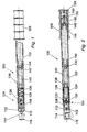
  • Figs. 1 & 2 respectively show a part-sectional elevation, and a sectional plan view of a first embodiment 100 of torque wrench in accordance with the present invention.
  • the torque wrench 100 comprises a longitudinally elongated hollow tubular body 102, a torque limiting/indicating mechanism 104 at the left end of the wrench 100, and a handle 106 at the right end of the wrench 100.
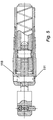
  • the torque limiting/indicating mechanism 104 is shown to an enlarged scale in Fig. 3).
  • the other end of the component 114 is formed as a rotary cam 118 having a camming profile 120 which will subsequently be explained in detail.
  • the socket 116 and the cam 118 are formed integrally, with an intervening hole 122 (see especially Fig. 4) by which the component 114 is rotatably mounted on the pivot pin 110.
  • the right or inboard end of the trunnion 126 (i.e. the end opposite the bearing 132) is formed as a reduced-diameter spigot 138 for mounting one end of a spacer tube 140.
  • the other (right) end of the spacer tube 140 is fitted with a combined slide support and spring seating 142 which serves both to provide seating for the left end of a coiled compression spring 144, and sliding support against the bore of the wrench body 102 for the tube 140 and the spring 144.
  • the right end of the spring 144 seats on a further slide support 146 whose position along the bore of the tubular wrench body 102 is determined by a screw-threaded adjustment member 148.

Landscapes

  • Engineering & Computer Science (AREA)
  • Mechanical Engineering (AREA)
  • Details Of Spanners, Wrenches, And Screw Drivers And Accessories (AREA)

Abstract

A torque wrench of the type that "break" upon achieving a pre-selected maximum. The mechanism used to limit torque is adapted such that excessive wear is avoided and torque preselection remains within acceptable tolerances. This is achieved by providing a roller cam-follower to contact the surface of a cam-like surface mitigating any wear of the surface and/or the cam follower. The wrench is also adapted so that the break in applied torque, which characterises such wrenches, is readily apparent to the user of the wrench by an appreciable change in the alignment between the wrench body and the component engaging section. <IMAGE>

Description

This invention relates to torque wrenches, and relates more particularly but not exclusively to improvements in torque wrenches having means for indicating the achievement of a preselected maximum torque applied in use of the wrench and/or having means for controllably adjusting a preselected maximum torque to be applied by the torque wrench in use thereof.
In the field of hand tools for the controlled manual application of torque to a component (which may, for example, be a fastener), torque wrenches are known forms of torque-applying tool having torque-limiting means for inhibiting or preventing the application through the tool of torque exceeding some predetermined maximum torque; for increased utility, such predetermined maximum torque may be adjustable.
Normal manual operation of a torque wrench incorporating torque-limiting means usually involves the wrench presenting a perceptibly increasing resistance to movement as applied torque increases, up to the preselected maximum torque at which there is a a readily perceptible discontinuity in resistance to movement, commonly in the form of a sharp drop in resistance to movement or "break" in the stiffness of the torque wrench. Resetting of the torque wrench may require a reverse movement of the wrench handle, and/or an increment of forward movement of the wrench handle (i.e. continuation of handle movement in the previous torque-applying direction of handle movement). Torque wrenches are disclosed in British Patents GB0674352, GB0687446, GB0744597, GB0770611, GB0856136, CB1249590, and in published European Patent Application EP0671243-A1.
Where a torque wrench has a predetermined maximum torque that is determined by a spring-loaded roller camming out of a notch formed in a component for transmitting torque to a tool or other torque-receiving article (such a component being, for example, a peripherally notched wheel as described in EP0671243-A1, or an end-notched pivotal coupling component as is used in the Applicants' "TBN 110 Torque Handle"), it has been found that the edges of the notches are susceptible to wear after the torque wrench has been operated many times. This wear of the notch edges changes the operative geometry of maximum-torque-determining mechanism which has the undesirable effect of maladjusting the set torque at which the wrench breaks. While compensatory resetting of the wrench could theoretically keep such maladjustments to a minimal level, if the torque wrench is operated predominantly in one direction (e.g. if the wrench is used mainly for tightening right-hand-threaded fasteners), then wear on opposite edges of the (or each) notch becomes unequal to a significant extent, and the breaking torque becomes unequal in opposite breaking directions (i.e, the clockwise breaking torque becomes unequal to the anticlockwise breaking torque, no matter what the torque setting may be).
According to a first aspect of the present invention there is provided a torque wrench having a mechanism to control maximum torque located between the input and output means of the torque wrench characterised in that said mechanism comprises a cam follower biased into contact with a cam surface through a rolling contact element.
Preferably the output means is rocatable about an axis and the angular extent of rotation of the output means is limited by abutment with another part of the torque wrench.
Preferably the cam surface is located on the output means, and said axis is disposed between the cam surface and a part of the output means for engaging a component which torque is to be applied to.
Preferably the maximum torque is controlled by breaking in one direction only.
Embodiments of the invention will now be described by way of example, with reference to the accompanying drawings wherein: -
  • Fig. 1 is a part-sectional elevation of a first embodiment of torque wrench in accordance with the present invention;
  • Fig. 2 is a sectional plan view of the first embodiment;
  • Fig. 3 is a fragmentary plan view, to a much-enlarged scale, of the left end of the first embodiment;
  • Fig. 4 is a plan view, to a very much enlarged scale, of a combined cam and coupling component comprised in the first embodiment; and
  • Fig. 5 is a sectional elevation of an alternative design for the pivot pin.
  • Referring first to Figs. 1 & 2, these respectively show a part-sectional elevation, and a sectional plan view of a first embodiment 100 of torque wrench in accordance with the present invention. The torque wrench 100 comprises a longitudinally elongated hollow tubular body 102, a torque limiting/indicating mechanism 104 at the left end of the wrench 100, and a handle 106 at the right end of the wrench 100. (The torque limiting/indicating mechanism 104 is shown to an enlarged scale in Fig. 3).
    At the extreme left end of the handle 102 (as viewed in Figs. 1 & 2) is a concentrically fitted hollow tubular end member 108 through which a vertical pivot pin 110 is secured. The pin 110 is retained by a circumscribing resilient ring 112.
    In an alternative embodiment, the pin 110 is eccentric and is retained within an eccentric bore. The pin 110 is held in place by a standard circlip 111 (see Fig. 5)
    A combined tool coupling and cam component 114 is pivotally mounted on the pin 110 for angularly limited movement in the plane of Fig. 2, as will subsequently be detailed. (The combined coupling/cam component 114 is shown separately and to a much-enlarged scale in Fig. 4). The component 114 comprises an end-directed socket 116 having a transversely rectangular cross-section for insertion of a fastener-coupling tool (not shown) that allows torque to be applied to a fastener or other workpiece (not shown). The socket 116 is of a form known per se, and may be substituted by any other suitable form of coupling without affecting the principles of the invention. The other end of the component 114 is formed as a rotary cam 118 having a camming profile 120 which will subsequently be explained in detail. The socket 116 and the cam 118 are formed integrally, with an intervening hole 122 (see especially Fig. 4) by which the component 114 is rotatably mounted on the pivot pin 110.
    Within the hollow tubular end member 108 a slotted bronze bush 124 is fitted. Within the bush 124 a trunnion 126 is slidably mounted for movement in a limited range within the bush 124, sliding movement of the trunnion 126 being along an axis coaxial with the longitudinal axis of the wrench body 102. Sliding movement of the trunnion 126 within the bush 124 is facilitated by a spiral lubricating slot 128 (Fig. 1) formed around the periphery of the trunnion 126.
    The left end of the trunnion 126 (as viewed in Figs. 1-3) is bifurcate to be a sliding fit over the opposite planar faces of the cam 118 (as is most clearly shown in Fig. 1). Between the opposite faces of the bifurcate end of the trunnion 126, to the right of the cam 118, extends a mounting pin 130 which is surface-ground to serve as the inner race of a needle roller bearing 132. The outer race 134 of the bearing 132 is radially thickened for extra strength and rigidity to serve as a wheel by which the bearing 132 rolls over the camming profile 120. (As an alternative to a radially thick outer race, a rolling element bearing with a conventional outer race could be suitably adapted by circumfitting its outer race with a wheel or strong tyre, of steel or of any other suitable material.) Between the mounting pin or inner race 130 and the outer race 134 is a full complement of uncaged needle rollers 136. The bearing 132 is therefore a "cam follower" rolling element bearing which reduces sliding wear between the cam follower and the camming profile. The outer race 134 is resiliently urged against the camming profile 120 by spring means which will now be described in detail.
    Reverting to Figs. 1 & 2, the right or inboard end of the trunnion 126 (i.e. the end opposite the bearing 132) is formed as a reduced-diameter spigot 138 for mounting one end of a spacer tube 140. The other (right) end of the spacer tube 140 is fitted with a combined slide support and spring seating 142 which serves both to provide seating for the left end of a coiled compression spring 144, and sliding support against the bore of the wrench body 102 for the tube 140 and the spring 144. The right end of the spring 144 seats on a further slide support 146 whose position along the bore of the tubular wrench body 102 is determined by a screw-threaded adjustment member 148. By rotating the adjustment member 148 one way or another along its screw-threaded mounting in the bore of the wrench body 102, the member 148 can have its longitudinal position varied in a controllable manner, which in turn varies the position of the right end of the spring 144. When the outer race 134 of the bearing 132 is fully seated on the camming profile 120, with the cam 118 rotated about the pivot pin 110 to its normal position as shown in full lines in Fig. 2, the preset position of the right end of the spring 144 determines the effective length of the spring 144 and hence the spring force exerted through the bearing 132 onto the camming profile 120. As will be further detailed below, the breaking torque of the torque wrench 100 is thereby set. (Once the position of the adjustment member 148 is set to provide a desired level of breaking torque, the member 148 is locked against further movement by a lock 150 attached to the member 148 by a screw 152, and the end of the wrench 100 is sealed by a removable end cap 154. If future adjustment of the breaking torque is required, the end cap 154 is temporarily removed, the member 148 is unlocked, turned as appropriate, and then relocked, followed by recapping of the wrench end.)
    Operation of the torque indicating/limiting mechanism 104 will now be described in detail. The zero-torque configuration of the mechanism 104 is shown in full lines in Fig. 3, in which configuration the wheel or outer race 134 of the bearing 132 will be seated in the minimum-displacement region 120A of the camming profile 120 (Fig. 4). As increasing torque is applied through the wrench 100, the component 114 will start to rotate anticlockwise with respect to the zero-torque configuration (or, to be more precise and assuming the fastener or other workpiece acted upon by the wrench 100 to be unmoving, the wrench body 102 will start to rotate clockwise about the pivot pin 110 with respect to the component 114 of which the cam 118 is an integral part), and consequently the outer race 134 will ride up the camming profile 120 to the region denoted 120B in Fig. 4. In this position, the centre of the bearing 132 will be further from the cam pivot 110, and consequently the spring 144 will be more compressed than in the zero-torque configuration. This manifests both as applied (non-zero) torque and as a corresponding back-resistance to continued movement of the handle 106. Further increasing the applied torque will cause the outer race 134 to ride further up the camming profile 120, eventually to reach the point denoted 120C, at which point the radial separation of the camming profile 120 from the rotational centre of the cam 118 (i.e. the axis of the pivot pin 110) is near its maximum. Rotationally beyond the point 120c, the camming profile 120 "levels out" to a region 120D in which the cam radius increases relatively little; this provides a dead-band in which torque cannot further increase by any significant amount but the angular displacement between the component 114 and the body 102 increases noticeably, i.e. the wrench 100 has undergone a "break" which is easily detected by the wrench operator by reason of the relatively high twenty-degree rotation.
    It is particularly advantageous that the transition of the camming profile 120 between the maximum torque point 120C and the dead-band region 120D is free of discontinuities, i.e. there is no abrupt change of slope in the camming profile such as is normal in prior art torque wrenches which depend upon a member being forced out of a sharp-edged notch (see, for example, Figs. 2 & 34 of EP0671243-A1). The absence of discontinuities from the camming profile of the present invention obviates or minimises stress concentrations at break, which would otherwise lead to excessive wear of the camming profile just at its torque-determining point, and hence to rapid maladjustment of breaking torque. A further significant advantage of the present invention is that the camming profile is much larger than the equivalent profile in prior art torque wrenches having multiple break points distributed around a cam and occupying a comparable internal volume within the wrench, such that camming loads become distributed over inherently larger areas with consequent further reductions of stress and stress-induced wear. A still further advantage of the present invention is that the camming profile presents a single break point, i.e. unlike the prior art torque wrench cams wherein the notches could be broken out of in either rotational direction, the mechanism 104 works in one rotational direction only, such that it is fundamentally impossible to cause unequal wear of plural break-point-setting cam profile regions (and consequent asymmetry of break torques).
    Attempting to increase the applied torque beyond the set torque at break (at which time the operator would normally relax manual force because desired torque had been achieved and so indicated by the breaking of the wrench) will cause contact point between the race 134 and the camming profile 120 to move away from the break point 120C and across the region 120D until the cam edge 156 abuts the inside of the end member 108, as depicted in dashed lines in Fig. 2. The impact of this abutment will give further notice to the operator to discontinue the application of torque; alternatively, the operator may then knowingly apply greater torque if desired, as the limiting effect of the cam arrangement is bypassed.
    While certain modifications and variations have been described above, the invention is not restricted thereto and other modifications and variations can be adopted without departing from the scope of the invention.

    Claims (4)

    1. A torque wrench having a mechanism to control maximum torque located between the input and output means of the torque wrench characterised in that said mechanism comprises a cam follower biased into contact with a cam surface through a rolling contact element.
    2. A torque wrench according to claim 1 in which the output means is rotatable about an axis and the angular extent of rotation of the output means is limited by abutment with another part of the torque wrench.
    3. A torque wrench according to claim 2 in which the cam surface is located on the output means, and said axis is disposed between the cam surface and a part of the output means for engaging a component which torque is to be applied to.
    4. A torque wrench according to any preceding claim wherein the maximum torque is controlled by breaking in one direction only.
    EP01301942A 2000-03-03 2001-03-02 Torque wrenches Withdrawn EP1147858A3 (en)

    Applications Claiming Priority (2)

    Application Number Priority Date Filing Date Title
    GB0005213A GB0005213D0 (en) 2000-03-03 2000-03-03 Torque wrenches
    GB0005213 2000-03-03

    Publications (2)

    Publication Number Publication Date
    EP1147858A2 true EP1147858A2 (en) 2001-10-24
    EP1147858A3 EP1147858A3 (en) 2002-06-05

    Family

    ID=9886951

    Family Applications (1)

    Application Number Title Priority Date Filing Date
    EP01301942A Withdrawn EP1147858A3 (en) 2000-03-03 2001-03-02 Torque wrenches

    Country Status (2)

    Country Link
    EP (1) EP1147858A3 (en)
    GB (1) GB0005213D0 (en)

    Cited By (3)

    * Cited by examiner, † Cited by third party
    Publication number Priority date Publication date Assignee Title
    WO2014188256A1 (en) * 2013-05-22 2014-11-27 Sam Outillage Click mechanism for a torque wrench allowing a large break angle
    WO2019138401A1 (en) 2018-01-14 2019-07-18 MIS Implants Technologies Ltd. Dental torque wrench
    TWI714442B (en) * 2020-01-20 2020-12-21 和嘉興精密股份有限公司 Torsion structure

    Family Cites Families (5)

    * Cited by examiner, † Cited by third party
    Publication number Priority date Publication date Assignee Title
    US2959078A (en) * 1959-06-17 1960-11-08 Skidmore Hungerford Ind Inc Predetermined torque release wrench
    US3140623A (en) * 1961-08-29 1964-07-14 Pendleton Tool Ind Inc Predetermined torque release wrench
    US4316397A (en) * 1980-07-03 1982-02-23 Skidmore Engineering Div. Buckeye Gear Company Torque wrench
    US4870879A (en) * 1988-07-05 1989-10-03 James Shieh Quick-set dial type torque wrench
    DE19615241C1 (en) * 1996-04-18 1998-02-12 Aesculap Ag & Co Kg Surgical torque wrench

    Cited By (4)

    * Cited by examiner, † Cited by third party
    Publication number Priority date Publication date Assignee Title
    WO2014188256A1 (en) * 2013-05-22 2014-11-27 Sam Outillage Click mechanism for a torque wrench allowing a large break angle
    FR3005884A1 (en) * 2013-05-22 2014-11-28 Sam Outil RESTRICTIVE MECHANISM FOR A HIGH CASSURE DYNAMOMETRIC KEY, COMPRISING A CAM-SENSOR ASSEMBLY AND FORK-HOLDER PIVOT DEPARTURE IN FRONT OF THE BODY OF THE KEY
    WO2019138401A1 (en) 2018-01-14 2019-07-18 MIS Implants Technologies Ltd. Dental torque wrench
    TWI714442B (en) * 2020-01-20 2020-12-21 和嘉興精密股份有限公司 Torsion structure

    Also Published As

    Publication number Publication date
    EP1147858A3 (en) 2002-06-05
    GB0005213D0 (en) 2000-04-26

    Similar Documents

    Publication Publication Date Title
    CA1281538C (en) Keyless chuck and method therefor
    US4938094A (en) Device for effecting the fine adjustment of the angular orientation of a steering-wheel on a motor vehicle steering-wheel shaft
    EP0696525B1 (en) Rotary recliner
    US4530262A (en) Releasably lockable articulated handle
    US7185896B2 (en) Chuck with locking system
    US6948410B1 (en) Torque wrench with sleeve for locking rotatable handle
    US20020113445A1 (en) Clutch handle
    AU2231395A (en) Indexable wrenches
    FR2557992A1 (en) DEVICE FOR ADJUSTING THE ANGULAR POSITION OF A ROTATING BODY WITH A SHAFT, IN PARTICULAR A STEERING WHEEL OF A MOTOR VEHICLE ASSOCIATED WITH A STEERING COLUMN.
    US5775184A (en) Indexable wrenches
    US7044036B1 (en) Preset torque wrench with multiple setting torque selector mechanism
    DE10033666A1 (en) Adjustment fitting especially for inclination adjustment of seat back in motor vehicle has wedge sections of eccentric lying one above other in radial direction and increase in thickness in opposite directions
    JPH071354A (en) Method of adjusting driver, wrench main body and joint
    EP0658472B1 (en) Quick release apparatus for a bicycle
    DE69611910T2 (en) LEVER OPERATED LINING WITHOUT KEY
    EP1147858A2 (en) Torque wrenches
    US3270594A (en) Predetermined torque release wrench
    DE19606795A1 (en) Drill chuck
    EP1131214B1 (en) Wheel suspension, especially for nonpowered vehicle axles
    US8100617B2 (en) Fastener system with frangible member
    CA2109177C (en) Stud driver and remover for large diameter studs
    DE60102977T2 (en) Tool for mounting and removing tires on and from wheel rims
    EP0572771A1 (en) Articulation comprising cantilever parts connected via an articulated axle
    US4475744A (en) Telescoping steering shaft with adjusted lash
    DE10031979C1 (en) One-way driving control mechanism for wrench, has spinner stored in housing at wrench head and has elliptical cylindrical middle part encircled by diameter variable grommet

    Legal Events

    Date Code Title Description
    PUAI Public reference made under article 153(3) epc to a published international application that has entered the european phase

    Free format text: ORIGINAL CODE: 0009012

    AK Designated contracting states

    Kind code of ref document: A2

    Designated state(s): AT BE CH CY DE DK ES FI FR GB GR IE IT LI LU MC NL PT SE TR

    AX Request for extension of the european patent

    Free format text: AL;LT;LV;MK;RO;SI

    PUAL Search report despatched

    Free format text: ORIGINAL CODE: 0009013

    AK Designated contracting states

    Kind code of ref document: A3

    Designated state(s): AT BE CH CY DE DK ES FI FR GB GR IE IT LI LU MC NL PT SE TR

    AX Request for extension of the european patent

    Free format text: AL;LT;LV;MK;RO;SI

    AKX Designation fees paid

    Designated state(s): AT BE CH CY DE DK ES FI FR GB GR IE IT LI LU MC NL PT SE TR

    STAA Information on the status of an ep patent application or granted ep patent

    Free format text: STATUS: THE APPLICATION IS DEEMED TO BE WITHDRAWN

    18D Application deemed to be withdrawn

    Effective date: 20021206