EP1147747A2 - Dental capsule for placement of ultra-high viscosity dental composite material - Google Patents
Dental capsule for placement of ultra-high viscosity dental composite material Download PDFInfo
- Publication number
- EP1147747A2 EP1147747A2 EP01108941A EP01108941A EP1147747A2 EP 1147747 A2 EP1147747 A2 EP 1147747A2 EP 01108941 A EP01108941 A EP 01108941A EP 01108941 A EP01108941 A EP 01108941A EP 1147747 A2 EP1147747 A2 EP 1147747A2
- Authority
- EP
- European Patent Office
- Prior art keywords
- piston
- capsule
- body portion
- dental
- passageway
- Prior art date
- Legal status (The legal status is an assumption and is not a legal conclusion. Google has not performed a legal analysis and makes no representation as to the accuracy of the status listed.)
- Withdrawn
Links
Images


Classifications
-
- A—HUMAN NECESSITIES
- A61—MEDICAL OR VETERINARY SCIENCE; HYGIENE
- A61C—DENTISTRY; APPARATUS OR METHODS FOR ORAL OR DENTAL HYGIENE
- A61C5/00—Filling or capping teeth
- A61C5/60—Devices specially adapted for pressing or mixing capping or filling materials, e.g. amalgam presses
- A61C5/66—Capsules for filling material
Definitions
- This invention is directed generally to a dental capsule for the direct placement of composite type restorative dental material, and more specifically to a unit dose dental capsule for the direct placement of ultra-high density, i.e. packable or condensable composite or heavy viscosity materials to a prepared tooth by syringing.
- ultra-high density i.e. packable or condensable composite or heavy viscosity materials
- Dental composite material for restoring teeth was first introduced into dentistry about the mid 1960's.
- the initial composites had a paste-like consistency.
- dentists encountered considerable difficulty in the placement of such composite material into a prepared tooth.
- the dentist would apply such paste-like composite resin material to a tooth by means of a spatula, palate or like tool.
- This manual technique resulted in the tooth being filled from the outside in.
- this spatula technique of placing such composite resulted in the formation of voids within the finished restoration. This was because the spatula or palate technique of placing such material in a tooth could not satisfactorily pack the paste composite material into the small and difficult to reach areas of the tooth.
- these known capsules are provided with a reservoir portion for containing a predetermined supply of dental material having an internal diameter which is substantially greater than the internal diameter of the discharge orifice.
- These known capsule constructions have been designed to handle and be used with the then available composites having a paste-like consistency, i.e., a composite resin composition having a filler content of 78% by weight or less. The lower the filler content, the less viscous the material, and the more readily it can be syringed through the relatively small discharge orifice of the known capsule designs.
- the composite dental materials are being formulated with a substantially larger filler content, i.e., more than 78% filled whereby such highly filled or ultra dense composites are rendered "packable” or “condensable” to imitate amalgam in consistency.
- ultra dense or condensable composite materials are particularly suitable for restoring the back or posterior teeth.
- the particular condensable properties of such ultra dense composite materials makes it difficult to dispense from bulk syringes.
- the extreme viscous properties of such ultra dense dental composites have also prohibited the placement of such ultra dense composite material by the use of the syringing technique utilizing the known capsule constructions, which the dental profession has virtually universally adopted as the preferred method of delivering a composite material directly into a prepared cavity.
- An object of this invention is to provide a capsule construction particularly suitable for effecting the placement of ultra dense or highly filled composite resin dental restorative materials by means of the syringing technique.
- Another object is to provide a capsule construction for dispensing an ultra dense or packable composite resin material directly to a tooth in a manner to minimize any formation of voids.
- Another object is to provide a capsule and plug arrangement which is particularly suitable for packaging and dispensing an ultra dense compactable composite resin material.
- Another object is to provide a capsule and plug arrangement constructed so as to insure that the entire amount of material contained in the capsule is completely discharged or ejected from the capsules so as to completely eliminate any waste.
- a capsule construction having a generally cylindrical shaped body portion defining a reservoir for receiving a predetermined amount of ultra dense dental composite resin material.
- the body portion is provided with a full opening at one end with the other end thereof terminating in a nozzle having a discharge orifice disposed at an angle relative to the central longitudinal axis of the body portion.
- the body portion defining the reservoir is provided with an internal diameter which is equal to or only slightly larger than the internal diameter of the nozzle or discharge orifice.
- the internal surface or bore of the body portion is uniform and smooth throughout and is connected in communication with the passageway of the nozzle so as to be free of any obstruction to provide for a smooth transition therebetween.
- the ratio between the internal diameter of the nozzle discharge orifice or opening (d) relative to the internal diameter of the body portion (D) preferably ranges between 1 to 1 to .60 to 1.
- the open end of the body portion is sealed by a displaceable piston or plug which may be spherical, cylindrical or rod-like and/or a combination thereof so as to be rendered bi-directional. Adjacent the open end, the internal surface of the body portion is provided with one or more longitudinally extending venting grooves to facilitate the venting of any entrapped air upon the insertion of the displaceable piston.
- a laterally extending collar or flange circumscribes the open end of the body portion and a sealing member is fitted to the nozzle for sealing the discharge orifice.
- the displaceable piston comprises a flexible elongated rod which is generally uniform in cross-section so as to be snugly received in the open end of the capsule to seal the material therein which, when displaced, can readily flex about the transition area and slide through the bore of the nozzle to eject all the material from the bore of the nozzle.
- Fig. 1 is a top plan view of a dental capsule embodying the invention.
- Fig. 2 is a sectional view taken on line 2-2 of Fig. 1.
- Fig. 3 is a side view of the capsule of Fig. 1 with a sealing cap and having portions broken away.
- Fig. 4 is a detail perspective view of the sealing cap.
- Fig. 5 is a front end view of the capsule of Fig. 1 with the sealing cap removed.
- Fig. 6 is a rear or left end view of Fig. 2.
- Fig. 7 is a perspective view of a piston for use with the capsule of Fig. 1.
- Fig. 8 is a perspective view of a modified piston construction.
- Fig. 9 is a perspective view of another modified piston construction.
- Fig. 10 is a perspective view of another modified piston construction.
- Fig. 11 is a modified form of the invention.
- Fig. 12 is a perspective view of another modified embodiment.
- Fig. 13 is a perspective view of still another embodiment.
- Fig. 14 is a perspective view of still another embodiment.
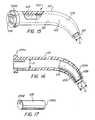
- Fig. 15 is a perspective view of a modified form of the invention having parts broken away.
- Fig. 16 is a sectional view of Fig. 15 illustrating the piston in the fully extruded position.
- Fig. 17 is a detail side view of the piston of Figs. 15 and 16.
- the dental capsule 20 is specially constructed for use with ultra high density dental composite restorative material.
- Ultra high density dental composite material as used herein is defined as a dental composite restorative resin material having in excess of 78% by weight of a filler material which may comprise barium, aluminum silicate, fumed silica, glass, quartz or other inorganic fillers commonly used by the makers of composite resin dental material.
- Composite resin material having a filler content in excess of 78% renders the composition "condensable” or "packable” to simulate amalgam, which renders such ultra highly dense composites suitable for restoring the molars or back teeth.
- such ultra dense composites could not be placed by utilizing the preferred syringing technique, which is now widely accepted as the preferred method of placing composites in effecting a tooth restoration.
- the capsule construction 20 is provided with a cylindrical body portion 21 having an internal bore 22 defining a reservoir 23 for containing a predetermined amount of ultra dense composite material M.
- One end of the capsule body portion 21 is provided with a full open end 24 which is sealed or closed by a displaceable piston 25, as will be herein described.
- the bore 22 is of a generally uniform diameter throughout the length of the body portion 21.
- the passageway 28 formed in the nozzle and terminating at the discharge orifice 27 also has a generally constant diameter throughout the length thereof.
- a slight transition zone 29 At the bend defined by the intersection of the axis of the nozzle passageway 28 and the axis of the body portion, there is formed a slight transition zone 29.
- the arrangement is such that the internal walls defining the nozzle passageway 28, the bore 22 of the capsule body 21, and the transition zone 29 therebetween are free of any obstruction so as to permit the uninterrupted flow of the ultra dense material therethrough with a minimum of any resistive forces acting thereon during the extrusion of the ultra dense material M.
- the optimal ratio of the internal diameter "D" of the bore 22 relative to that of the internal diameter "d” of the passageway 28 is 1 to 1 or approximately 1 to 1.
- this ratio may vary slightly.
- the ratio of relative diameters, i.e. d / D of this example is .83, which is slightly less than the optimal ratio of 1 to 1.
- the lower ratio permits a slight reduction of the internal diameter of the nozzle discharge passageway 28 relative to that of the internal bore 22 to accommodate the placement of the material into a smaller prepared cavity of the tooth to be restored by the syringing technique.
- An optimum ratio of said diameters d / D may range between .60 to 1.
- the ultra dense material M placed in capsule 20 can be readily extruded by placing the capsule in any of the known syringe guns, e.g. such as disclosed in U.S. Patent 4,198,756 and those subsequently patented which embody the mechanical advantage of U.S. Patent 4,198,756.
- venting grooves 30 may be formed in the internal wall of the body portion 21 adjacent the open end 24. As shown, the venting grooves 30 define a vent means through which any air entrapped within the capsule may be displaced when the piston 25 is inserted to seal the material M therein. With the piston 25 in place, the piston effectively seals off the vent grooves 30 to the outside atmosphere.
- Piston 25 is provided with a cylindrical portion 25A having a diameter sized so as to be frictionally received within the bore 22 of the capsule body.
- the leading end 25B of the piston is curvilinear to complement the slight curvature of the transition zone 29 so that a maximum amount of the material within the reservoir 23 may be extruded.
- the mouth 31 of opening 24 diverges slightly outwardly, as indicated, to facilitate the insertion of piston 25. It will thus be apparent that as the piston 25 is displaced by the force of the syringe plunger acting on the piston as disclosed in U.S. Patent 4,198,756, the dense material M is expressed as a "rod" through the discharge orifice 27, with a minimum of resistance, other than sliding resistance.
- a sealing cap 32 is provided to seal the discharge orifice to prevent any contamination of the material within the capsule and/or to prevent any light from penetrating, in the event the material M is light activated.
- the sealing cap 32 is provided with a cup shaped body 33 sized to be frictionally retained on the discharge nozzle 26. Circumscribing the opening of the sealing cap 32 is a laterally extending circumscribing flange 34.
- the capsule is fabricated of a material that is opaque to the actinic light of the dental material as more particularly set forth in U.S. Patent 5,122,057, which is incorporated herein by reference.
- the capsule 20 may also be provided with a laterally extending flange or collar 35 which circumscribes the open end 24.
- the internal walls or surfaces of the capsule may be lightly coated or lubricated with a material that does not interfere with the chemistry of the composite material.
- the coating material should comprise a component of the composite composition itself.
- the composite material includes as a part thereof a liquid monomer, said liquid monomer may be used to lubricate the internal surfaces of the capsule without adversely effecting the chemistry of the composition.
- the lubricant may also comprise a silicone or Teflon, which may be applied to the inner surfaces of the capsule or be added to the material out of which the capsules may be molded, in which case the lubricating material is integrally molded in the capsule.
- Figs. 8, 9 and 10 illustrate other alternative piston construction which may be utilized in the capsule 20 described.
- the piston 36 of Fig. 8 comprises a cylindrical body having opposed flat or blunt ends 37, 38.
- the piston 36 has the advantage of ease of manufacture as the piston 36 can be readily fabricated by forming a rod and thereafter severing such rod into several parts to form the piston 36. Thus, a mold is not essential in forming a piston 36.
- Fig. 9 illustrates another modified piston construction.
- Piston 40 of Fig. 9 includes a central cylindrical body portion 41 having similar or identical spheroidal end portions 42, 43. It will be understood that the opposed end portions 42, 43 may be hemispherical, ellipsoidal or other curvilinear or arcuate shape.
- the advantage of piston 40 is that it is immaterial which end of the piston 40 is first inserted into the open end of the capsule.
- the piston construction of Figs. 8 and 9 are bi-directional which is important during the assembly and/or filling of the described capsule.
- Fig. 10 illustrates a piston 50 which is formed in the shape of a sphere. It will be understood that the diameter of the sphere shaped piston 50 is such that the outer surface of the sphere piston 50 is disposed in sealing relationship to the internal walls of the capsule body, as seen in Fig. 11.
- the spherical piston 50 has the advantage that when used, it defines a line contact seal with the internal walls of the capsule and minimizes any sliding friction between the piston 50 and the internal walls of the capsule. Also, the piston 50 eliminates any need to orient the piston 50 relative to the capsule during assembly.
- Fig. 11 illustrates a modified form of the invention.
- the capsule construction 60 is identical to that described with respect to Figs. 1 to 3.
- the nozzle of the capsule 60 is sealed by an end plug 61.
- the end plug has a stem 62 sized to seal the passageway 63 formed in the nozzle 64 of capsule 60.
- a flange 65 Connected to the stem 62 is a flange 65 which functions as a stop to limit the insertion distance of the stem 62.
- the piston 66 shown in Fig. 11 comprises a spherical piston, hereinbefore described with respect to Fig. 10.
- the construction and functioning of capsule 60 is similar to that described with respect to capsule 20 of Figs. 1 and 2.
- Fig. 12 is a perspective view of a further modification of the invention.
- the capsule 70 has a curvilinear body 71 of a predetermined radius R to define a smooth uninterrupted passageway extending from the open end 72 of the capsule 70 to the discharge orifice 73.
- the passageway or bore 74 has a uniform diameter throughout the length of the body 71.
- the orifice 73 is sized so as to minimize any resistant forces during extrusion of the ultra dense composite material.
- the spherical piston 50 would be ideal for extruding the material through the nozzle orifice 73.
- a laterally extending flange or collar 75 circumscribes the opened end 72.
- Capsule 70 may also be provided with one or more venting grooves 76 of the type hereinbefore described with respect to the embodiment of Fig. 2.
- discharge orifice 73 of capsule 70 may be sealed either by a sealing cap 32 or end plug 61 as previously described with respect to Figs. 3 and 10.
- the bore of the capsule body 71 is of uniform or constant diameter D from the open end 72 to the discharge orifice 73 so as to have the optimum ratio of 1 to 1 as hereinbefore described.
- capsule 70 In all other respects, the operation or functioning of capsule 70 is similar to that hereinbefore described.
- Fig. 13 illustrates another slightly modified embodiment.
- the capsule 80 is virtually similar to that of Figs. 1 to 3 with the exception that the internal diameter D of the capsule cylindrical body portion 81 is equal to diameter D' of the nozzle passageway 82, which terminates at the discharge orifice 83.
- the nozzle portion 84 is angularly disposed similar to that described with respect to Figs. 1 to 3.
- the capsule 80 is similar in structure and function to that described with respect to Figs. 1 to 3.
- Fig. 14 illustrates yet another embodiment.
- the capsule 90 has a body portion 91 which defines the reservoir for containing a predetermined amount of the ultra-high density or viscous material.
- Capsule 90 is provided with a bore having a uniform or constant diameter D therethrough and is open at one end 92. The other end 93 is closed by a sloping or curvilinear end wall 94.
- the discharge orifice 95 is disposed in the wall portion of the capsule body adjacent the end wall 94.
- Circumscribing the open end 92 is a lateral extending circumscribing flange 96. It will be understood that any of the pistons hereinbefore described may be used to seal the ultra high viscosity material within the capsule 90.
- the discharge orifice 95 is formed with a diameter " d " which may be equal to or slightly less than diameter "D" of the bore of capsule 90 so as to define a ratio of "d" / "D” ranging between .60 to 1.
- capsule 90 To seal the discharge orifice 95, capsule 90 is provided with a sealing cap 97 which is frictionally fitted to the closed end 93 of the capsule 90 with sufficient depth to seal the orifice 95.
- the open end of the seal cap 97 is provided with an outwardly extending flange 98, which provides an edge to facilitate the placement of the sealing cap 97 onto and off the closed end 93 of the capsule 90.
- the construction and operation of capsule 90 is similar to that hereinbefore described.
- Fig. 15 illustrates another modified embodiment of this invention.
- the capsule 100 comprises a body portion 101 having an internal bore 102 defining a reservoir 103 for receiving a predetermined amount of dental material as hereinbefore described.
- the internal diameter "D" is equal to or only slightly greater than the internal diameter "d" of the discharge orifice opening 107.
- the walls 107A defining the discharge nozzle 106 are made thinner than the thickness of the walls defining the body 101 or reservoir portion of the capsule 100.
- the outer surface of the nozzle may taper inwardly slightly in the direction of the discharge orifice 107. This slight thinning of the walls defining the nozzle 106 imparts a slight flexibility to the walls of the discharge end at the nozzle 106.
- the end of the body portion 101 opposite the discharge nozzle 106 is fully opened as hereinbefore described for receiving the dental material, and which opening 104 is sealed by a displaceable piston 105.
- the piston comprises an elongated rod formed of a suitable flexible material that is sufficiently rigid to effect the extrusion of the material when the piston 105 is displaced, yet flexible enough to negotiate the transition area 109 between the reservoir portion and the connected nozzle 106.
- the outside diameter of the displaceable piston 105 forms a snug fit with the internal diameter "D" of the capsule body portion 101 to form a seal thereat, and yet is rendered freely slideable when displaced to extrude the dental material.
- the piston 105 be formed of a Teflon material as such material is self lubricating, and will freely slide while maintaining a positive seal with the internal surface of the reservoir, and is sufficiently flexible to negotiate the smooth transition area 109, as seen in Fig. 16.
- rod shaped piston 105 is rendered bi-directional in that it is immaterial which end is inserted into the capsule body to seal the material therein.
- the opposed ends 105A, 105B of the piston 105 are blunt or flat.
- the same bi-directional result may be achieved if the opposed ends 105A, 105B were made curvilinear, e.g. hemispherical or conical.
- a circumscribing flange 104A circumscribes the open end 104 as previously described.
- the piston 105 is sufficiently long so as to insure that all of the material within the bore or passageway of the nozzle is extruded.
- the piston is formed of a suitable material, e.g. Teflon, that is sufficiently flexible to negotiate the gentle curve in the transition zone 109, and sufficiently compressible for passage through the bore or passage of the nozzle in the event the internal diameter "d" of the orifice or discharge opening is less than "D" or equal to or greater than "d".
- the walls of the nozzle may be tapered as hereinbefore described so as to render the walls of the nozzle sufficiently flexible so as to permit the piston 105 to slide therethrough as noted in Fig. 15.
- Figs. 15 to 17 the construction of the embodiment of Figs. 15 to 17 is similar to that hereinbefore described, e.g. the capsule of Figs. 15 and 16 may have its discharge nozzle sealed by an end cap as hereinbefore described and provided with vent means, also as described.
- the capsule of Figs. 15 and 16 is particularly suitable for dispensing and placing ultra-dense or compactable composite material. As such materials are relatively expensive, the elimination of any possible waste is an important aspect of this invention.
- the principle common to each of the described embodiments for rendering ultra dense, compactable or condensable material syringeable so as to prohibit the formation of voids is that the internal diameter "d" of the passageway of the nozzle and/or discharge orifice of the respective described capsule embodiments be equal to or relatively close to the internal diameter "D" of the capsule body portion with no corners or shaped angles disposed in the transitional area thereinbetween.
- the ultra dense composite material is caused to be displaced as a "slug" in being forced out of the discharge orifice during an extruding operation, with little or no resistance being imparted thereto as it begins sliding.
- Coating the internal surfaces of the described capsule constructions with a thin film of a lubricant compatible with the ultra dense composite material functions to further reduce or minimize any sliding friction occurring between the "slug" of material and the internal walls of the capsule during extrusion.
- a Teflon piston as described with respect to the embodiment of Figs. 15-17 also aids in minimizing sliding friction.
- the capsules described herein are preferably made of a suitable plastic material which is compatible with the composition of the ultra dense composite material dispensed thereby.
- plastic materials may be selected from the group consisting of polypropylene, nylon, delrin, and/or like materials such as previously taught in the dental capsule art herein cited.
- the pistons may also be formed of similar type plastic materials and/or rubber or synthetic rubber or a fluoropolymer, e.g. Teflon, as described with respect to Figs. 15 to 17.
Landscapes
- Health & Medical Sciences (AREA)
- Oral & Maxillofacial Surgery (AREA)
- Dentistry (AREA)
- Epidemiology (AREA)
- Life Sciences & Earth Sciences (AREA)
- Animal Behavior & Ethology (AREA)
- General Health & Medical Sciences (AREA)
- Public Health (AREA)
- Veterinary Medicine (AREA)
- Dental Tools And Instruments Or Auxiliary Dental Instruments (AREA)
Abstract
Description
- This invention is directed generally to a dental capsule for the direct placement of composite type restorative dental material, and more specifically to a unit dose dental capsule for the direct placement of ultra-high density, i.e. packable or condensable composite or heavy viscosity materials to a prepared tooth by syringing.
- Dental composite material for restoring teeth was first introduced into dentistry about the mid 1960's. The initial composites had a paste-like consistency. As a result, dentists encountered considerable difficulty in the placement of such composite material into a prepared tooth. Generally, the dentist would apply such paste-like composite resin material to a tooth by means of a spatula, palate or like tool. This manual technique resulted in the tooth being filled from the outside in. It was noted that this spatula technique of placing such composite resulted in the formation of voids within the finished restoration. This was because the spatula or palate technique of placing such material in a tooth could not satisfactorily pack the paste composite material into the small and difficult to reach areas of the tooth. The placement of such composite material with a palate or spatula also resulted in the entrainment of air and the formation of air bubbles in the composite material as it is being placed. The formation of such voids or air bubbles compromised the strength and durability of the finished restoration. A further difficulty that was encountered by the dentist was that such composite material had a tendency to stick to the palate or spatula, causing the material to be pulled away when the dentist removed the palate or spatula. Also, if a dentist used a metal instrument to place the composite material, there was a tendency of the metallic instrument to react and discolor the composite.
- The problems initially encountered by the dentist in placing such composite resins were solved by the development of the syringing technique for the placement of such composite materials. This syringing technique was first disclosed in U.S. Patent 3,581,399 granted June 1, 1971 to Dr. William B. Dragan. The syringing technique and unit dose capsules disclosed in said U.S. Patent 3,581,399 was followed up by other capsule improvements as disclosed in U.S. Patents 4,963,093; 4,969,816; 5,083,921; 5,129,825; 5,165,890 and 5,172,807. These known capsule constructions proved satisfactory for placing the composite materials having a paste-like consistency and/or a composite material having a filler content of less than 78% by weight.
- Other known capsules from which such paste-like composites could be syringed are disclosed in U.S. Patents 4,330,280; 4,384,853; 4,391,590; 4,767,326; 5,100,320; 5,322,440; 5,460,523 and 5,707,234.
- Generally, these known capsules are provided with a reservoir portion for containing a predetermined supply of dental material having an internal diameter which is substantially greater than the internal diameter of the discharge orifice. These known capsule constructions have been designed to handle and be used with the then available composites having a paste-like consistency, i.e., a composite resin composition having a filler content of 78% by weight or less. The lower the filler content, the less viscous the material, and the more readily it can be syringed through the relatively small discharge orifice of the known capsule designs.
- It has also been observed in the prior known capsule constructions that the arrangement was such that it was never possible to attain total evacuation of the dental material from the capsule so matter how flowable the material. This was because a portion of the material always remained in the nozzle portion of the capsule as the displacement of the plug or piston was limited by the end wall of the capsule. As a result, the portion of the dental material remaining in the nozzle of the capsule was always wasted.
- More recently, the composite dental materials are being formulated with a substantially larger filler content, i.e., more than 78% filled whereby such highly filled or ultra dense composites are rendered "packable" or "condensable" to imitate amalgam in consistency. Such ultra dense or condensable composite materials are particularly suitable for restoring the back or posterior teeth. The particular condensable properties of such ultra dense composite materials makes it difficult to dispense from bulk syringes. The extreme viscous properties of such ultra dense dental composites have also prohibited the placement of such ultra dense composite material by the use of the syringing technique utilizing the known capsule constructions, which the dental profession has virtually universally adopted as the preferred method of delivering a composite material directly into a prepared cavity.
- An object of this invention is to provide a capsule construction particularly suitable for effecting the placement of ultra dense or highly filled composite resin dental restorative materials by means of the syringing technique.
- Another object is to provide a capsule construction for dispensing an ultra dense or packable composite resin material directly to a tooth in a manner to minimize any formation of voids.
- Another object is to provide a capsule and plug arrangement which is particularly suitable for packaging and dispensing an ultra dense compactable composite resin material.
- Another object is to provide a capsule and plug arrangement constructed so as to insure that the entire amount of material contained in the capsule is completely discharged or ejected from the capsules so as to completely eliminate any waste.
- The foregoing objects and other features and advantages are attained by a capsule construction having a generally cylindrical shaped body portion defining a reservoir for receiving a predetermined amount of ultra dense dental composite resin material. The body portion is provided with a full opening at one end with the other end thereof terminating in a nozzle having a discharge orifice disposed at an angle relative to the central longitudinal axis of the body portion. The body portion defining the reservoir is provided with an internal diameter which is equal to or only slightly larger than the internal diameter of the nozzle or discharge orifice. The internal surface or bore of the body portion is uniform and smooth throughout and is connected in communication with the passageway of the nozzle so as to be free of any obstruction to provide for a smooth transition therebetween. The ratio between the internal diameter of the nozzle discharge orifice or opening (d) relative to the internal diameter of the body portion (D) preferably ranges between 1 to 1 to .60 to 1. The open end of the body portion is sealed by a displaceable piston or plug which may be spherical, cylindrical or rod-like and/or a combination thereof so as to be rendered bi-directional. Adjacent the open end, the internal surface of the body portion is provided with one or more longitudinally extending venting grooves to facilitate the venting of any entrapped air upon the insertion of the displaceable piston. A laterally extending collar or flange circumscribes the open end of the body portion and a sealing member is fitted to the nozzle for sealing the discharge orifice. In one form of the invention, the displaceable piston comprises a flexible elongated rod which is generally uniform in cross-section so as to be snugly received in the open end of the capsule to seal the material therein which, when displaced, can readily flex about the transition area and slide through the bore of the nozzle to eject all the material from the bore of the nozzle.
- Fig. 1 is a top plan view of a dental capsule embodying the invention.
- Fig. 2 is a sectional view taken on line 2-2 of Fig. 1.
- Fig. 3 is a side view of the capsule of Fig. 1 with a sealing cap and having portions broken away.
- Fig. 4 is a detail perspective view of the sealing cap.
- Fig. 5 is a front end view of the capsule of Fig. 1 with the sealing cap removed.
- Fig. 6 is a rear or left end view of Fig. 2.
- Fig. 7 is a perspective view of a piston for use with the capsule of Fig. 1.
- Fig. 8 is a perspective view of a modified piston construction.
- Fig. 9 is a perspective view of another modified piston construction.
- Fig. 10 is a perspective view of another modified piston construction.
- Fig. 11 is a modified form of the invention.
- Fig. 12 is a perspective view of another modified embodiment.
- Fig. 13 is a perspective view of still another embodiment.
- Fig. 14 is a perspective view of still another embodiment.
- Fig. 15 is a perspective view of a modified form of the invention having parts broken away.
- Fig. 16 is a sectional view of Fig. 15 illustrating the piston in the fully extruded position.
- Fig. 17 is a detail side view of the piston of Figs. 15 and 16.
- Referring to the drawings, there is illustrated in Figs. 1 to 3 one form of the invention. As shown, the
dental capsule 20 is specially constructed for use with ultra high density dental composite restorative material. Ultra high density dental composite material as used herein is defined as a dental composite restorative resin material having in excess of 78% by weight of a filler material which may comprise barium, aluminum silicate, fumed silica, glass, quartz or other inorganic fillers commonly used by the makers of composite resin dental material. Composite resin material having a filler content in excess of 78% renders the composition "condensable" or "packable" to simulate amalgam, which renders such ultra highly dense composites suitable for restoring the molars or back teeth. Heretofore, such ultra dense composites could not be placed by utilizing the preferred syringing technique, which is now widely accepted as the preferred method of placing composites in effecting a tooth restoration. - In order to render such ultra dense composites syringeable so as to attain all of the benefits attributed to the syringing technique, the
capsule construction 20 is provided with acylindrical body portion 21 having aninternal bore 22 defining areservoir 23 for containing a predetermined amount of ultra dense composite material M. One end of thecapsule body portion 21 is provided with a fullopen end 24 which is sealed or closed by adisplaceable piston 25, as will be herein described. It will be noted that thebore 22 is of a generally uniform diameter throughout the length of thebody portion 21. - Connected to the other end of the
body portion 21 is an angularly disposednozzle 26 terminating in adischarge orifice 27. The passageway 28 formed in the nozzle and terminating at thedischarge orifice 27 also has a generally constant diameter throughout the length thereof. At the bend defined by the intersection of the axis of the nozzle passageway 28 and the axis of the body portion, there is formed aslight transition zone 29. The arrangement is such that the internal walls defining the nozzle passageway 28, thebore 22 of thecapsule body 21, and thetransition zone 29 therebetween are free of any obstruction so as to permit the uninterrupted flow of the ultra dense material therethrough with a minimum of any resistive forces acting thereon during the extrusion of the ultra dense material M. To achieve this result, the optimal ratio of the internal diameter "D" of thebore 22 relative to that of the internal diameter "d" of the passageway 28 is 1 to 1 or approximately 1 to 1. However, it will be understood that this ratio may vary slightly. For example, if the diameter "D" ofbore 22 is .150 inches and diameter "d" of the nozzle passageway 28 is equal to .125 inches, satisfactory results can still be obtained. Thus, the ratio of relative diameters, i.e. d / D, of this example is .83, which is slightly less than the optimal ratio of 1 to 1. The lower ratio permits a slight reduction of the internal diameter of the nozzle discharge passageway 28 relative to that of the internal bore 22 to accommodate the placement of the material into a smaller prepared cavity of the tooth to be restored by the syringing technique. An optimum ratio of said diameters d / D may range between .60 to 1. - It will be understood that the ultra dense material M placed in
capsule 20 can be readily extruded by placing the capsule in any of the known syringe guns, e.g. such as disclosed in U.S. Patent 4,198,756 and those subsequently patented which embody the mechanical advantage of U.S. Patent 4,198,756. - As best seen in Fig. 2, one or
more venting grooves 30 may be formed in the internal wall of thebody portion 21 adjacent theopen end 24. As shown, the ventinggrooves 30 define a vent means through which any air entrapped within the capsule may be displaced when thepiston 25 is inserted to seal the material M therein. With thepiston 25 in place, the piston effectively seals off thevent grooves 30 to the outside atmosphere. -
Piston 25 is provided with acylindrical portion 25A having a diameter sized so as to be frictionally received within thebore 22 of the capsule body. The leading end 25B of the piston is curvilinear to complement the slight curvature of thetransition zone 29 so that a maximum amount of the material within thereservoir 23 may be extruded. - In the illustrated embodiment, the
mouth 31 ofopening 24 diverges slightly outwardly, as indicated, to facilitate the insertion ofpiston 25. It will thus be apparent that as thepiston 25 is displaced by the force of the syringe plunger acting on the piston as disclosed in U.S. Patent 4,198,756, the dense material M is expressed as a "rod" through thedischarge orifice 27, with a minimum of resistance, other than sliding resistance. - To seal the discharge orifice to prevent any contamination of the material within the capsule and/or to prevent any light from penetrating, in the event the material M is light activated, a sealing
cap 32 is provided. In the illustrated embodiment, the sealingcap 32 is provided with a cup shapedbody 33 sized to be frictionally retained on thedischarge nozzle 26. Circumscribing the opening of the sealingcap 32 is a laterally extending circumscribingflange 34. - It will be understood that in the event the dental material is light activated, the capsule is fabricated of a material that is opaque to the actinic light of the dental material as more particularly set forth in U.S. Patent 5,122,057, which is incorporated herein by reference.
- The
capsule 20 may also be provided with a laterally extending flange orcollar 35 which circumscribes theopen end 24. - To minimize any resistance attributed to sliding friction between the ultra dense material M and the internal walls of the capsule, when a force is being applied to the
piston 25 to extrude the material out of the capsule, the internal walls or surfaces of the capsule may be lightly coated or lubricated with a material that does not interfere with the chemistry of the composite material. Preferably, the coating material should comprise a component of the composite composition itself. As the composite material includes as a part thereof a liquid monomer, said liquid monomer may be used to lubricate the internal surfaces of the capsule without adversely effecting the chemistry of the composition. Coating the internal walls of the capsule with the liquid monomer results in (1) minimizing frictional resistance between the material M and the internal walls of the capsule due to sliding friction and (2) minimize any loss of the liquid portion of the composite material as it is being extruded due to the pressure or force being imparted to the material as it is being extruded. It will be understood that the lubricant may also comprise a silicone or Teflon, which may be applied to the inner surfaces of the capsule or be added to the material out of which the capsules may be molded, in which case the lubricating material is integrally molded in the capsule. - Figs. 8, 9 and 10 illustrate other alternative piston construction which may be utilized in the
capsule 20 described. Thepiston 36 of Fig. 8 comprises a cylindrical body having opposed flat or blunt ends 37, 38. Thepiston 36 has the advantage of ease of manufacture as thepiston 36 can be readily fabricated by forming a rod and thereafter severing such rod into several parts to form thepiston 36. Thus, a mold is not essential in forming apiston 36. - Fig. 9 illustrates another modified piston construction.
Piston 40 of Fig. 9 includes a central cylindrical body portion 41 having similar or identicalspheroidal end portions 42, 43. It will be understood that theopposed end portions 42, 43 may be hemispherical, ellipsoidal or other curvilinear or arcuate shape. The advantage ofpiston 40 is that it is immaterial which end of thepiston 40 is first inserted into the open end of the capsule. Thus, the piston construction of Figs. 8 and 9 are bi-directional which is important during the assembly and/or filling of the described capsule. - Fig. 10 illustrates a
piston 50 which is formed in the shape of a sphere. It will be understood that the diameter of the sphere shapedpiston 50 is such that the outer surface of thesphere piston 50 is disposed in sealing relationship to the internal walls of the capsule body, as seen in Fig. 11. Thespherical piston 50 has the advantage that when used, it defines a line contact seal with the internal walls of the capsule and minimizes any sliding friction between thepiston 50 and the internal walls of the capsule. Also, thepiston 50 eliminates any need to orient thepiston 50 relative to the capsule during assembly. - Fig. 11 illustrates a modified form of the invention. In this form, the capsule construction 60 is identical to that described with respect to Figs. 1 to 3. However, in the embodiment of Fig. 11, the nozzle of the capsule 60 is sealed by an
end plug 61. The end plug has astem 62 sized to seal thepassageway 63 formed in thenozzle 64 of capsule 60. Connected to thestem 62 is aflange 65 which functions as a stop to limit the insertion distance of thestem 62. With theplug 61 in place as shown in Fig. 11, the orifice opening of the nozzle is tightly sealed. Thepiston 66 shown in Fig. 11 comprises a spherical piston, hereinbefore described with respect to Fig. 10. In all other respects, the construction and functioning of capsule 60 is similar to that described with respect tocapsule 20 of Figs. 1 and 2. - Fig. 12 is a perspective view of a further modification of the invention. In this form, the
capsule 70 has acurvilinear body 71 of a predetermined radius R to define a smooth uninterrupted passageway extending from theopen end 72 of thecapsule 70 to thedischarge orifice 73. In this form of the invention, the passageway or bore 74 has a uniform diameter throughout the length of thebody 71. It will be understood that theorifice 73 is sized so as to minimize any resistant forces during extrusion of the ultra dense composite material. In this form of the invention, thespherical piston 50 would be ideal for extruding the material through thenozzle orifice 73. A laterally extending flange orcollar 75 circumscribes the openedend 72.Capsule 70 may also be provided with one ormore venting grooves 76 of the type hereinbefore described with respect to the embodiment of Fig. 2. - It will be understood that the
discharge orifice 73 ofcapsule 70 may be sealed either by a sealingcap 32 or end plug 61 as previously described with respect to Figs. 3 and 10. - In this form of the invention, the bore of the
capsule body 71 is of uniform or constant diameter D from theopen end 72 to thedischarge orifice 73 so as to have the optimum ratio of 1 to 1 as hereinbefore described. - In all other respects, the operation or functioning of
capsule 70 is similar to that hereinbefore described. - Fig. 13 illustrates another slightly modified embodiment. As shown, the capsule 80 is virtually similar to that of Figs. 1 to 3 with the exception that the internal diameter D of the capsule
cylindrical body portion 81 is equal to diameter D' of thenozzle passageway 82, which terminates at thedischarge orifice 83. Thenozzle portion 84 is angularly disposed similar to that described with respect to Figs. 1 to 3. In all other respects, the capsule 80 is similar in structure and function to that described with respect to Figs. 1 to 3. - Fig. 14 illustrates yet another embodiment. In this embodiment, the
capsule 90 has abody portion 91 which defines the reservoir for containing a predetermined amount of the ultra-high density or viscous material.Capsule 90 is provided with a bore having a uniform or constant diameter D therethrough and is open at oneend 92. Theother end 93 is closed by a sloping orcurvilinear end wall 94. In this form of the invention, the discharge orifice 95 is disposed in the wall portion of the capsule body adjacent theend wall 94. Circumscribing theopen end 92 is a lateral extending circumscribingflange 96. It will be understood that any of the pistons hereinbefore described may be used to seal the ultra high viscosity material within thecapsule 90. - In this form of the invention, the discharge orifice 95 is formed with a diameter "d" which may be equal to or slightly less than diameter "D" of the bore of
capsule 90 so as to define a ratio of "d" / "D" ranging between .60 to 1. - To seal the discharge orifice 95,
capsule 90 is provided with a sealing cap 97 which is frictionally fitted to theclosed end 93 of thecapsule 90 with sufficient depth to seal the orifice 95. The open end of the seal cap 97 is provided with an outwardly extendingflange 98, which provides an edge to facilitate the placement of the sealing cap 97 onto and off theclosed end 93 of thecapsule 90. In all other respects, the construction and operation ofcapsule 90 is similar to that hereinbefore described. - Fig. 15 illustrates another modified embodiment of this invention. In this form, the capsule 100 comprises a
body portion 101 having aninternal bore 102 defining areservoir 103 for receiving a predetermined amount of dental material as hereinbefore described. The internal diameter "D" is equal to or only slightly greater than the internal diameter "d" of thedischarge orifice opening 107. In this form of the invention, the walls 107A defining thedischarge nozzle 106 are made thinner than the thickness of the walls defining thebody 101 or reservoir portion of the capsule 100. In other words, the outer surface of the nozzle may taper inwardly slightly in the direction of thedischarge orifice 107. This slight thinning of the walls defining thenozzle 106 imparts a slight flexibility to the walls of the discharge end at thenozzle 106. - The end of the
body portion 101 opposite thedischarge nozzle 106 is fully opened as hereinbefore described for receiving the dental material, and whichopening 104 is sealed by adisplaceable piston 105. - In this form of the invention, the piston comprises an elongated rod formed of a suitable flexible material that is sufficiently rigid to effect the extrusion of the material when the
piston 105 is displaced, yet flexible enough to negotiate thetransition area 109 between the reservoir portion and theconnected nozzle 106. As shown in Fig. 15, the outside diameter of thedisplaceable piston 105 forms a snug fit with the internal diameter "D" of thecapsule body portion 101 to form a seal thereat, and yet is rendered freely slideable when displaced to extrude the dental material. In the event that the diameter "d" of bore orpassageway 108 of thenozzle 106 is slightly less than the diameter "D" of thebody portion 101 of capsule 100, the thinning of the nozzle walls 107A toward the discharge opening ororifice 108 renders the nozzle walls sufficiently flexible so as to permit thepiston 105 to be pushed therethrough during the syringing operation so as to insure complete evacuation of the dental material. It will be noted that when thepiston 105 is displaced to the position shown in Fig. 16, all of the material which had been placed within the reservoir orbody portion 101 has been extruded therefrom, so that none remains within the bore orpassageway 108 of the capsule. - To accomplish total evacuation, it is preferred that the
piston 105 be formed of a Teflon material as such material is self lubricating, and will freely slide while maintaining a positive seal with the internal surface of the reservoir, and is sufficiently flexible to negotiate thesmooth transition area 109, as seen in Fig. 16. - It will be further understood that the rod shaped
piston 105 is rendered bi-directional in that it is immaterial which end is inserted into the capsule body to seal the material therein. In the illustrated embodiment, the opposed ends 105A, 105B of thepiston 105 are blunt or flat. However, the same bi-directional result may be achieved if the opposed ends 105A, 105B were made curvilinear, e.g. hemispherical or conical. - A circumscribing
flange 104A circumscribes theopen end 104 as previously described. - The
piston 105 is sufficiently long so as to insure that all of the material within the bore or passageway of the nozzle is extruded. To achieve this end result, the piston is formed of a suitable material, e.g. Teflon, that is sufficiently flexible to negotiate the gentle curve in thetransition zone 109, and sufficiently compressible for passage through the bore or passage of the nozzle in the event the internal diameter "d" of the orifice or discharge opening is less than "D" or equal to or greater than "d". Alternatively, the walls of the nozzle may be tapered as hereinbefore described so as to render the walls of the nozzle sufficiently flexible so as to permit thepiston 105 to slide therethrough as noted in Fig. 15. - In all other respects, the construction of the embodiment of Figs. 15 to 17 is similar to that hereinbefore described, e.g. the capsule of Figs. 15 and 16 may have its discharge nozzle sealed by an end cap as hereinbefore described and provided with vent means, also as described.
- The capsule of Figs. 15 and 16 is particularly suitable for dispensing and placing ultra-dense or compactable composite material. As such materials are relatively expensive, the elimination of any possible waste is an important aspect of this invention.
- From the foregoing, it will be noted that the principle common to each of the described embodiments for rendering ultra dense, compactable or condensable material syringeable so as to prohibit the formation of voids, is that the internal diameter "d" of the passageway of the nozzle and/or discharge orifice of the respective described capsule embodiments be equal to or relatively close to the internal diameter "D" of the capsule body portion with no corners or shaped angles disposed in the transitional area thereinbetween. In this manner, the ultra dense composite material is caused to be displaced as a "slug" in being forced out of the discharge orifice during an extruding operation, with little or no resistance being imparted thereto as it begins sliding. Coating the internal surfaces of the described capsule constructions with a thin film of a lubricant compatible with the ultra dense composite material, functions to further reduce or minimize any sliding friction occurring between the "slug" of material and the internal walls of the capsule during extrusion. The use of a Teflon piston as described with respect to the embodiment of Figs. 15-17 also aids in minimizing sliding friction.
- It will be understood that the capsules described herein are preferably made of a suitable plastic material which is compatible with the composition of the ultra dense composite material dispensed thereby. Such plastic materials may be selected from the group consisting of polypropylene, nylon, delrin, and/or like materials such as previously taught in the dental capsule art herein cited.
- The pistons may also be formed of similar type plastic materials and/or rubber or synthetic rubber or a fluoropolymer, e.g. Teflon, as described with respect to Figs. 15 to 17.
- While the described embodiments are particularly suitable for dispensing ultra-dense dental material by syringing from capsules having a discharge nozzle diameter "d" to body portion diameter "D" ratio of "d" / "D" ranging from .60 to 1, the principle described herein may also permit the described constructions to be used with other dental material not as condensable or packable as the ultra high viscosity dental materials.
- While the present invention has been described with respect to several embodiments, modifications and variations may be made without departing from the spirit or scope of this invention.
Claims (19)
- A dental capsule for dispensing dental material directly to a prepared tooth by a syringing technique comprising:a body portion defining a reservoir for containing a predetermined amount of dental material,said body portion having an opening at one end and a discharge nozzle at the other end,said discharge nozzle having a passageway terminating in discharge orifice,said body portion and passageway orifice each having an internal diameter defining a ratio ranging between .60 to 1,a displaceable piston disposed in said body portion for sealing said opening,and said piston having a diameter sized to be snugly received within said body portion and said passageway so as to extrude all of the dental material disposed within said body portion.
- A dental capsule as defined in claim 1 wherein said piston is formed of a fluoropolymer type material.
- A dental capsule as defined in claim 1 wherein said piston is elongated in shape so that a portion thereof extends throughout the length of said passageway in the extruded position thereof.
- A dental capsule as defined in claim 3 wherein said piston has a substantially constant cross-sectional shape throughout the length thereof.
- A dental capsule as defined in claim 3 wherein said piston is cylindrical in shape and having similarly shaped end portions to render said piston bi-directional.
- A dental capsule as defined in claim 5 wherein said end portions are blunt.
- A dental capsule as defined in claim 3 wherein said displaceable piston comprises central cylindrical portion and opposing similar shperiodal end portions connected to said central cylindrical portions.
- A dental capsule as defined in claim 1 further comprising a vent means adjacent the opening at one end.
- A dental capsule as defined in claim 1 wherein said body portion and connected discharge nozzle are disposed along a curvilinear axis defined by a common radius.
- A dental capsule as defined in claim 1 further comprising a lubricating film coating the internal surfaces of said body portion and said discharge nozzle.
- A dental capsule as defined in claim 1 wherein said body portion is opaque to visible light.
- A dental capsule as defined in claim 1 wherein said discharge nozzle is angularly disposed relative to the longitudinal axis of said body portion,
and said piston being sufficiently flexible so as to extend through said passageway of said discharge nozzle in the extruded position thereof. - A dental capsule as defined in claim 7 and including a laterally outwardly extending flange circumscribing said body portion adjacent said opening.
- A dental capsule for dispensing a dental material directly to a prepared tooth by a syringing technique comprising:a body portion defining a reservoir for containing a predetermined amount of dental material,said body portion having an internal diameter D, andsaid body portion having an opening at one end and a discharge nozzle at the other end,said discharge nozzle being angularly disposed relative to the axis of said body portion,a passageway extending through said discharge nozzle terminating at a discharge orifice,said passageway having an internal diameter whereby the ratio of said internal diameters "d" / "D" range between .60 to 1,said discharge nozzle having a wall thickness which progressively decreases toward said discharge orifice,an elongated displaceable piston for sealing said opening,said piston having a diameter sized to be snugly received in said body portion and said passageway,said piston being sufficiently flexible so as to extend through said passageway angularly disposed relative to said body portion so as to extrude all of a dental material disposed in said passageway.
- A dental capsule as defined in claim 14 wherein said walls of said discharge nozzle are sufficiently flexible to permit said piston to extend into said passageway.
- A dental capsule as defined in claim 15 and including a laterally outwardly extending flange circumscribing said body portion adjacent said opening at said one end of said body portion.
- A dental capsule as defined in Claim 14 wherein said piston is cylindrical in shape and having similarly shaped opposed ends to render said piston bi-directional.
- A dental capsule as defined in Claim 17 wherein said piston has a substantially constant cross-sectional shape throughout the length thereof.
- A dental capsule as defined in Claim 18, wherein said piston is formed of a fluoropolymer type material.
Applications Claiming Priority (4)
| Application Number | Priority Date | Filing Date | Title |
|---|---|---|---|
| US605495 | 1984-04-30 | ||
| US552338 | 2000-04-19 | ||
| US09/552,338 US6261094B1 (en) | 2000-04-19 | 2000-04-19 | Dental capsule for placement of ultra-high viscosity dental composite material |
| US09/605,495 US6379152B1 (en) | 2000-04-19 | 2000-06-28 | Dental capsule for placement of ultra-high viscosity dental composite material |
Publications (2)
| Publication Number | Publication Date |
|---|---|
| EP1147747A2 true EP1147747A2 (en) | 2001-10-24 |
| EP1147747A3 EP1147747A3 (en) | 2003-01-29 |
Family
ID=27070014
Family Applications (1)
| Application Number | Title | Priority Date | Filing Date |
|---|---|---|---|
| EP01108941A Withdrawn EP1147747A3 (en) | 2000-04-19 | 2001-04-10 | Dental capsule for placement of ultra-high viscosity dental composite material |
Country Status (3)
| Country | Link |
|---|---|
| US (2) | US6379152B1 (en) |
| EP (1) | EP1147747A3 (en) |
| JP (1) | JP2001346811A (en) |
Cited By (4)
| Publication number | Priority date | Publication date | Assignee | Title |
|---|---|---|---|---|
| US7320596B2 (en) | 2002-12-09 | 2008-01-22 | Dentsply International Inc. | Cartridge for viscuos dental material |
| EP2578181A4 (en) * | 2010-05-28 | 2013-11-27 | Kuraray Noritake Dental Inc | CARTRIDGE TYPE DISPENSER |
| EP2853224A1 (en) * | 2013-09-30 | 2015-04-01 | Shofu Inc. | Viscous material container having annularly contacting piston |
| EP2561823A4 (en) * | 2010-04-22 | 2015-06-17 | Tokuyama Dental Corp | EJECTION TOOL AND FILLING METHOD FOR FILLING MATERIAL FOR EJECTION TOOL |
Families Citing this family (35)
| Publication number | Priority date | Publication date | Assignee | Title |
|---|---|---|---|---|
| AU2003200509A1 (en) * | 2002-02-27 | 2003-09-11 | Centrix, Inc | Dental capsule for placement of high viscosity dental composite material with reduced extrusion force |
| DE10218859B4 (en) * | 2002-04-26 | 2006-05-24 | Heraeus Kulzer Gmbh | Plastic capsule for storing and dispensing dental material |
| US6929157B2 (en) * | 2003-02-26 | 2005-08-16 | Confi-Dental Products Co. | Multiple use dental viscous material dispenser |
| US6790037B1 (en) | 2003-06-30 | 2004-09-14 | Confi-Dental Products Co. | Dental viscous material dispenser with capule lock |
| DE102005011643A1 (en) * | 2005-03-14 | 2006-11-16 | Ivoclar Vivadent Ag | Cartridge for storing and dispensing a mass |
| US20060286503A1 (en) * | 2005-06-20 | 2006-12-21 | Phillip Mark | Dosing device including cartridge |
| EP1810638B1 (en) * | 2006-01-24 | 2009-06-17 | 3M Espe AG | Piston for capsule, method of forming such piston, and capsule therewith |
| US20090124996A1 (en) * | 2006-11-03 | 2009-05-14 | Scott Heneveld | Apparatus and methods for injecting high viscosity dermal fillers |
| US20090198183A1 (en) * | 2006-11-03 | 2009-08-06 | Krumme John F | Apparatus and methods for injecting dermal fillers |
| EP2136728A4 (en) * | 2007-04-19 | 2016-03-02 | 3M Innovative Properties Co | Dental package |
| US20080281289A1 (en) * | 2007-05-08 | 2008-11-13 | Lewis Michael I | Unit dose dry powder ejection carpule |
| EP2231258A1 (en) | 2007-12-21 | 2010-09-29 | Aesthetic Sciences Corporation | Self-contained pressurized injection device |
| US20090191506A1 (en) | 2008-01-29 | 2009-07-30 | Clark David J | Dental Composite Dispenser For Injection Molded Filling Techniques |
| USD587809S1 (en) | 2008-03-20 | 2009-03-03 | 3M Innovative Properties Company | Shade guide capsule |
| DE102009017980B4 (en) * | 2009-04-21 | 2012-12-06 | Heraeus Kulzer Gmbh | Plastic capsule for storing and dispensing flowable dental materials and their use |
| GB0909214D0 (en) * | 2009-05-29 | 2009-07-15 | 3M Innovative Properties Co | Capsule made in a two step manufacturing method |
| GB0909167D0 (en) * | 2009-05-29 | 2009-07-08 | 3M Innovative Properties Co | Device for a dental substance |
| USD653340S1 (en) * | 2009-09-18 | 2012-01-31 | Ivoclar Vivadent Ag | Dental laser |
| USD657876S1 (en) * | 2010-02-02 | 2012-04-17 | 3M Innovative Properties Company | Dental capsule |
| JP5616129B2 (en) * | 2010-05-31 | 2014-10-29 | 株式会社吉野工業所 | Cartridge type dispenser |
| DE102010036782A1 (en) * | 2010-07-30 | 2012-02-02 | Heinrich Spreizer | Capsule and piston |
| EP2783654A1 (en) * | 2013-03-26 | 2014-10-01 | 3M Innovative Properties Company | A plunger assembly and a capsule for dispensing a dental material |
| US9504507B2 (en) * | 2013-07-05 | 2016-11-29 | Tecres S.P.A. | Injector device for introducing biocompatible material into deep anatomical areas |
| JP6274804B2 (en) * | 2013-09-30 | 2018-02-07 | 株式会社松風 | Viscous material container with an extended bend |
| WO2016090246A1 (en) * | 2014-12-04 | 2016-06-09 | Clark David J | Dental composite capsule for injection molded filling techniques |
| JP6560042B2 (en) * | 2015-07-14 | 2019-08-14 | 株式会社松風 | Piston that can be easily mounted on a cartridge and its insertion method |
| JP6635698B2 (en) * | 2015-07-14 | 2020-01-29 | ぺんてる株式会社 | Applicator with limited plunger movable range by resistance structure |
| USD848000S1 (en) * | 2017-10-13 | 2019-05-07 | George Stuppy | Dental filling cartridge storage caddy |
| DE102018118577A1 (en) | 2018-07-31 | 2020-02-06 | Voco Gmbh | Device for receiving and applying dental material and method |
| DE102018126140B4 (en) | 2018-10-22 | 2023-12-07 | Voco Gmbh | Device with a thermochromic temperature indicator for receiving, heating and applying dental materials |
| KR102907256B1 (en) * | 2019-07-19 | 2026-01-05 | 셉또동 오우 셉또동 에스아에스 오우 스페샬리떼 셉또동 | Cartridges for dispensing materials |
| DE102021103980A1 (en) | 2021-02-19 | 2022-08-25 | Universität Rostock, Körperschaft des öffentlichen Rechts | Arrangement for receiving and/or applying a dental composite |
| JP7823278B2 (en) * | 2022-09-16 | 2026-03-03 | ソルベンタム インテレクチュアル プロパティズ カンパニー | Dental products with reduced extrusion forces |
| WO2024261563A1 (en) * | 2023-06-21 | 2024-12-26 | Solventum Intellectual Properties Company | Dental article with application device, lubricant composition and dental material |
| KR102857211B1 (en) * | 2025-02-24 | 2025-09-09 | (주) 이스트덴트 | Cartridge capable of dispensing full volume of dental material |
Citations (14)
| Publication number | Priority date | Publication date | Assignee | Title |
|---|---|---|---|---|
| US3581399A (en) | 1969-08-08 | 1971-06-01 | Centrix Inc | Composite resin filling syringe and technique |
| US4384853A (en) | 1981-04-09 | 1983-05-24 | Dentsply Research & Development Corp. | Ejector holder for capsule-like cartridge |
| US4391590A (en) | 1981-04-09 | 1983-07-05 | Dentsply Research & Development Corp. | Cartridge for viscous material |
| US4767326A (en) | 1986-11-25 | 1988-08-30 | Dentsply Research & Development Corp. | Cartridge container and ejector piston therefor |
| US4963093A (en) | 1989-02-06 | 1990-10-16 | Dragan William B | Dental syringe tip and syringe holder therefor |
| US4969816A (en) | 1989-03-20 | 1990-11-13 | Melvin Drumm | Dental material carrier and applicator |
| US5083921A (en) | 1989-02-06 | 1992-01-28 | Dragan William B | Dental syringe tip |
| US5100320A (en) | 1990-01-16 | 1992-03-31 | Minnesota Mining And Manufacturing Company | Dental packaging material and cartridge |
| US5129825A (en) | 1987-12-21 | 1992-07-14 | Discko John Jr | Dental syringe and capsule for use therewith |
| US5165890A (en) | 1991-01-07 | 1992-11-24 | Centrix, Inc. | Dosing dental cartridge |
| US5172807A (en) | 1991-09-30 | 1992-12-22 | Centrix, Inc. | Cement mixing capsule |
| US5322440A (en) | 1992-10-20 | 1994-06-21 | Kerr Manufacturing Company | Dental syringe tip |
| US5460523A (en) | 1994-07-14 | 1995-10-24 | Jeneric/Pentron | Dental composite cartridge |
| US5707234A (en) | 1995-05-24 | 1998-01-13 | Dentsply G.M.B.H. | Cartridge for dispensing dental material |
Family Cites Families (23)
| Publication number | Priority date | Publication date | Assignee | Title |
|---|---|---|---|---|
| US2903794A (en) * | 1956-05-07 | 1959-09-15 | Arthur B Carfagni | Amalgam carrier and dispenser |
| US3521795A (en) | 1968-03-04 | 1970-07-28 | Bahl Associates | Full discharge dispensing container |
| CH496439A (en) | 1969-02-01 | 1970-09-30 | Dent Moesch Wolfgang Dr Med | Mixing capsule |
| US4330280B2 (en) | 1981-04-09 | 1989-12-05 | Ejector holder for capsule-like cartridge | |
| US4445626A (en) | 1982-02-10 | 1984-05-01 | The Purdue Frederick Company | Metering device for dispensing selected amounts of viscous material |
| DE8528512U1 (en) * | 1985-10-07 | 1985-11-28 | Mühlbauer, Ernst, Dipl.-Kaufm., 2000 Hamburg | Application syringe for a dental filling compound |
| US4801263A (en) * | 1986-05-27 | 1989-01-31 | Clark William C | Osseous implant syringe |
| US4693684A (en) * | 1986-05-30 | 1987-09-15 | Johnson & Johnson Dental Products Company | Ratchet type dispenser for dental materials |
| US4852772A (en) | 1987-12-07 | 1989-08-01 | Genesis Industries, Incorporated | Dispenser for viscous fluids |
| US5052927A (en) * | 1988-10-24 | 1991-10-01 | Discko John Jr | Syringe and disposable capsule with cannula for use therewith |
| US5004124A (en) * | 1988-12-08 | 1991-04-02 | The Trustees Of Columbia In The City Of New York | Method and apparatus for dispensing a fluid substance |
| US5122057A (en) | 1991-01-07 | 1992-06-16 | Centrix, Inc. | Dosing dental cartridge |
| US5421663A (en) | 1993-08-11 | 1995-06-06 | Bravo; Sergio M. | Butter dispenser |
| JPH0731011U (en) * | 1993-11-17 | 1995-06-13 | ネオ製薬工業株式会社 | Dental syringe |
| DE9406342U1 (en) * | 1994-04-15 | 1995-08-17 | Mühlbauer, Ernst, 22547 Hamburg | Storage syringe for dental mass |
| DE29502783U1 (en) * | 1995-02-20 | 1996-06-20 | THERA Patent GmbH & Co. KG Gesellschaft für industrielle Schutzrechte, 82229 Seefeld | Container for storing and dispensing a dental mass |
| DE19651139C2 (en) * | 1996-12-10 | 1999-04-15 | Heraeus Kulzer Gmbh | Cartridge for holding pasty material |
| DE19651981C1 (en) * | 1996-12-13 | 1998-07-23 | Ivoclar Ag | Syringe for viscous masses and method for producing a syringe for viscous masses |
| US5938439A (en) * | 1996-12-13 | 1999-08-17 | Ivoclar A.G. | Syringe for dispensing viscous material and method |
| US5871355A (en) * | 1997-09-05 | 1999-02-16 | Centrix, Inc. | Dental mixing capsule for dispensing a multiple component dental material |
| US6102699A (en) * | 1997-12-01 | 2000-08-15 | Ivoclar A.G. | Syringe for dental material |
| US6099307A (en) * | 1998-11-09 | 2000-08-08 | Centrix, Inc. | Dental capsule for containing and dispensing low viscosity dental material and method of filling and applying said low viscosity material |
| US6261094B1 (en) | 2000-04-19 | 2001-07-17 | Centrix, Inc. | Dental capsule for placement of ultra-high viscosity dental composite material |
-
2000
- 2000-06-28 US US09/605,495 patent/US6379152B1/en not_active Expired - Lifetime
-
2001
- 2001-04-10 EP EP01108941A patent/EP1147747A3/en not_active Withdrawn
- 2001-04-16 JP JP2001116338A patent/JP2001346811A/en active Pending
-
2002
- 2002-02-27 US US10/085,847 patent/US6877983B1/en not_active Expired - Lifetime
Patent Citations (16)
| Publication number | Priority date | Publication date | Assignee | Title |
|---|---|---|---|---|
| US3581399A (en) | 1969-08-08 | 1971-06-01 | Centrix Inc | Composite resin filling syringe and technique |
| US4384853A (en) | 1981-04-09 | 1983-05-24 | Dentsply Research & Development Corp. | Ejector holder for capsule-like cartridge |
| US4391590A (en) | 1981-04-09 | 1983-07-05 | Dentsply Research & Development Corp. | Cartridge for viscous material |
| US4384853B1 (en) | 1981-04-09 | 1993-11-09 | Dentsply Research & Development Corp. | Ejector holder for capsule-like cartridge |
| US4391590B1 (en) | 1981-04-09 | 1992-12-15 | Dentsply Res & Dev | |
| US4767326A (en) | 1986-11-25 | 1988-08-30 | Dentsply Research & Development Corp. | Cartridge container and ejector piston therefor |
| US5129825A (en) | 1987-12-21 | 1992-07-14 | Discko John Jr | Dental syringe and capsule for use therewith |
| US5083921A (en) | 1989-02-06 | 1992-01-28 | Dragan William B | Dental syringe tip |
| US4963093A (en) | 1989-02-06 | 1990-10-16 | Dragan William B | Dental syringe tip and syringe holder therefor |
| US4969816A (en) | 1989-03-20 | 1990-11-13 | Melvin Drumm | Dental material carrier and applicator |
| US5100320A (en) | 1990-01-16 | 1992-03-31 | Minnesota Mining And Manufacturing Company | Dental packaging material and cartridge |
| US5165890A (en) | 1991-01-07 | 1992-11-24 | Centrix, Inc. | Dosing dental cartridge |
| US5172807A (en) | 1991-09-30 | 1992-12-22 | Centrix, Inc. | Cement mixing capsule |
| US5322440A (en) | 1992-10-20 | 1994-06-21 | Kerr Manufacturing Company | Dental syringe tip |
| US5460523A (en) | 1994-07-14 | 1995-10-24 | Jeneric/Pentron | Dental composite cartridge |
| US5707234A (en) | 1995-05-24 | 1998-01-13 | Dentsply G.M.B.H. | Cartridge for dispensing dental material |
Cited By (8)
| Publication number | Priority date | Publication date | Assignee | Title |
|---|---|---|---|---|
| US7320596B2 (en) | 2002-12-09 | 2008-01-22 | Dentsply International Inc. | Cartridge for viscuos dental material |
| EP2561823A4 (en) * | 2010-04-22 | 2015-06-17 | Tokuyama Dental Corp | EJECTION TOOL AND FILLING METHOD FOR FILLING MATERIAL FOR EJECTION TOOL |
| EP2578181A4 (en) * | 2010-05-28 | 2013-11-27 | Kuraray Noritake Dental Inc | CARTRIDGE TYPE DISPENSER |
| KR101356559B1 (en) * | 2010-05-28 | 2014-01-28 | 가부시키가이샤 요시노 고교쇼 | Cartridge-type dispenser |
| EP2853224A1 (en) * | 2013-09-30 | 2015-04-01 | Shofu Inc. | Viscous material container having annularly contacting piston |
| CN104510535A (en) * | 2013-09-30 | 2015-04-15 | 株式会社松风 | Viscous material container having annularly contacting piston |
| US9393082B2 (en) | 2013-09-30 | 2016-07-19 | Shofu, Inc. | Viscous material container having annularly contacting piston |
| CN104510535B (en) * | 2013-09-30 | 2018-11-23 | 株式会社松风 | The cohesive material accommodating container of piston with ring-like contact |
Also Published As
| Publication number | Publication date |
|---|---|
| US6379152B1 (en) | 2002-04-30 |
| US6877983B1 (en) | 2005-04-12 |
| JP2001346811A (en) | 2001-12-18 |
| EP1147747A3 (en) | 2003-01-29 |
Similar Documents
| Publication | Publication Date | Title |
|---|---|---|
| US6379152B1 (en) | Dental capsule for placement of ultra-high viscosity dental composite material | |
| US6261094B1 (en) | Dental capsule for placement of ultra-high viscosity dental composite material | |
| US4963093A (en) | Dental syringe tip and syringe holder therefor | |
| US20070172789A1 (en) | Piston for capsule, method of forming such piston, and capsule therewith | |
| JP4495913B2 (en) | Dental capsule | |
| EP1991155B1 (en) | Device for dispensing material | |
| US5707234A (en) | Cartridge for dispensing dental material | |
| US3581399A (en) | Composite resin filling syringe and technique | |
| US6328715B1 (en) | Unit dose low viscosity material dispensing system | |
| JP5517998B2 (en) | Cartridge for viscous dental materials | |
| US5816804A (en) | Fiber-ended open orifice delivery tip | |
| US6099307A (en) | Dental capsule for containing and dispensing low viscosity dental material and method of filling and applying said low viscosity material | |
| US9549797B2 (en) | Dental paste dispensing device and method of use | |
| US20110217670A1 (en) | Device for supplying a dental retraction cord, a method of making and using such a device, and a method for gingival retraction | |
| CA2221832C (en) | Syringe for dispensing viscous material | |
| JPS6075065A (en) | Anus adapting apparatus of liquid or pasty acting substance preparation |
Legal Events
| Date | Code | Title | Description |
|---|---|---|---|
| PUAI | Public reference made under article 153(3) epc to a published international application that has entered the european phase |
Free format text: ORIGINAL CODE: 0009012 |
|
| AK | Designated contracting states |
Kind code of ref document: A2 Designated state(s): AT BE CH CY DE DK ES FI FR GB GR IE IT LI LU MC NL PT SE TR |
|
| AX | Request for extension of the european patent |
Free format text: AL;LT;LV;MK;RO;SI |
|
| PUAL | Search report despatched |
Free format text: ORIGINAL CODE: 0009013 |
|
| AK | Designated contracting states |
Designated state(s): AT BE CH CY DE DK ES FI FR GB GR IE IT LI LU MC NL PT SE TR |
|
| AX | Request for extension of the european patent |
Extension state: AL LT LV MK RO SI |
|
| 17P | Request for examination filed |
Effective date: 20030729 |
|
| AKX | Designation fees paid |
Designated state(s): DE GB IT SE |
|
| STAA | Information on the status of an ep patent application or granted ep patent |
Free format text: STATUS: THE APPLICATION IS DEEMED TO BE WITHDRAWN |
|
| 18D | Application deemed to be withdrawn |
Effective date: 20060406 |