EP1147342B1 - Elastomeric sealing gasket, particularly for doors of cooking domestic ovens or household appliances in general - Google Patents
Elastomeric sealing gasket, particularly for doors of cooking domestic ovens or household appliances in general Download PDFInfo
- Publication number
- EP1147342B1 EP1147342B1 EP99954347A EP99954347A EP1147342B1 EP 1147342 B1 EP1147342 B1 EP 1147342B1 EP 99954347 A EP99954347 A EP 99954347A EP 99954347 A EP99954347 A EP 99954347A EP 1147342 B1 EP1147342 B1 EP 1147342B1
- Authority
- EP
- European Patent Office
- Prior art keywords
- gasket
- gasket according
- insert
- hole
- spaced apart
- Prior art date
- Legal status (The legal status is an assumption and is not a legal conclusion. Google has not performed a legal analysis and makes no representation as to the accuracy of the status listed.)
- Expired - Lifetime
Links
Images


Classifications
-
- F—MECHANICAL ENGINEERING; LIGHTING; HEATING; WEAPONS; BLASTING
- F24—HEATING; RANGES; VENTILATING
- F24C—DOMESTIC STOVES OR RANGES ; DETAILS OF DOMESTIC STOVES OR RANGES, OF GENERAL APPLICATION
- F24C15/00—Details
- F24C15/02—Doors specially adapted for stoves or ranges
- F24C15/021—Doors specially adapted for stoves or ranges sealings for doors or transparent panel
Definitions
- the present invention is directed to an elastomeric sealing gasket, in particular for doors of cooking domestic ovens and household appliances in general, of the type in which the rabbet frame for the door abutment has projecting members for anchoring the gasket, spaced apart from each other.
- Elastomeric gaskets are known, adapted to provide a seal all around the shutting door e.g. of cooking ovens, which have metallic inserts with hooks protruding through slits (GB patent 2 106 974) or slots formed by removal of material (European patent No. 0 277 098 of the same applicant).
- the protruding, substantially hook-shaped portion of said metallic inserts is brought into corresponding holes formed in the abutment surface of the door, in particular of domestic gas ovens.
- the danger is prevented of rips or tearings being formed in the gasket, due to the contact between metal and elastomeric material, while also the application of adhesive in correspondence with each insert can be avoided or is substantially reduced.
- it is not practicable to form holes along the perimeter of the door backing surface in particular when it is a matter of electric household appliances operating in presence of water such as the washing machines in general and. in particular, the dish-washing machines.
- a first drawback of such a solution is the indefinite positioning of the frame with respect to the anchoring points and its resulting non-uniform stretch, and in addition the practical difficulties of coupling the gasket in the comer zones, due to the restricted room available for carrying out the required radial movement of the gasket to bring the anchoring tongues to be inserted in the corresponding slits.
- the elastomeric gasket has a large size in the thickness direction, and consequently in the direction of the door closure and is inserted by pressing the same by hand in a narrow housing groove that extends along three sides around the door of the machine. This involves a heavy employment of labour, special care being required in the above-mentioned positioning of the gasket, with high costs of the latter due to its size and consequent weight.
- the gasket according to the present invention is formed of a usual tubular elongated member 1, of elastomeric and preferably silicone-based material, with longitudinal inner hollow 10 and continuous peripheral wing 11 frontally protruding.
- This tubular element 1 shows, properly spaced apart from each other, elongated slots 3, formed by removal of material on the inner or rear wall 1a, opposed to the wing 11.
- each slot 3 there is plugged in a rigid insert 2 of shape similar to a fairlead and preferably formed of two substantially flat and parallel elements 21 and 22, spaced apart from each other and coupled at the central portion of the insert by a joining flange 20 forming at its periphery a groove or U-shaped gutter 4 between the two elements.
- a rigid insert 2 of shape similar to a fairlead and preferably formed of two substantially flat and parallel elements 21 and 22, spaced apart from each other and coupled at the central portion of the insert by a joining flange 20 forming at its periphery a groove or U-shaped gutter 4 between the two elements.
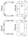
- These have a rounded shape at their ends and, according to the present invention, the lower or internal one, housed in the hollow 10 and bearing the reference number 22, extends mainly in the longitudinal direction with respect to the outer one 21, as is better seen in Fig. 2b.
- sloped or beveled surfaces can be provided to make easier the plugging into the slot 3.
- Insert member 2 of rigid material, such as metal or plastic material, is so sized and shaped to cause the edge of slot 3 to match with the groove 4 without slack.
- the elasticity of the material enables the insert member to pass through the slot by means of a temporary stretching of its contour until assuming the position indicated in Fig. 1a, wherein the rear wall 1a of the gasket is hold in the groove 4 between the two elements 21 and 22 which are just spaced apart substantially by the thickness size of said surface.
- the central flange 20 is pierced and the through hole 5, passing through both elements 21 and 22, is such to allow the insertion of an anchoring tongue protruding from the abutment surface, as it will be better explained in the following.
- This through hole 5 may have a shape reproducing, in a reduced scale, the slot 3 shape, as represented in Figs. 1-2, or a different one such as the "bayonet" shape of hole 5' as shown in Fig. 2.
- the insert member 2 can also have, instead of the straight shape represented in Figs. 1-3, the bent shape of Fig. 3a, particularly suitable when the members 2 are to be positioned in the corner zones of the gasket, as shown in Fig.4.
- the internal element 22 will extend along a substantially longer length with respect to the external element 21, with a length difference greater than that shown, preferably but not necessarily, by the straight insert of Figs. 2 and 3. Therefore element 22 forms a guide useful to make the gasket to assume the bent shape requested in the comer zones.
- the door backing frame 7, or abutment surface against which the door has to be shut tight by means of gasket 1 shows four wings 6 projecting to the outside to the corner zones of the frame itself, as shown in Fig. 4a. These wings are easily inserted, with a rapid radial movement towards the hollow space closed through the door and with slight stretch, into the through holes 5 of inserts 2 in their bent version of Fig.
- This gasket could be possibly closed by means of a blind insert (of known type) for butt-joining the two tips, formed for example merely by a strap slipped into both ends of the inner hollow 10 of the facing tips of the gasket.
- FIG. 5 and 5a there is shown another possible example of anchoring the gasket, of the three-side type in this case, showing six straight insert members 2 to be coupled with six corresponding straight tongues 8 represented in Fig. 5a.
- the arrangement of Figs. 6 and 6a could be adopted wherein, for a three-side gasket, two straight inserts and two bent ones are sufficient, these latter in the two comer zones.
- the advantage of the solution of Fig. 5 is that of having only one type of inserts to be available, all of the straight type, which can be easily obtained for example by metal stamping or molding of plastic material, possibly thermoplastics.
- all straight inserts could be used also in case of four-side gasket, thus replacing each bent insert with two straight ones placed on the two sides adjoining at the same comer, in the proximity thereof.
Landscapes
- Engineering & Computer Science (AREA)
- Chemical & Material Sciences (AREA)
- Combustion & Propulsion (AREA)
- Mechanical Engineering (AREA)
- General Engineering & Computer Science (AREA)
- Gasket Seals (AREA)
- Sealing Material Composition (AREA)
Abstract
Description
Claims (7)
- A frame-type sealing gasket, having three or four sides, in particular for doors of domestic cooking ovens or household appliances in general, comprising a tubular elongated element (1) of elastic material with longitudinal inner hollow (10) and frontally projecting continuous peripheral wing (11), the rear wall (1a) of which, opposed to said wing (11) being formed with elongated slots (3) spaced apart from each other and obtained by removal of material, each slot (3) having therein a rigid insert member (2) with central through hole (5, 5'), wherein said insert member (2) is comprised of two elements (21, 22) substantially flat and parallel, spaced apart from each other and coupled in the central zone by means of a joining flange (20) crossed by said through hole (5, 5') and having its periphery shaped as a U groove (4) for housing without clearance the inner edge of said slot (3), characterized in that said substantially flat and parallel elements (21, 22), forming the insert member (2) have different lengths, the lower one (22), housed in the inner hollow (10), being the more extended one.
- A gasket according to claim 1, wherein the distance between said two elements (21, 22) corresponds substantially to the thickness of the rear wall (1a), opposite to the wing (11) of the elongated element (1).
- A gasket according to claim 1 or 2, wherein said slots (3) and said inserts (2) have rounded ends.
- A gasket according to claim 3, wherein the central through hole (5) of the insert member (2) reproduces, in a reduced scale, the shape of said slot (3).
- A gasket according to claim 3, wherein the through hole (5') in said insert (2) has a shape non homologous thereto, of the bayonet-type.
- A gasket according to anyone of claims 1-5, wherein said inserts (20) are straight-lined for being coupled with corresponding tongues (8) protruding from the sides of a door abutment surface frame (7) against which the gasket is designed to provide tightness.
- A gasket according to anyone of claims 1-6, wherein, in correspondence of both comers, if of the three-side type, or of at least two comers, if of the four-side type, said insert members (2) are bent for coupling with corresponding wings (6) radially projecting to the outside from the comer zones of a surface of door abutment (7).
Applications Claiming Priority (1)
| Application Number | Priority Date | Filing Date | Title |
|---|---|---|---|
| PCT/IT1999/000335 WO2001029485A1 (en) | 1999-10-21 | 1999-10-21 | Elastomeric sealing gasket, particularly for doors of cooking domestic ovens or household appliances in general |
Publications (2)
| Publication Number | Publication Date |
|---|---|
| EP1147342A1 EP1147342A1 (en) | 2001-10-24 |
| EP1147342B1 true EP1147342B1 (en) | 2003-12-17 |
Family
ID=11333129
Family Applications (1)
| Application Number | Title | Priority Date | Filing Date |
|---|---|---|---|
| EP99954347A Expired - Lifetime EP1147342B1 (en) | 1999-10-21 | 1999-10-21 | Elastomeric sealing gasket, particularly for doors of cooking domestic ovens or household appliances in general |
Country Status (4)
| Country | Link |
|---|---|
| EP (1) | EP1147342B1 (en) |
| AT (1) | ATE256845T1 (en) |
| DE (1) | DE69913740D1 (en) |
| WO (1) | WO2001029485A1 (en) |
Families Citing this family (2)
| Publication number | Priority date | Publication date | Assignee | Title |
|---|---|---|---|---|
| CN101929693A (en) * | 2009-06-26 | 2010-12-29 | 博西华电器(江苏)有限公司 | Gas stove pan bracket and manufacturing method thereof |
| WO2014097180A2 (en) * | 2012-12-19 | 2014-06-26 | Indesit Company S.P.A. | Oven and method for attaching a seal thereof |
Family Cites Families (4)
| Publication number | Priority date | Publication date | Assignee | Title |
|---|---|---|---|---|
| US4417420A (en) * | 1981-02-11 | 1983-11-29 | Marsh Industries, Inc. | Door seal |
| GB2106974B (en) | 1981-10-06 | 1985-08-29 | Silicone Altimex Ltd | Door seal |
| DE3222671C2 (en) | 1982-06-16 | 1984-05-17 | Metzeler Kautschuk GmbH, 8000 München | Arrangement for sealing a door that closes a Bachofen muffle |
| EP0277098B1 (en) | 1987-01-21 | 1992-04-29 | GIAT S.r.L. | Improved gasket of elastomer material in the form of a closed or open frame for cooking oven doors |
-
1999
- 1999-10-21 AT AT99954347T patent/ATE256845T1/en not_active IP Right Cessation
- 1999-10-21 WO PCT/IT1999/000335 patent/WO2001029485A1/en not_active Ceased
- 1999-10-21 DE DE69913740T patent/DE69913740D1/en not_active Expired - Lifetime
- 1999-10-21 EP EP99954347A patent/EP1147342B1/en not_active Expired - Lifetime
Also Published As
| Publication number | Publication date |
|---|---|
| WO2001029485A1 (en) | 2001-04-26 |
| DE69913740D1 (en) | 2004-01-29 |
| ATE256845T1 (en) | 2004-01-15 |
| EP1147342A1 (en) | 2001-10-24 |
Similar Documents
| Publication | Publication Date | Title |
|---|---|---|
| RU2003125639A (en) | ADVANCED SEALING UNIT FOR REFRIGERATING CHAMBERS AND SIMILAR DEVICES HAVING A PLASTIC COMPLETE PROFILE | |
| CN101680703B (en) | Domestic appliance | |
| RU2390818C2 (en) | Sealing gasket to be installed under adjusting handle of kitchen stove | |
| US5606828A (en) | Magnetic door gasket | |
| EP0277098B1 (en) | Improved gasket of elastomer material in the form of a closed or open frame for cooking oven doors | |
| GB2106974A (en) | Door seal | |
| EP1415101B1 (en) | Appliance with seal between two housing shells | |
| US5066050A (en) | Dryer transition duct | |
| EP0757209B1 (en) | Elastomeric sealing gasket, particularly for cooking oven doors | |
| EP1147342A1 (en) | Elastomeric sealing gasket, particularly for doors of cooking domestic ovens or household appliances in general | |
| EP2772693B1 (en) | Encasing for household appliances | |
| GB2322073A (en) | Cover for domestic appliance | |
| CN110036242B (en) | Household cooking appliance | |
| MY126784A (en) | Microwave oven | |
| EP0992740A1 (en) | Elastomeric sealing gasket for cooking ovens | |
| NO180735B (en) | Lysraster | |
| RU201041U1 (en) | HARPOON FOR ATTACHING A STRETCH CEILING | |
| KR19980086760A (en) | Plastic parts | |
| EP0346631A1 (en) | Detergent dispensing device for dishwashing machines | |
| EP0040972B1 (en) | Gasket arrangement | |
| GB2269845A (en) | Connector for double glazing spacer bar | |
| EP0705415A1 (en) | Floating magnetic gasket, in particular for refrigerator doors | |
| HU224023B1 (en) | Drive rod fitting with corner deflection | |
| KR19980062984U (en) | Door Handle Assembly Structure of Refrigerator | |
| EP4356811A1 (en) | A dishwasher comprising an inner illumination member |
Legal Events
| Date | Code | Title | Description |
|---|---|---|---|
| PUAI | Public reference made under article 153(3) epc to a published international application that has entered the european phase |
Free format text: ORIGINAL CODE: 0009012 |
|
| 17P | Request for examination filed |
Effective date: 20010611 |
|
| AK | Designated contracting states |
Kind code of ref document: A1 Designated state(s): AT BE CH CY DE DK ES FI FR GB GR IE IT LI LU MC NL PT SE |
|
| 17Q | First examination report despatched |
Effective date: 20030220 |
|
| GRAH | Despatch of communication of intention to grant a patent |
Free format text: ORIGINAL CODE: EPIDOS IGRA |
|
| GRAS | Grant fee paid |
Free format text: ORIGINAL CODE: EPIDOSNIGR3 |
|
| GRAA | (expected) grant |
Free format text: ORIGINAL CODE: 0009210 |
|
| AK | Designated contracting states |
Kind code of ref document: B1 Designated state(s): AT BE CH CY DE DK ES FI FR GB GR IE IT LI LU MC NL PT SE |
|
| PG25 | Lapsed in a contracting state [announced via postgrant information from national office to epo] |
Ref country code: NL Free format text: LAPSE BECAUSE OF FAILURE TO SUBMIT A TRANSLATION OF THE DESCRIPTION OR TO PAY THE FEE WITHIN THE PRESCRIBED TIME-LIMIT Effective date: 20031217 Ref country code: LI Free format text: LAPSE BECAUSE OF FAILURE TO SUBMIT A TRANSLATION OF THE DESCRIPTION OR TO PAY THE FEE WITHIN THE PRESCRIBED TIME-LIMIT Effective date: 20031217 Ref country code: FR Free format text: LAPSE BECAUSE OF FAILURE TO SUBMIT A TRANSLATION OF THE DESCRIPTION OR TO PAY THE FEE WITHIN THE PRESCRIBED TIME-LIMIT Effective date: 20031217 Ref country code: FI Free format text: LAPSE BECAUSE OF FAILURE TO SUBMIT A TRANSLATION OF THE DESCRIPTION OR TO PAY THE FEE WITHIN THE PRESCRIBED TIME-LIMIT Effective date: 20031217 Ref country code: CY Free format text: LAPSE BECAUSE OF FAILURE TO SUBMIT A TRANSLATION OF THE DESCRIPTION OR TO PAY THE FEE WITHIN THE PRESCRIBED TIME-LIMIT Effective date: 20031217 Ref country code: CH Free format text: LAPSE BECAUSE OF FAILURE TO SUBMIT A TRANSLATION OF THE DESCRIPTION OR TO PAY THE FEE WITHIN THE PRESCRIBED TIME-LIMIT Effective date: 20031217 Ref country code: BE Free format text: LAPSE BECAUSE OF FAILURE TO SUBMIT A TRANSLATION OF THE DESCRIPTION OR TO PAY THE FEE WITHIN THE PRESCRIBED TIME-LIMIT Effective date: 20031217 Ref country code: AT Free format text: LAPSE BECAUSE OF FAILURE TO SUBMIT A TRANSLATION OF THE DESCRIPTION OR TO PAY THE FEE WITHIN THE PRESCRIBED TIME-LIMIT Effective date: 20031217 |
|
| RAP1 | Party data changed (applicant data changed or rights of an application transferred) |
Owner name: G.I.A.T. S.P.A. |
|
| REG | Reference to a national code |
Ref country code: GB Ref legal event code: FG4D |
|
| REG | Reference to a national code |
Ref country code: CH Ref legal event code: EP |
|
| REG | Reference to a national code |
Ref country code: IE Ref legal event code: FG4D |
|
| REF | Corresponds to: |
Ref document number: 69913740 Country of ref document: DE Date of ref document: 20040129 Kind code of ref document: P |
|
| PG25 | Lapsed in a contracting state [announced via postgrant information from national office to epo] |
Ref country code: SE Free format text: LAPSE BECAUSE OF FAILURE TO SUBMIT A TRANSLATION OF THE DESCRIPTION OR TO PAY THE FEE WITHIN THE PRESCRIBED TIME-LIMIT Effective date: 20040317 Ref country code: GR Free format text: LAPSE BECAUSE OF FAILURE TO SUBMIT A TRANSLATION OF THE DESCRIPTION OR TO PAY THE FEE WITHIN THE PRESCRIBED TIME-LIMIT Effective date: 20040317 Ref country code: DK Free format text: LAPSE BECAUSE OF FAILURE TO SUBMIT A TRANSLATION OF THE DESCRIPTION OR TO PAY THE FEE WITHIN THE PRESCRIBED TIME-LIMIT Effective date: 20040317 |
|
| PG25 | Lapsed in a contracting state [announced via postgrant information from national office to epo] |
Ref country code: DE Free format text: LAPSE BECAUSE OF FAILURE TO SUBMIT A TRANSLATION OF THE DESCRIPTION OR TO PAY THE FEE WITHIN THE PRESCRIBED TIME-LIMIT Effective date: 20040318 |
|
| PG25 | Lapsed in a contracting state [announced via postgrant information from national office to epo] |
Ref country code: ES Free format text: LAPSE BECAUSE OF FAILURE TO SUBMIT A TRANSLATION OF THE DESCRIPTION OR TO PAY THE FEE WITHIN THE PRESCRIBED TIME-LIMIT Effective date: 20040328 |
|
| NLV1 | Nl: lapsed or annulled due to failure to fulfill the requirements of art. 29p and 29m of the patents act | ||
| REG | Reference to a national code |
Ref country code: CH Ref legal event code: PL |
|
| PG25 | Lapsed in a contracting state [announced via postgrant information from national office to epo] |
Ref country code: LU Free format text: LAPSE BECAUSE OF NON-PAYMENT OF DUE FEES Effective date: 20041021 Ref country code: IE Free format text: LAPSE BECAUSE OF NON-PAYMENT OF DUE FEES Effective date: 20041021 Ref country code: GB Free format text: LAPSE BECAUSE OF NON-PAYMENT OF DUE FEES Effective date: 20041021 |
|
| PLBE | No opposition filed within time limit |
Free format text: ORIGINAL CODE: 0009261 |
|
| PG25 | Lapsed in a contracting state [announced via postgrant information from national office to epo] |
Ref country code: MC Free format text: LAPSE BECAUSE OF NON-PAYMENT OF DUE FEES Effective date: 20041031 |
|
| 26N | No opposition filed |
Effective date: 20040920 |
|
| EN | Fr: translation not filed | ||
| GBPC | Gb: european patent ceased through non-payment of renewal fee |
Effective date: 20041021 |
|
| REG | Reference to a national code |
Ref country code: IE Ref legal event code: MM4A |
|
| PG25 | Lapsed in a contracting state [announced via postgrant information from national office to epo] |
Ref country code: PT Free format text: LAPSE BECAUSE OF NON-PAYMENT OF DUE FEES Effective date: 20040517 |
|
| PGFP | Annual fee paid to national office [announced via postgrant information from national office to epo] |
Ref country code: IT Payment date: 20141028 Year of fee payment: 16 |
|
| PG25 | Lapsed in a contracting state [announced via postgrant information from national office to epo] |
Ref country code: IT Free format text: LAPSE BECAUSE OF NON-PAYMENT OF DUE FEES Effective date: 20151021 |