EP1146745A2 - Coding device and coding method - Google Patents
Coding device and coding method Download PDFInfo
- Publication number
- EP1146745A2 EP1146745A2 EP01302094A EP01302094A EP1146745A2 EP 1146745 A2 EP1146745 A2 EP 1146745A2 EP 01302094 A EP01302094 A EP 01302094A EP 01302094 A EP01302094 A EP 01302094A EP 1146745 A2 EP1146745 A2 EP 1146745A2
- Authority
- EP
- European Patent Office
- Prior art keywords
- tmin
- code volume
- video packet
- unit image
- represented
- Prior art date
- Legal status (The legal status is an assumption and is not a legal conclusion. Google has not performed a legal analysis and makes no representation as to the accuracy of the status listed.)
- Granted
Links
Images




Classifications
-
- H—ELECTRICITY
- H04—ELECTRIC COMMUNICATION TECHNIQUE
- H04N—PICTORIAL COMMUNICATION, e.g. TELEVISION
- H04N21/00—Selective content distribution, e.g. interactive television or video on demand [VOD]
- H04N21/20—Servers specifically adapted for the distribution of content, e.g. VOD servers; Operations thereof
- H04N21/23—Processing of content or additional data; Elementary server operations; Server middleware
- H04N21/234—Processing of video elementary streams, e.g. splicing of video streams or manipulating encoded video stream scene graphs
- H04N21/23406—Processing of video elementary streams, e.g. splicing of video streams or manipulating encoded video stream scene graphs involving management of server-side video buffer
-
- H—ELECTRICITY
- H04—ELECTRIC COMMUNICATION TECHNIQUE
- H04N—PICTORIAL COMMUNICATION, e.g. TELEVISION
- H04N19/00—Methods or arrangements for coding, decoding, compressing or decompressing digital video signals
- H04N19/10—Methods or arrangements for coding, decoding, compressing or decompressing digital video signals using adaptive coding
- H04N19/102—Methods or arrangements for coding, decoding, compressing or decompressing digital video signals using adaptive coding characterised by the element, parameter or selection affected or controlled by the adaptive coding
- H04N19/115—Selection of the code volume for a coding unit prior to coding
-
- H—ELECTRICITY
- H04—ELECTRIC COMMUNICATION TECHNIQUE
- H04N—PICTORIAL COMMUNICATION, e.g. TELEVISION
- H04N19/00—Methods or arrangements for coding, decoding, compressing or decompressing digital video signals
- H04N19/10—Methods or arrangements for coding, decoding, compressing or decompressing digital video signals using adaptive coding
- H04N19/134—Methods or arrangements for coding, decoding, compressing or decompressing digital video signals using adaptive coding characterised by the element, parameter or criterion affecting or controlling the adaptive coding
- H04N19/136—Incoming video signal characteristics or properties
- H04N19/137—Motion inside a coding unit, e.g. average field, frame or block difference
- H04N19/139—Analysis of motion vectors, e.g. their magnitude, direction, variance or reliability
-
- H—ELECTRICITY
- H04—ELECTRIC COMMUNICATION TECHNIQUE
- H04N—PICTORIAL COMMUNICATION, e.g. TELEVISION
- H04N19/00—Methods or arrangements for coding, decoding, compressing or decompressing digital video signals
- H04N19/10—Methods or arrangements for coding, decoding, compressing or decompressing digital video signals using adaptive coding
- H04N19/134—Methods or arrangements for coding, decoding, compressing or decompressing digital video signals using adaptive coding characterised by the element, parameter or criterion affecting or controlling the adaptive coding
- H04N19/146—Data rate or code amount at the encoder output
- H04N19/15—Data rate or code amount at the encoder output by monitoring actual compressed data size at the memory before deciding storage at the transmission buffer
-
- H—ELECTRICITY
- H04—ELECTRIC COMMUNICATION TECHNIQUE
- H04N—PICTORIAL COMMUNICATION, e.g. TELEVISION
- H04N19/00—Methods or arrangements for coding, decoding, compressing or decompressing digital video signals
- H04N19/10—Methods or arrangements for coding, decoding, compressing or decompressing digital video signals using adaptive coding
- H04N19/169—Methods or arrangements for coding, decoding, compressing or decompressing digital video signals using adaptive coding characterised by the coding unit, i.e. the structural portion or semantic portion of the video signal being the object or the subject of the adaptive coding
- H04N19/17—Methods or arrangements for coding, decoding, compressing or decompressing digital video signals using adaptive coding characterised by the coding unit, i.e. the structural portion or semantic portion of the video signal being the object or the subject of the adaptive coding the unit being an image region, e.g. an object
- H04N19/176—Methods or arrangements for coding, decoding, compressing or decompressing digital video signals using adaptive coding characterised by the coding unit, i.e. the structural portion or semantic portion of the video signal being the object or the subject of the adaptive coding the unit being an image region, e.g. an object the region being a block, e.g. a macroblock
-
- H—ELECTRICITY
- H04—ELECTRIC COMMUNICATION TECHNIQUE
- H04N—PICTORIAL COMMUNICATION, e.g. TELEVISION
- H04N19/00—Methods or arrangements for coding, decoding, compressing or decompressing digital video signals
- H04N19/10—Methods or arrangements for coding, decoding, compressing or decompressing digital video signals using adaptive coding
- H04N19/169—Methods or arrangements for coding, decoding, compressing or decompressing digital video signals using adaptive coding characterised by the coding unit, i.e. the structural portion or semantic portion of the video signal being the object or the subject of the adaptive coding
- H04N19/18—Methods or arrangements for coding, decoding, compressing or decompressing digital video signals using adaptive coding characterised by the coding unit, i.e. the structural portion or semantic portion of the video signal being the object or the subject of the adaptive coding the unit being a set of transform coefficients
-
- H—ELECTRICITY
- H04—ELECTRIC COMMUNICATION TECHNIQUE
- H04N—PICTORIAL COMMUNICATION, e.g. TELEVISION
- H04N19/00—Methods or arrangements for coding, decoding, compressing or decompressing digital video signals
- H04N19/10—Methods or arrangements for coding, decoding, compressing or decompressing digital video signals using adaptive coding
- H04N19/169—Methods or arrangements for coding, decoding, compressing or decompressing digital video signals using adaptive coding characterised by the coding unit, i.e. the structural portion or semantic portion of the video signal being the object or the subject of the adaptive coding
- H04N19/186—Methods or arrangements for coding, decoding, compressing or decompressing digital video signals using adaptive coding characterised by the coding unit, i.e. the structural portion or semantic portion of the video signal being the object or the subject of the adaptive coding the unit being a colour or a chrominance component
-
- H—ELECTRICITY
- H04—ELECTRIC COMMUNICATION TECHNIQUE
- H04N—PICTORIAL COMMUNICATION, e.g. TELEVISION
- H04N19/00—Methods or arrangements for coding, decoding, compressing or decompressing digital video signals
- H04N19/60—Methods or arrangements for coding, decoding, compressing or decompressing digital video signals using transform coding
-
- H—ELECTRICITY
- H04—ELECTRIC COMMUNICATION TECHNIQUE
- H04N—PICTORIAL COMMUNICATION, e.g. TELEVISION
- H04N19/00—Methods or arrangements for coding, decoding, compressing or decompressing digital video signals
- H04N19/60—Methods or arrangements for coding, decoding, compressing or decompressing digital video signals using transform coding
- H04N19/61—Methods or arrangements for coding, decoding, compressing or decompressing digital video signals using transform coding in combination with predictive coding
-
- H—ELECTRICITY
- H04—ELECTRIC COMMUNICATION TECHNIQUE
- H04N—PICTORIAL COMMUNICATION, e.g. TELEVISION
- H04N19/00—Methods or arrangements for coding, decoding, compressing or decompressing digital video signals
- H04N19/70—Methods or arrangements for coding, decoding, compressing or decompressing digital video signals characterised by syntax aspects related to video coding, e.g. related to compression standards
-
- H—ELECTRICITY
- H04—ELECTRIC COMMUNICATION TECHNIQUE
- H04N—PICTORIAL COMMUNICATION, e.g. TELEVISION
- H04N21/00—Selective content distribution, e.g. interactive television or video on demand [VOD]
- H04N21/20—Servers specifically adapted for the distribution of content, e.g. VOD servers; Operations thereof
- H04N21/23—Processing of content or additional data; Elementary server operations; Server middleware
- H04N21/235—Processing of additional data, e.g. scrambling of additional data or processing content descriptors
-
- H—ELECTRICITY
- H04—ELECTRIC COMMUNICATION TECHNIQUE
- H04N—PICTORIAL COMMUNICATION, e.g. TELEVISION
- H04N21/00—Selective content distribution, e.g. interactive television or video on demand [VOD]
- H04N21/40—Client devices specifically adapted for the reception of or interaction with content, e.g. set-top-box [STB]; Operations thereof
- H04N21/43—Processing of content or additional data, e.g. demultiplexing additional data from a digital video stream; Elementary client operations, e.g. monitoring of home network or synchronising decoder's clock; Client middleware
- H04N21/435—Processing of additional data, e.g. decrypting of additional data, reconstructing software from modules extracted from the transport stream
-
- H—ELECTRICITY
- H04—ELECTRIC COMMUNICATION TECHNIQUE
- H04N—PICTORIAL COMMUNICATION, e.g. TELEVISION
- H04N21/00—Selective content distribution, e.g. interactive television or video on demand [VOD]
- H04N21/40—Client devices specifically adapted for the reception of or interaction with content, e.g. set-top-box [STB]; Operations thereof
- H04N21/43—Processing of content or additional data, e.g. demultiplexing additional data from a digital video stream; Elementary client operations, e.g. monitoring of home network or synchronising decoder's clock; Client middleware
- H04N21/44—Processing of video elementary streams, e.g. splicing a video clip retrieved from local storage with an incoming video stream or rendering scenes according to encoded video stream scene graphs
- H04N21/44004—Processing of video elementary streams, e.g. splicing a video clip retrieved from local storage with an incoming video stream or rendering scenes according to encoded video stream scene graphs involving video buffer management, e.g. video decoder buffer or video display buffer
-
- H—ELECTRICITY
- H04—ELECTRIC COMMUNICATION TECHNIQUE
- H04N—PICTORIAL COMMUNICATION, e.g. TELEVISION
- H04N19/00—Methods or arrangements for coding, decoding, compressing or decompressing digital video signals
- H04N19/90—Methods or arrangements for coding, decoding, compressing or decompressing digital video signals using coding techniques not provided for in groups H04N19/10-H04N19/85, e.g. fractals
- H04N19/91—Entropy coding, e.g. variable length coding [VLC] or arithmetic coding
Definitions
- the present invention relates to a coding device and a coding method for coding a video signal by using a video packet having a length limit set thereto which is related to a portable telephone, a TV telephone system and the like, for example.
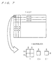
- Fig. 6 is a block diagram showing a conventional coding device described in "Everything about MPEG - 4" (Institute of Industrial Research) P. 39 to P. 40, for example, Fig. 7 is a diagram illustrating an input signal of the conventional coding device, Figs. 8A to 8D are diagrams illustrating a structure of a bit stream, and Fig. 9 is a diagram illustrating a position (arrangement) of a video packet over a screen (display state).
- the reference numeral 1 denotes a subtracter for receiving an external input signal (a luminance signal, a color difference signal or the like) sent externally as a first input.
- An output of the subtracter 1 is input to a DC / AC predictor 4 for predicting a quantized value of each component of a direct current (DC) and an alternating current (AC) and a reverse quantizer 6 through DCT (Discrete Cosine Transform) means 2 and a quantizer 3.
- DC direct current
- AC alternating current
- DCT Discrete Cosine Transform
- an output of the reverse quantizer 6 to which an output of the quantizer 3 is input is sent to a first input of an adder 8 through reverse DCT means 7.
- An output of the adder 8 is sent to a memory 9, and an output of the memory 9 is sent to a first input of predicted image forming means 10 and a first input of motion detecting means 11.
- An external input signal is sent to a second input of the motion detecting means 11, and an output of the motion detecting means 11 is sent to a second input of the predicted image forming means 10 and a motion vector predictor 12.
- An output of the motion vector predictor 12 is sent to a second input of the variable - length coding means 5. Moreover, an output of the predicted image forming means 10 is sent to a second input of the subtracter 1 and a second input of the adder 8.
- a video signal is divided into macroblocks to be basic processing units as shown in Fig. 7 and is input as an external input signal (the external input signal is basically input as a macroblock, and means for generating a macroblock may be provided in a former stage such that a conversion into a macroblock is carried out even if the macroblock is directly input) .
- a size of 16 pixels x 16 lines of the luminance signal (Y) becomes equal to that of 8 pixels x 8 lines of two color difference signals (Cb, Cr) over a screen.
- six blocks of 8 pixels x 8 lines (including four blocks for the luminance signal and two blocks for the color difference signal) constitute one macroblock.
- VOP Video Object Plane
- Each block is subjected to the discrete cosine transform (DCT) and is quantized in the quantizer 3.
- DCT discrete cosine transform
- intracoding which is also referred to as in - frame coding.
- a VOP applying the intracoding to all the macroblocks is referred to as an I-VOP (Intra - VOP).
- the quantized DCT coefficient is reversely quantized in the reverse quantizer 6 and is decoded by the reverse DCT in the reverse DCT means 7, and a decoded image is stored in the memory 9 through the adder 8.
- the decoded image stored in the memory 9 is used when intercoding (which is also referred to as interframe coding) is to be carried out.
- a motion vector indicative of a motion of a macroblock which is input as an external input signal is detected in the motion detecting means 11.
- the motion vector indicates such a position that an error is minimized with respect to the input macroblock in the decoded images stored in the memory 9.
- the predicted image forming means 10 forms a predicted image based on the motion vector detected by the motion detecting means 11.
- a differential signal between the input macroblock and the predicted image formed by the predicted image forming means 10 is obtained, is subjected to the DCT in the DCT means 2 and is quantized in the quantizer 3.
- a transformation coefficient thus quantized is variable - length coded (intercoded) together with the motion vector thus predicted and coded and additional information such as a quantization parameter.
- the quantized DCT coefficient is reversely quantized in the reverse quantizer 6 and is subjected to the reverse DCT in the reverse DCT means 7, and is then added to the predicted image by the adder 8 and is stored in the memory 9.
- the intercoding includes one - way prediction in which prediction is carried out based on only a former VOP on a time basis in order of display of the image and bidirectional prediction in which prediction is carried out based on former and latter VOPs on a time basis.
- the VOP coded through the one - way prediction will be referred to as a P - VOP (Predictive VOP) and the VOP coded through the bi-directional prediction will be referred to as a B - VOP (Bidirectionally Predictive VOP).
- a bit stream of 1VOP is constituted by (a bit stream of) one video packet or more.
- One video packet is formed by coded data of one macroblock or more.
- a VOP header is attached to a head and a stuff bit for a byte alignment is attached to an end (Fig. 8B).
- Resync Marker for detecting a head of the video packet and a video packet header are attached to a head, and a stuff bit is attached to an end (Fig. 8C).
- the stuff bit is added up to a termination (break) of the video packet in a unit of 1 to 8 bits in order to adjust the byte alignment to be attached to the end of the video packet and the meaning thereof is distinguished from that of a stuffing which will be described below.
- an optional number of stuffings can also be put in the video packet.
- the stuffing is referred to as a stuffing macroblock and can be put in an optional video packet in the same manner as the macroblock.
- the stuffing is discarded (is not substantially utilized) on the decoder side.
- the stuffing is used as a word having 9 bits or 10 bits for the stuffing irrespective of the byte alignment (for example, the termination of the video packet is adjusted) and is inserted between the macroblocks, of which meaning is distinguished from the meaning of the stuff bit.
- An optional number of macroblocks can be put in one video packet.
- a code volume of each video packet should be almost constant.
- a rate (area) occupied by each video packet in the 1VOP is not constant as shown in Fig. 9.
- the decoder decodes the variable - length code in a reverse direction from an end of the video packet even if an error is made in an operation for decoding the variable - length code in a forward direction from a head of the video packet.
- the variable - length code can be decoded.
- a limit is sometimes set to a length of the video packet in order to define a size of the receiving buffer.
- a coding device should control a code volume such that the length of each video packet is set to be a predetermined length or less.
- the coding device should manage a volume of generated codes such that a transmitting buffer (not shown) which is provided in a latter stage of the variable-length coding means 5 does not cause an overflow and an underflow.
- the quantization parameter to be used in the quantizer 3 is usually adjusted to increase or decrease the code volume. If the code volume is extremely small as in a static image, it is necessary to insert the stuffing, thereby increasing the code volume such that the transmitting buffer does not cause the underflow.
- the stuffing does not have information which is substantially related to the decoding. Therefore, it is desirable that the stuffing should not be inserted if possible. For this reason, generally, a minimum stuffing is inserted if the code volume is small after the 1VOP is completely coded.
- the stuffing cannot perfectly enter one video packet when the stuffing is inserted after the 1VOP is completely coded.
- a first aspect of the present invention is directed to a coding device comprising coding means for coding an external input signal in a macroblock unit, first storing means for storing a code output from the coding means, second storing means for storing an output from the first storing means, and code volume control means for controlling transfer of the code stored in the first storing means to the second storing means based on a code volume of the code obtained by the coding means such that a length of a video packet constituted by the code is a predetermined length or less.
- a second aspect of the present invention is directed to the coding device, wherein the code volume control means controls storage of a stuffing in the second storing means based on a minimum code volume obtained for each unit image constituted by a video packet which is required for coding the unit image.
- a sixth aspect of the present invention is directed to the coding device, wherein the bit rate R read from the second storing means is variable.
- a seventh aspect of the present invention is directed to the coding device, wherein the code volume control means inserts a stuffing into a video packet until a first relationship is not satisfied, when a present code volume of a unit image including a last coded macroblock constituting the unit image is smaller than the minimum code volume Tmin of the unit image and a number M of macroblocks to be coded subsequently to the last coded macroblock, a predetermined length VPlen of the video packet, the minimum code volume Tmin and the present code volume Sc have the first relationship: M ⁇ VPlen ⁇ Tmin - Sc, the code volume control means constitutes a video packet next to the video packet by a macroblock next to the last coded macroblock without inserting a stuffing into the video packet, when the first relationship is not established and the number M of macroblocks, the length VPlen of a video packet, the minimum code volume Tmin and the present code volume Sc have a second relationship: (M - 1 ) ⁇ VPlen ⁇ Tmin -
- An eighth aspect of the present invention is directed to a coding method comprising the steps of (a) coding an external input signal in a macroblock unit, (b) storing a code obtained at the step (a), (c) controlling an output of the code stored at the step (b) such that a length of a video packet constituted by the code obtained at the step (a) is a predetermined length or less based on a code volume of the code, and (d) storing the output controlled by the step (c).
- a ninth aspect of the present invention is directed to the coding method, wherein the step (c) serves to control storage of a stuffing at the step (d) based on a minimum code volume obtained for each unit image constituted by a video packet which is required for coding the unit image.
- a thirteenth aspect of the present invention is directed to the coding method, wherein the bit rate R at which a code stored at the step (d) is read is variable.
- a fourteenth aspect of the present invention is directed to the coding method, wherein the step (c) serves to insert a stuffing into a video packet until a first relationship is not satisfied, when a present code volume of a unit image including a last coded macroblock constituting the unit image is smaller than the minimum code volume Tmin of the unit image and a number M of macroblocks to be coded subsequently to the last coded macroblock, a predetermined length VPlen of the video packet, the minimum code volume Tmin and a present code volume Sc have a first relationship: M x VPlen ⁇ Tmin - Sc, the code volume controlling step serves to constitute a video packet next to the video packet by a macroblock next to the last coded macroblock without inserting a stuffing into the video packet, when the first relationship is not established and the number M of macroblocks, the length VPlen of a video packet, the minimum code volume Tmin and the present code volume Sc have a second relationship: (M - 1) x VPlen ⁇ T
- the above-mentioned structure can give the following effects.
- the coding device comprises coding means for coding an external input signal in a macroblock unit, first storing means for storing a code output from the coding means, second storing means for storing an output from the first storing means, and code volume control means for controlling transfer of the code stored in the first storing means to the second storing means based on a code volume of the code obtained by the coding means such that a length of a video packet constituted by the code is a predetermined length or less. Also in the case in which the video packet has a length limit, therefore, a structure thereof can be obtained corresponding to the limit.
- the code volume control means in the coding device controls storage of a stuffing in the second storing means based on a minimum code volume obtained for each unit image required for coding the unit image constituted by a video packet. Also in the case of an image having a small generated code volume such as a static image, therefore, it is possible to insert a minimum stuffing.
- the bit rate R read from the second storing means is variable. Therefore, the underflow of the second storing means or the overflow of the VBV buffer can be avoided effectively.
- a predetermined length VPlen of a video packet, the minimum code volume Tmin and a present code volume Sc have a first relationship: M ⁇ VPlen ⁇ Tmin - Sc
- the code volume control means in the coding device inserts a stuffing into the video packet until the first relationship is not satisfied, and when the first relationship is not established and the number M of macroblocks, the length VPlen of a video packet, the minimum code volume Tmin and the present code volume Sc have a second relationship: (M - 1) ⁇ VPlen ⁇ Tmin - Sc
- the code volume control means constitutes a video packet next to the video packet by a macroblock next to the last coded macroblock without inserting a stuffing into the video packet. Therefore
- the coding method comprises the steps of (a) coding an external input signal in a macroblock unit, (b) storing a code obtained at the coding step, (c) controlling an output of the code stored at the step (b) such that a length of a video packet constituted by the code is a predetermined length or less based on a code volume of the code obtained at the step (a) , and (d) storing the output controlled at the step (c). Therefore, also in the case in which the video packet has a length limit, a structure thereof can be obtained corresponding to the limit.
- the step (c) in the coding method serves to control storage of a stuffing at the step (d) based on a minimum code volume obtained for each unit image constituted by a video packet which is required for coding the unit image. Also in the case of an image having a small generated code volume such as a static image, therefore, it is possible to insert a minimum stuffing.
- the bit rate R at which a code stored at the step (d) is read is variable. Therefore, the underflow of the second storing means or the overflow of the VBV buffer can be avoided effectively.
- a predetermined length VPlen of a video packet, the minimum code volume Tmin and a present code volume Sc have a first relationship: M ⁇ VPlen ⁇ Tmin- Sc
- the code volume controlling step in the coding method serves to insert a stuffing into the video packet until the first relationship is not satisfied, and when the first relationship is not established and the number M of macroblocks, the length VPlen of a video packet, the minimum code volume Tmin and the present code volume Sc have a second relationship: (M - 1) ⁇ VPlen ⁇ Tmin - Sc
- the step (c) serves to constitute a video packet next to a video packet by a macroblock next to the coded macroblock without inserting a stuffing into the video packet.
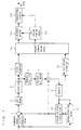
- Fig. 1 is a block diagram showing a coding device according to a first embodiment
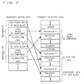
- Fig. 2 is a diagram illustrating a state of a temporary buffer and a transmitting buffer according to the first embodiment (in the case of an I - VOP),
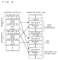
- Fig. 3 is a diagram illustrating a state of the temporary buffer and the transmitting buffer according to the first embodiment (in the case of a P - VOP),
- Fig. 4 is a flow chart for explaining an operation in the coding device according to the first embodiment
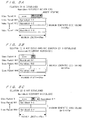
- Figs. 5A to 5C are diagrams showing a structure of a video packet according to the first embodiment
- Fig. 6 is a block diagram showing a conventional coding device
- Fig. 7 is a diagram showing an external input signal to be sent to the conventional coding device
- Figs. 8A to 8D are diagrams showing a structure of a bit stream in the conventional coding device.
- Fig. 9 is a diagram showing a position of a video packet over a screen in the conventional coding device.
- Fig. 1 shows a coding device according to a first embodiment of the present invention.
- the reference numeral 1 denotes a subtracter for receiving an external input signal as a first input.
- An output of the subtracter 1 is input to a DC/AC predictor 4 and a reverse quantizer 6 through DCT means 2 and a quantizer 3.
- An output of the DC/AC predictor 4 is sent to a first input of variable - length coding means 5a.
- an output of the reverse quantizer 6 is sent to a first input of an adder 8 through reverse DCT means 7.
- An output of the adder 8 is sent to a memory 9, and an output of the memory 9 is sent to a first input of predicted image forming means 10 and a first input of motion detecting means 11.
- the external input signal is sent to a second input of the motion detecting means 11, and an output of the motion detecting means 11 is sent to a second input of the predicted image forming means 10 and a motion vector predictor 12.
- An output of the predicted image forming means 10 is sent to a second input of the subtracter 1 and a second input of the adder 8.
- an output of the motion vector predictor 12 is sent to a second input of the variable - length coding means 5a.
- Coding means is constituted by inclusion from the subtracter 1 for inputting the external input signal to the variable - length coding means 5a for outputting a variable - length code corresponding to the external input signal (Of course, the structure is only illustrated as an example and a well - known structure capable of carrying out coding corresponding to the external input signal can be used).
- a first output of the variable - length coding means 5a is sent to a first input of a temporary buffer 101 (first storing means), and a second output of the variable - length coding means 5a is sent to an input of code volume control means 102.
- a first output of the code volume control means 102 is sent to a second input of the temporary buffer 101, and an output of the temporary buffer 101 is sent to a first input of a transmitting buffer 103 (second storing means).
- a second output of the code volume control means 102 is sent to a second input of the transmitting buffer 103, and an output of the transmitting buffer 103 is output (transmitted) as a bit stream.
- the bit stream thus output (transmitted) is received on the decoder side and is subjected to a decoding processing.
- a video signal is divided into macroblocks to be basic processing units as shown in Fig. 7 and is then input.
- the video signal to be input is 4 : 2 : 0
- a size of 16 pixels x 16 lines of a luminance signal (Y) is equal to that of 8 pixels x 8 lines of two color difference signals (Cb, Cr) over a screen. Therefore, one macroblock is constituted by six blocks, each of the blocks having 8 pixels x 8 lines.
- each block is subjected to DCT and is then quantized.
- a DCT coefficient thus quantized is predicted by the DC/AC predictor 4 and is then variable - length coded together with additional information such as a quantization parameter.
- the DCT coefficient thus quantized is decoded through reverse quantization and reverse DCT, and a decoded image is stored in the memory 9.
- the motion detecting means 11 detects a motion vector indicative of a motion of the input macroblock.
- the motion vector indicates such a position that the smallest error is made with respect to the input macroblock in the decoded image stored in the memory 9.
- the predicted image forming means 10 Based on the motion vector, the predicted image forming means 10 forms a predicted image. Next, a difference between the input macroblock and the predicted image is obtained so that a difference signal is subjected to the DCT and is quantized.
- the DCT coefficient thus quantized is variable - length coded together with the motion vector thus predicted and coded and the additional information such as the quantization parameter. Moreover, after the quantized DCT coefficient is subjected to the reverse quantization and the reverse DCT, it is added to the predicted image and is stored in the memory 9.
- variable - length coding means 5a Next, an operation of the variable - length coding means 5a will be described in detail.
- variable - length coding means 5a codes the quantized DCT coefficient and the additional information for each macroblock (a coding step), writes them to the temporary buffer 101 (a first storing step) and outputs a code volume thereof to the code volume control means 102.
- an AC component of the quantized DCT coefficient of each block is first one - dimensionally scanned by zigzag scan or the like, and run - length coding for coding a combination of the number of 0s and a coefficient of non - zero is carried out. Coefficient data of each block which are run - length coded are written to the temporary buffer 101.
- mcbpc obtained by collectively coding MTYPE indicative of a macroblock type and CBPC indicating whether each block for a color difference has a non - zero AC coefficient, dquant indicative of a quantization parameter, a DC component of a DCT coefficient of each block, ac_pred_flag indicating whether AC prediction is carried out, and cbpy indicating whether each block of Y has a non-zero AC coefficient are coded in order after the coefficient data of each block which are stored in the temporary buffer 101, and are written to the temporary buffer 101.
- a total of the code volumes is output to the code volume control means 102 for each macroblock.
- the code volume control means 102 collects macroblocks such that a length of each video packet has a predetermined value (VPlen) or less based on a code volume of each macroblock which is output from the variable - length coding means 5a (a code volume controlling step), and transfers them from the temporary buffer 101 to the transmitting buffer 103 (a second storing step).
- VPlen a predetermined value
- the code volume control means 102 collects macroblocks such that a length of each video packet has a predetermined value (VPlen) or less based on a code volume of each macroblock which is output from the variable - length coding means 5a (a code volume controlling step), and transfers them from the temporary buffer 101 to the transmitting buffer 103 (a second storing step).
- a header is added to a head of the video packet and is then rearranged and transferred to the transmitting buffer 103 in order of the defined bit stream as shown in Figs. 2 and 3.
- the code volume control means 102 sets a minimum code volume Tmin for each VOP such that the transmitting buffer 103 does not cause an underflow or a VBV (Video Buffering Verifier) buffer (a virtual buffer required for receiving a video packet on the receiving side (a required capacity is described in a header of a transmitting bit stream, for example). At least a capacity for the I - VOP is usually set.) does not cause an overflow, and writes a stuffing to the transmitting buffer 103 if necessary and determines a break of the video packet such that the code volume of the VOP is not smaller than the Tmin.
- VBV Video Buffering Verifier
- the minimum code volume Tmin implies a minimum code volume which is required such that the transmitting buffer 103 does not cause the underflow and the VBV buffer does not cause the overflow.
- the minimum code volume Tmin should be set as follows: Tmin ⁇ 2 ⁇ R p - B.
- an occupancy of the VBV buffer is vbv_bs - Rp or less such that the VBV buffer does not cause the overflow
- the occupancy of the VBV buffer (a data occupancy retained in the VBV buffer) for a time required for decoding a VOP prior to a current VOP is represented by vbv_bits (the occupancy of the VBV buffer) and a size of the VBV buffer is represented by vbv_bs.
- a minimum code volume Tmin of the current VOP should be set as follows: Tmin ⁇ vbv_bits + 2 ⁇ Rp - vbv_bs.
- the occupancy vbv_bits of the VBV buffer presumes an occupancy on the receiving side, and is calculated based on a read bit rate of the transmitting buffer 103, for example, it is changed with the passage of time.
- Tmin vbv_bits + 2 ⁇ R p - vbv_bs.
- the vbv_bits is changed on a time basis. Therefore, the value of the minimum code volume Tmin is also changed on a time basis and is calculated for each VOP.
- the code volume control means 102 calculates a present code volume Sc of the current VOP for each macroblock and decides whether a new video packet is to be constituted at a next macroblock or not and whether a stuffing is to be inserted into a current video packet or not in accordance with a flow chart shown in Fig. 4 and a structure of a video packet shown in Fig. 5.
- the total number of macroblocks constituting the VOP is represented by A
- a macroblock number of a current macroblock is represented by K (0 ⁇ K ⁇ A - 1)
- the macroblocks are collected to constitute a video packet such that a length of each video packet is VPlen or less as described above.
- M residual video packets can be constituted as shown in Fig. 5A if the number of residual macroblocks is M. Therefore, a code having a code volume of M ⁇ VPlen can be generated.
- a residual generated code volume of M ⁇ VPlen is obtained at a maximum as shown in Fig. 5B.
- a code volume for all the macroblocks constituting the VOP M ⁇ VPlen + Sc ⁇ Tmin Accordingly, it is not necessary to insert the stuffing into the current video packet.
- a structure of the video packet can be determined to insert a minimum stuffing under the restriction that a maximum length of the video packet is VPlen.
- the read rate of the transmitting buffer 103 is represented by R in the setting of the Tmin in the above-mentioned embodiment, similarly, the Tmin can be set such that the underflow of the transmitting buffer 103 or the overflow of the VBV buffer is not caused even if the read rate is not fixed but variable.
- the case in which the read rate of the transmitting buffer 103 is variable is equivalent to the case in which a maximum transmission rate is determined and is assigned depending on a type of information to be transmitted (such as a video or a speech), for example.
- the code volume is controlled based on the flow chart of Fig. 4. Consequently, the insertion of the stuffing and the break of the video packet can be determined to carry out control such that a code volume of each VOP is Tmin or more.
- a structure of (1) not_coded, mcbpc and motion vector, (2) cbpy and dquant and (3) coefficient data of each block may be stored in the transmitting buffer 103 as shown in Fig. 3, for example. Basically, it is preferable that the coefficient data of each block and additional information related to the coefficient data should be classified as categories. Moreover, (1) to (3) are not always required for the category and an optional number of categories can be permitted.
- an input signal is not 4 : 2 : 0 and the case in which a VOP (unit image) is not rectangular (for example, an optional shape which can be taken by an object in a screen).
Landscapes
- Engineering & Computer Science (AREA)
- Multimedia (AREA)
- Signal Processing (AREA)
- Compression Or Coding Systems Of Tv Signals (AREA)
Abstract
Description
when the first relationship is not established and the number M of macroblocks, the length VPlen of a video packet, the minimum code volume Tmin and the present code volume Sc have a second relationship: (M - 1) · VPlen < Tmin - Sc,
the code volume control means constitutes a video packet next to the video packet by a macroblock next to the last coded macroblock without inserting a stuffing into the video packet. Therefore, a video packet having only a stuffing can be prevented from being generated, and an underflow of a transmitting buffer or an overflow of the VBV buffer can be prevented by inserting a minimum stuffing.
when the first relationship is not established and the number M of macroblocks, the length VPlen of a video packet, the minimum code volume Tmin and the present code volume Sc have a second relationship: (M - 1) · VPlen < Tmin - Sc,
the step (c) serves to constitute a video packet next to a video packet by a macroblock next to the coded macroblock without inserting a stuffing into the video packet. Therefore, a video packet having only a stuffing can be prevented from being generated, and an underflow of a transmitting buffer or an overflow of the VBV buffer can be prevented by inserting a minimum stuffing.
Claims (10)
- A coding device comprising:coding means «5a» for coding an external input signal in a macroblock unit;first storing means «101» for storing a code output from said coding means;second storing means «103» for storing an output from said first storing means; andcode volume control means «102» for controlling transfer of said code stored in said first storing means to said second storing means based on a code volume of said code obtained by said coding means such that a length of a video packet constituted by said code is a predetermined length or less.
- The coding device according to claim 1, wherein
said code volume control means controls storage of a stuffing in said second storing means based on a minimum code volume obtained for each unit image constituted by a video packet which is required for coding said unit image. - The coding device according to claim 2, wherein
said code volume control means determines a minimum code volume Tmin to satisfy a following equation: - The coding device according to claim 2, wherein
said code volume control means determines a minimum code volume Tmin to satisfy a following equation: - The coding device according to claim 2, whereinsaid code volume control means inserts a stuffing into a video packet until a first relationship is not satisfied, when a present code volume of a unit image including a last coded macroblock constituting said unit image is smaller than said minimum code volume Tmin of said unit image and a number M of macroblocks to be coded subsequently to said last coded macroblock, a predetermined length VPlen of said video packet, said minimum code volume Tmin and said present code volume Sc have said first relationship:said code volume control means constitutes a video packet next to said video packet by a macroblock next to said last coded macroblock without inserting a stuffing into said video packet, when said first relationship is not established and said number M of macroblocks, said length VPlen of a video packet, said minimum code volume Tmin and said present code volume Sc have a second relationship:
- A coding method comprising the steps of:(a) coding an external input signal in a macroblock unit;(b) storing a code obtained at said step (a);(c) controlling an output of said code stored at said step (b) such that a length of a video packet constituted by said code obtained at said step (a) is a predetermined length or less based on a code volume of said code; and(d) storing said output controlled by said step (c).
- The coding method according to claim 6, wherein
said step (c) serves to control storage of a stuffing at said step (d) based on a minimum code volume obtained for each unit image constituted by a video packet which is required for coding said unit image. - The coding method according to claim 7, wherein
said step (c) serves to determine a minimum code volume Tmin to satisfy a following equation: - The coding method according to claim 7, wherein
said step (c) serves to determine a minimum code volume Tmin to satisfy a following equation: - The coding method according to claim 7, whereinsaid step (c) serves to insert a stuffing into a video packet until a first relationship is not satisfied, when a present code volume of a unit image including a last coded macroblock constituting said unit image is smaller than said minimum code volume Tmin of said unit image and a number M of macroblocks to be coded subsequently to said last coded macroblock, a predetermined length VPlen of said video packet, said minimum code volume Tmin and a present code volume Sc have a first relationship:said code volume controlling step serves to constitute a video packet next to said video packet by a macroblock next to said last coded macroblock without inserting a stuffing into said video packet, when said first relationship is not established and said number M of macroblocks, said length VPlen of a video packet, said minimum code volume Tmin and said present code volume Sc have a second relationship:
Applications Claiming Priority (2)
| Application Number | Priority Date | Filing Date | Title |
|---|---|---|---|
| JP2000063197 | 2000-03-08 | ||
| JP2000063197 | 2000-03-08 |
Publications (3)
| Publication Number | Publication Date |
|---|---|
| EP1146745A2 true EP1146745A2 (en) | 2001-10-17 |
| EP1146745A3 EP1146745A3 (en) | 2004-01-02 |
| EP1146745B1 EP1146745B1 (en) | 2019-09-04 |
Family
ID=18583100
Family Applications (1)
| Application Number | Title | Priority Date | Filing Date |
|---|---|---|---|
| EP01302094.6A Expired - Lifetime EP1146745B1 (en) | 2000-03-08 | 2001-03-07 | Coding device and coding method |
Country Status (3)
| Country | Link |
|---|---|
| US (1) | US6931069B2 (en) |
| EP (1) | EP1146745B1 (en) |
| CN (1) | CN1181692C (en) |
Families Citing this family (7)
| Publication number | Priority date | Publication date | Assignee | Title |
|---|---|---|---|---|
| US7346220B2 (en) * | 2003-07-23 | 2008-03-18 | Seiko Epson Corporation | Method and apparatus for reducing the bandwidth required to transmit image data |
| US7421130B2 (en) * | 2004-06-25 | 2008-09-02 | Seiko Epson Corporation | Method and apparatus for storing image data using an MCU buffer |
| US7386178B2 (en) * | 2004-07-29 | 2008-06-10 | Seiko Epson Corporation | Method and apparatus for transforming the dimensions of an image |
| US8015612B2 (en) * | 2007-04-27 | 2011-09-06 | Rogson Ariel S | Addressing security in writes to memory |
| US9462271B2 (en) * | 2010-07-15 | 2016-10-04 | Mitsubishi Electric Corporation | Moving image encoding device, moving image decoding device, moving image coding method, and moving image decoding method |
| CN102244773B (en) * | 2011-06-21 | 2013-06-05 | 浙江万里学院 | Real-time video streaming transmission method based on narrow variable-bandwidth network |
| JP2014116835A (en) | 2012-12-11 | 2014-06-26 | Toshiba Corp | Decoding device, encoding device, decoding method and encoding method |
Family Cites Families (11)
| Publication number | Priority date | Publication date | Assignee | Title |
|---|---|---|---|---|
| JP3224465B2 (en) * | 1993-12-22 | 2001-10-29 | シャープ株式会社 | Image coding device |
| US5668598A (en) * | 1995-03-27 | 1997-09-16 | International Business Machines Corporation | Motion video compression system with guaranteed bit production limits |
| JPH0946691A (en) * | 1995-07-31 | 1997-02-14 | Victor Co Of Japan Ltd | Information storage and output method and information storage and output device |
| EP0757490A3 (en) * | 1995-08-02 | 1999-01-13 | Matsushita Electric Industrial Co., Ltd. | Video coding device and video transmission system using the same, quantization control method and average throughput calculation method used therein |
| US6415398B1 (en) * | 1995-09-29 | 2002-07-02 | Kabushiki Kaisha Toshiba | Coding system and decoding system |
| US6157674A (en) * | 1996-03-21 | 2000-12-05 | Sony Corporation | Audio and video data transmitting apparatus, system, and method thereof |
| US6668015B1 (en) * | 1996-12-18 | 2003-12-23 | Thomson Licensing S.A. | Efficient fixed-length block compression and decompression |
| US6219381B1 (en) * | 1997-05-26 | 2001-04-17 | Kabushiki Kaisha Toshiba | Image processing apparatus and method for realizing trick play |
| US5986712A (en) * | 1998-01-08 | 1999-11-16 | Thomson Consumer Electronics, Inc. | Hybrid global/local bit rate control |
| US6289129B1 (en) * | 1998-06-19 | 2001-09-11 | Motorola, Inc. | Video rate buffer for use with push dataflow |
| US6608628B1 (en) * | 1998-11-06 | 2003-08-19 | The United States Of America As Represented By The Administrator Of The National Aeronautics And Space Administration (Nasa) | Method and apparatus for virtual interactive medical imaging by multiple remotely-located users |
-
2001
- 2001-03-07 EP EP01302094.6A patent/EP1146745B1/en not_active Expired - Lifetime
- 2001-03-08 CN CNB01116297XA patent/CN1181692C/en not_active Expired - Fee Related
- 2001-03-08 US US09/800,895 patent/US6931069B2/en not_active Expired - Lifetime
Also Published As
| Publication number | Publication date |
|---|---|
| EP1146745A3 (en) | 2004-01-02 |
| US20010021226A1 (en) | 2001-09-13 |
| CN1322090A (en) | 2001-11-14 |
| US6931069B2 (en) | 2005-08-16 |
| EP1146745B1 (en) | 2019-09-04 |
| CN1181692C (en) | 2004-12-22 |
Similar Documents
| Publication | Publication Date | Title |
|---|---|---|
| EP1150514B1 (en) | Encoding system and encoding method | |
| US6810131B2 (en) | Information processing method and apparatus | |
| US5761438A (en) | Apparatus for measuring the amount of traffic of a network at a predetermined timing and compressing data in the packet without changing the size of the packet | |
| JP3662171B2 (en) | Encoding apparatus and encoding method | |
| US6381254B1 (en) | Moving image encoding device/method, moving image multiplexing device/method, and image transmission device | |
| US7006575B2 (en) | Picture and sound decoding apparatus picture and sound encoding apparatus and information transmission system | |
| US6229849B1 (en) | Coding device and method | |
| JP5206706B2 (en) | Encoding apparatus and method | |
| US6134663A (en) | Management system and terminal apparatus to manage and control distribution and use of software and the like | |
| EP0660612B1 (en) | Image encoding apparatus | |
| JPH09214962A (en) | Video video compression system with buffer empty / fill lookahead bit allocator | |
| CN1255014A (en) | Programmable filter for removing filling bits from MPEG-2 bit stream | |
| US7215706B2 (en) | Video signal encoding and buffer management | |
| JPWO2005076629A1 (en) | Image coding apparatus and imaging apparatus | |
| CN1312932C (en) | Encoding device and encoding method | |
| US6859877B2 (en) | Image processing apparatus and method, and computer readable memory medium storing program for executing image processing | |
| EP1146745B1 (en) | Coding device and coding method | |
| JP3669281B2 (en) | Encoding apparatus and encoding method | |
| US20030174771A1 (en) | Method, apparatus, and program for variable bit rate encoding | |
| US20110317758A1 (en) | Image processing apparatus and method of processing image and video | |
| WO2005088976A1 (en) | Moving image coding apparatus, moving image decoding apparatus, control method therefor, computer program, and computer-readable storage medium | |
| JP3669277B2 (en) | Encoding apparatus and encoding method | |
| JPH114445A (en) | Image encoding apparatus and method | |
| JPH11234671A (en) | Signal processing device | |
| Miyata et al. | Improved low bit-rate MPEG-4 video coding with spatio-temporal rate control |
Legal Events
| Date | Code | Title | Description |
|---|---|---|---|
| PUAI | Public reference made under article 153(3) epc to a published international application that has entered the european phase |
Free format text: ORIGINAL CODE: 0009012 |
|
| AK | Designated contracting states |
Kind code of ref document: A2 Designated state(s): AT BE CH CY DE DK ES FI FR GB GR IE IT LI LU MC NL PT SE TR |
|
| AX | Request for extension of the european patent |
Free format text: AL;LT;LV;MK;RO;SI |
|
| PUAL | Search report despatched |
Free format text: ORIGINAL CODE: 0009013 |
|
| AK | Designated contracting states |
Kind code of ref document: A3 Designated state(s): AT BE CH CY DE DK ES FI FR GB GR IE IT LI LU MC NL PT SE TR |
|
| AX | Request for extension of the european patent |
Extension state: AL LT LV MK RO SI |
|
| RIC1 | Information provided on ipc code assigned before grant |
Ipc: 7H 04N 7/50 B Ipc: 7H 04N 7/24 A |
|
| 17P | Request for examination filed |
Effective date: 20031212 |
|
| AKX | Designation fees paid |
Designated state(s): DE FR GB |
|
| RAP1 | Party data changed (applicant data changed or rights of an application transferred) |
Owner name: MITSUBISHI DENKI KABUSHIKI KAISHA |
|
| 17Q | First examination report despatched |
Effective date: 20100316 |
|
| STAA | Information on the status of an ep patent application or granted ep patent |
Free format text: STATUS: EXAMINATION IS IN PROGRESS |
|
| REG | Reference to a national code |
Ref country code: DE Ref legal event code: R079 Ref document number: 60151185 Country of ref document: DE Free format text: PREVIOUS MAIN CLASS: H04N0007240000 Ipc: H04N0021230000 |
|
| GRAP | Despatch of communication of intention to grant a patent |
Free format text: ORIGINAL CODE: EPIDOSNIGR1 |
|
| STAA | Information on the status of an ep patent application or granted ep patent |
Free format text: STATUS: GRANT OF PATENT IS INTENDED |
|
| RIC1 | Information provided on ipc code assigned before grant |
Ipc: H04N 21/23 20110101AFI20190220BHEP |
|
| INTG | Intention to grant announced |
Effective date: 20190318 |
|
| GRAS | Grant fee paid |
Free format text: ORIGINAL CODE: EPIDOSNIGR3 |
|
| GRAA | (expected) grant |
Free format text: ORIGINAL CODE: 0009210 |
|
| STAA | Information on the status of an ep patent application or granted ep patent |
Free format text: STATUS: THE PATENT HAS BEEN GRANTED |
|
| AK | Designated contracting states |
Kind code of ref document: B1 Designated state(s): DE FR GB |
|
| REG | Reference to a national code |
Ref country code: GB Ref legal event code: FG4D |
|
| REG | Reference to a national code |
Ref country code: DE Ref legal event code: R096 Ref document number: 60151185 Country of ref document: DE |
|
| REG | Reference to a national code |
Ref country code: DE Ref legal event code: R097 Ref document number: 60151185 Country of ref document: DE |
|
| PLBE | No opposition filed within time limit |
Free format text: ORIGINAL CODE: 0009261 |
|
| STAA | Information on the status of an ep patent application or granted ep patent |
Free format text: STATUS: NO OPPOSITION FILED WITHIN TIME LIMIT |
|
| 26N | No opposition filed |
Effective date: 20200605 |
|
| REG | Reference to a national code |
Ref country code: DE Ref legal event code: R119 Ref document number: 60151185 Country of ref document: DE |
|
| PG25 | Lapsed in a contracting state [announced via postgrant information from national office to epo] |
Ref country code: FR Free format text: LAPSE BECAUSE OF NON-PAYMENT OF DUE FEES Effective date: 20200331 Ref country code: DE Free format text: LAPSE BECAUSE OF NON-PAYMENT OF DUE FEES Effective date: 20201001 |
|
| GBPC | Gb: european patent ceased through non-payment of renewal fee |
Effective date: 20200307 |
|
| PG25 | Lapsed in a contracting state [announced via postgrant information from national office to epo] |
Ref country code: GB Free format text: LAPSE BECAUSE OF NON-PAYMENT OF DUE FEES Effective date: 20200307 |