EP1146654A2 - Communication device for mobile unit - Google Patents
Communication device for mobile unit Download PDFInfo
- Publication number
- EP1146654A2 EP1146654A2 EP01107400A EP01107400A EP1146654A2 EP 1146654 A2 EP1146654 A2 EP 1146654A2 EP 01107400 A EP01107400 A EP 01107400A EP 01107400 A EP01107400 A EP 01107400A EP 1146654 A2 EP1146654 A2 EP 1146654A2
- Authority
- EP
- European Patent Office
- Prior art keywords
- transmission
- communication device
- transmission level
- mobile unit
- control data
- Prior art date
- Legal status (The legal status is an assumption and is not a legal conclusion. Google has not performed a legal analysis and makes no representation as to the accuracy of the status listed.)
- Withdrawn
Links
Images




Classifications
-
- H—ELECTRICITY
- H04—ELECTRIC COMMUNICATION TECHNIQUE
- H04J—MULTIPLEX COMMUNICATION
- H04J3/00—Time-division multiplex systems
- H04J3/02—Details
- H04J3/06—Synchronising arrangements
- H04J3/0602—Systems characterised by the synchronising information used
- H04J3/0605—Special codes used as synchronising signal
-
- H—ELECTRICITY
- H04—ELECTRIC COMMUNICATION TECHNIQUE
- H04W—WIRELESS COMMUNICATION NETWORKS
- H04W52/00—Power management, e.g. Transmission Power Control [TPC] or power classes
- H04W52/04—Transmission power control [TPC]
- H04W52/52—Transmission power control [TPC] using AGC [Automatic Gain Control] circuits or amplifiers
-
- H—ELECTRICITY
- H04—ELECTRIC COMMUNICATION TECHNIQUE
- H04W—WIRELESS COMMUNICATION NETWORKS
- H04W52/00—Power management, e.g. Transmission Power Control [TPC] or power classes
- H04W52/02—Power saving arrangements
- H04W52/0209—Power saving arrangements in terminal devices
- H04W52/0212—Power saving arrangements in terminal devices managed by the network, e.g. network or access point is leader and terminal is follower
- H04W52/0216—Power saving arrangements in terminal devices managed by the network, e.g. network or access point is leader and terminal is follower using a pre-established activity schedule, e.g. traffic indication frame
-
- Y—GENERAL TAGGING OF NEW TECHNOLOGICAL DEVELOPMENTS; GENERAL TAGGING OF CROSS-SECTIONAL TECHNOLOGIES SPANNING OVER SEVERAL SECTIONS OF THE IPC; TECHNICAL SUBJECTS COVERED BY FORMER USPC CROSS-REFERENCE ART COLLECTIONS [XRACs] AND DIGESTS
- Y02—TECHNOLOGIES OR APPLICATIONS FOR MITIGATION OR ADAPTATION AGAINST CLIMATE CHANGE
- Y02D—CLIMATE CHANGE MITIGATION TECHNOLOGIES IN INFORMATION AND COMMUNICATION TECHNOLOGIES [ICT], I.E. INFORMATION AND COMMUNICATION TECHNOLOGIES AIMING AT THE REDUCTION OF THEIR OWN ENERGY USE
- Y02D30/00—Reducing energy consumption in communication networks
- Y02D30/70—Reducing energy consumption in communication networks in wireless communication networks
Definitions
- the present invention relates to a communication device for a mobile unit, such as a portable telephone.
- a battery used as a power supply is housed for carrying the communication device or mounting the device in a vehicle, and, in order to control the power consumption by the battery, the communication device is expected to save power.
- deterioration in communication performance such as the cutoff of a conversation on the telephone, which is brought about by a reduction in power consumption of the device must be avoided.
- the present invention is characterized in that, in a communication device for a mobile unit for performing radio communication by a frame unit having a plurality of transmission blocks each of which comprises a transmission information portion and a control data portion relative to the transmission information portion, the communication device includes a transmission level adjusting part for adjusting the respective transmission levels of the transmission information portion and the control data portion so as to make them differ from each other.
- the present invention is characterized in that, in a communication device for a mobile unit for performing radio communication by a frame unit capable of constructing a plurality of transmission blocks each of which comprises digital data having transmission information in one part thereof, the communication device includes a transmission level adjusting part for adjusting the transmission level of the digital data necessary for bit synchronization capture when the transmission block is received so as to become greater than the transmission level of the transmission information.
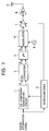
- Fig. 1 shows a basic structure of a transmitting circuit of a communication device for a mobile unit according to a TDMA system (Time Division Multiple Access system).
- an I-Q component generating circuit 1 converts a digital information signal to be transmitted into a quadrature component Q and an in-phase component I and outputs them in accordance with the digital phase modulation of a ⁇ /4 shift DQPSK method.
- the operation of the I-Q component generating circuit 1 is controlled by a microcomputer 2.
- a D/A converter 3 is connected to an output of the I-Q component generating circuit 1.
- the D/A converter 3 changes the transferred symbol data of I and Q channels to corresponding analog data and supplies it to an LPF 4.
- the LPF 4 passes only a given low-frequency band of an input signal, in other words, the LPF 4 removes a higher harmonic component thereof, and supplies it to a modulator 5.
- the modulator 5 is of, for example, a Costas type, and performs a modulation of the ⁇ /4 shift DQPSK method while treating the output signal of the LPF 4 as a signal to be transmitted on the basis of an oscillating output signal of a local oscillator 6.
- the oscillating output signal of the local oscillator 6 has a predetermined carrier frequency in the communication device concerned, and this becomes the central frequency in that modulation.
- a transmission signal that is a modulation output of the modulator 5 is supplied to a power amplifier 8 through a variable gain amplifier 7.
- the variable gain amplifier 7 is disposed as a pre-amplifier of the power amplifier 8, and an amplification gain is controlled by the microcomputer 2.
- the power amplifier 8 further amplifies the transmission signal amplified by the variable gain amplifier 7, and applies it to an antenna 9, and, as a result, the transmission signal is radiated from the antenna 9 in the form of transmission waves.
- a TDMA transmission signal transmitted along the time series (T) performs a downward communication (from a base station to a moving apparatus) and an upward communication (from the moving apparatus to the base station) per frame.
- One channel is allocated by a pair of time zones, i.e., slots (transmission block) that have been allocated to each communication period in the TDMA frame.
- Fig. 2 shows a case where two channels (two slots in. each of the down and up) exist in one frame. For example, in slot number 1, data A is transmitted during the downward communication, and data B is transmitted during the upward communication, as shown in the figure.
- the transmitting circuit of the base station transmits (or, receives) data A, and receives (or, transmits) data B in the time zone indicated by slot number 1.
- the channel can be subdivided into a control channel and a communication channel.
- the control channel is to be used in communication for setting the communication channel, and in practice, the communication channel is to transmit information for performing communication, such as a conversation on the telephone.
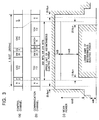
- the slot of the control channel has a structure shown in (a) of Fig. 3, for example, and the slot of the communication channel has a structure shown in (b) of Fig. 3, for example.
- G designates a guard time
- P designates a preamble (i.e., bit necessary for bit synchronization)
- R designates a lamp time part (burst transient response bit)
- SW designates a sync-word (bit necessary for frame synchronization)
- CAC designates a common access channel for radio system control
- TCH designates a traffic channel that carries information
- SACCH designates an associated control channel that is associated with TCH.
- the guard time G is provided so that the waveforms of adjoining slots never overlap with each other because of, for example, a synchronous deviation.
- the traffic channel TCH and the associated control channel SACCH are transmission information
- the preamble P and the sync-word SW are control data necessary for synchronous capture.
- the numerical values in (a) and (b) of Fig. 3 designate bit number.
- RCR STD-27 which is the specification of PDC (Personal Digital Cellular) prescribes that the envelope waveform of the output signal of the power amplifier 8 with respect to the slot is only required to change within the range between the upper and lower limits shown by the oblique lines in (c) of Fig. 3.
- the mean power is 29 dBm, and its accuracy is +20%, and -50%.
- the microcomputer 2 controls the gain of the variable gain amplifier 7 according to items in the slot to be transmitted. Next, the gain control will be described with reference to a flowchart.
- the microcomputer 2 determines whether the item to be transmitted is a preamble P or not (step S1). If it is a preamble P corresponding to a control data portion, the gain of the variable gain amplifier 7 is set at a first predetermined value (step S2). If it is not a preamble P, the microcomputer 2 determines whether the item to be transmitted is a sync-word SW or not (step 53). If it is a sync-word SW corresponding to a control data portion, the stage proceeds to step S2, and the gain of the variable gain amplifier 7 is set at the first predetermined value. If it is not a sync-word SW, the microcomputer 2 determines whether the item to be transmitted is one of the other items or not (step S4).
- the other items are a transmission information portion, such as the traffic channel TCH, and a control data portion, such as the associated control channel ACCH, excluding a preamble P, sync-word SW, and guard time G. If it is the other item, the gain of the variable gain amplifier 7 is set at a second predetermined value that is smaller than the first predetermined value (step S5).
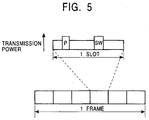
- the transmission power by the power amplifier 8 becomes higher during a period corresponding to each of the preamble P and the sync-word SW than during the other periods in the slot.
- the envelope waveform of this transmission signal is included within the range between the upper and lower limits shown in (c) of Fig. 3.
- the preamble P and the sync-word SW of each slot are indispensable because the preamble P takes bit synchronization at the receiving side and because the sync-word SW takes frame synchronization at the receiving side. Accordingly, if the envelope waveform of the output signal of the power amplifier 8 during periods corresponding to the preamble P and the sync-word SW is heightened more than during the other periods, the synchronous capture per slot will be easily and steadily carried out at the receiving side. Additionally, several bits following the preamble P are needed besides the preamble P in order to capture the stable bit synchronization, and therefore those bits may be arranged so as to set the gain of the variable gain amplifier 7 at the first predetermined value.
- the envelope waveform of the output signal of the power amplifier 8 is heightened during the periods corresponding to the preamble P and the sync-word SW more than during the other periods.
- the period corresponding to the preamble P and the period corresponding to the sync-word SW do not need to have the same transmission power. What is needed is for it to be heightened more than during the other periods.
- the transmission power is changed by the gain control of the variable gain amplifier 7 in the slot.
- the transmission power may be changed in the slot by controlling the applied voltage of a negative voltage power supply 11 onto the power amplifier 8 by means of the microcomputer 2, as shown in Fig. 6.
- information necessary for the bit synchronization and the frame synchronization is described as an example. However, without being limited to this, other information may be used if it is a synchronizing signal needed when a transmission block, such as a slot, is received.
- the phrase "when a transmission block is received” means "when a transmission block is received by a relay station, a base station, or the communication device itself for a mobile unit.”
- the transmission level may be raised by extracting peripheral information including the information necessary for synchronization in this case.
- the present invention may be applied to a transmitting circuit of the type that has transmission information and information necessary for various synchronizations in a slot.
- a transmitting circuit of the CDMA system Code Division Multiple Access system
- each of a plurality of consecutive frames, as shown in (a) of Fig. 7 is provided with slots having different transmission powers, as shown in (b) of Fig. 7.
- an arrangement may be made to raise the transmission level of information necessary for the synchronous capture when the slot is received.
- the signal level of the transmission signal is described as a structure to be always adjusted.
- the present invention may be made according to the receiving status. For example, a judgment may be made about whether the receiving status is good or not in accordance with the error percentage of a received signal or the receiving level thereof. If good, the processing of the present invention is carried out, and, if not, the processing thereof is not carried out.
- the transmission power of a part necessary for synchronization is increased at the receiving side, and therefore it is possible to save electric power without inviting a deterioration in communication performance.
Landscapes
- Engineering & Computer Science (AREA)
- Computer Networks & Wireless Communication (AREA)
- Signal Processing (AREA)
- Mobile Radio Communication Systems (AREA)
- Transmitters (AREA)
Abstract
Description
Claims (9)
- A communication device for a mobile unit for performing radio communication in frames having a plurality of transmission blocks each of which comprises a transmission information portion and a control data portion relative to the transmission information portion, the communication device for a mobile unit comprising:a modulating part which modulates said frames according to a predetermined modulation scheme and genertes a modulated output signal; anda transmission level adjusting part which receives said modulated output signal of said modulating part and adjusts transmission levels of said transmission information portion and said control data portion in said modulated output signal respectively so that said transmission levels differ from each other.
- The communication device for a mobile unit as claimed in claim 1, wherein said transmission level adjusting part adjusts the transmission level of said control data portion to be higher than the transmission level of said transmission information portion.
- The communication device according to Claim 1, wherein the transmission level adjusting part performs an adjustment so that a transmission level of a part in said control data portion necessary for capturing synchronization when said transmission block is received becomes higher than the transmission level of said transmission information portion.
- The communication device according to Claim 2, wherein the transmission level adjusting part performs an adjustment so that a transmission level of a part in said control data portion necessary for capturing synchronization when said transmission block is received becomes higher than the transmission level of said transmission information portion.
- A communication device for a mobile unit for performing radio communication in frames capable of constructing a plurality of transmission blocks each of which comprises digital data having transmission information in one part thereof, comprising:a modulating part which modulates said frames according to a predetermined modulation scheme and generates a modulated output signal; anda transmission level adjusting part which receives said modulated output signal of said modulating part and performs an adjustment so that a transmission level of the digital data necessary for a bit synchronization capture when said transmission blocks are received becomes higher than a transmission level of said transmission information.
- The communication device for a mobile unit as claimed in claim 1, wherein said transmission level adjusting part changes the transmission level in said transmission block.
- The communication device for a mobile unit as claimed in claim 5, wherein said transmission level adjusting part changes the transmission level in said transmission block.
- The communication device for a mobile unit as claimed in claim 1, wherein said transmission level adjusting part comprises a variable gain amplifier before a power amplifier of a transmitting circuit and a control part for changing the gain of said variable gain amplifier in accordance with each of said transmission information portion to be transmitted and said control data portion to be transmitted.
- The communication device for a mobile unit of Claim 1, wherein said transmission level adjusting part comprises a variable power supply for supplying a voltage to a bias adjusting terminal of a power amplifier of a transmitting circuit and a control part for changing a voltage from said variable power supply to the power amplifier in accordance with each of said transmission information portion to be transmitted and said control data portion to be transmitted.
Applications Claiming Priority (2)
| Application Number | Priority Date | Filing Date | Title |
|---|---|---|---|
| JP2000091735A JP2001285087A (en) | 2000-03-29 | 2000-03-29 | Mobile communications equipment |
| JP2000091735 | 2000-03-29 |
Publications (2)
| Publication Number | Publication Date |
|---|---|
| EP1146654A2 true EP1146654A2 (en) | 2001-10-17 |
| EP1146654A3 EP1146654A3 (en) | 2003-10-15 |
Family
ID=18607164
Family Applications (1)
| Application Number | Title | Priority Date | Filing Date |
|---|---|---|---|
| EP01107400A Withdrawn EP1146654A3 (en) | 2000-03-29 | 2001-03-26 | Communication device for mobile unit |
Country Status (3)
| Country | Link |
|---|---|
| US (1) | US20010036815A1 (en) |
| EP (1) | EP1146654A3 (en) |
| JP (1) | JP2001285087A (en) |
Families Citing this family (2)
| Publication number | Priority date | Publication date | Assignee | Title |
|---|---|---|---|---|
| US7310381B2 (en) * | 2003-06-16 | 2007-12-18 | Intel Corporation | Power amplifier pre-distortion device and method for orthogonal frequency division multiplexing |
| JP7058694B2 (en) * | 2020-08-20 | 2022-04-22 | 三菱電機株式会社 | Base station equipment and terminal wireless equipment |
Family Cites Families (4)
| Publication number | Priority date | Publication date | Assignee | Title |
|---|---|---|---|---|
| JPH1079701A (en) * | 1996-09-03 | 1998-03-24 | Fujitsu Ltd | Mobile communication terminal and transmission power control method thereof |
| FI965104L (en) * | 1996-12-18 | 1998-06-19 | Nokia Telecommunications Oy | Method for improving system capacity in a cellular radio system and base station |
| RU2222117C2 (en) * | 1998-04-08 | 2004-01-20 | Нокиа Мобайл Фоунс Лтд | Method and system for controlling transmission power of separate radio transmission parts |
| US6173163B1 (en) * | 1998-06-30 | 2001-01-09 | Ericsson Inc. | Switched sampling systems and methods for monitoring radio transmit power |
-
2000
- 2000-03-29 JP JP2000091735A patent/JP2001285087A/en active Pending
-
2001
- 2001-03-26 EP EP01107400A patent/EP1146654A3/en not_active Withdrawn
- 2001-03-29 US US09/820,278 patent/US20010036815A1/en not_active Abandoned
Also Published As
| Publication number | Publication date |
|---|---|
| US20010036815A1 (en) | 2001-11-01 |
| JP2001285087A (en) | 2001-10-12 |
| EP1146654A3 (en) | 2003-10-15 |
Similar Documents
| Publication | Publication Date | Title |
|---|---|---|
| KR100701913B1 (en) | Continuous Closed Loop Power Control System Including Modulation Injection into Wireless Transceiver Power Amplifier | |
| KR100789203B1 (en) | A computer readable recording medium having recorded thereon a method, a system for controlling output power from an amplifier using a closed power control feedback loop, and a program for implementing it in a computer | |
| RU2121755C1 (en) | Power amplifier combined with amplitude- and phase-modulation controllers | |
| EP1107449B1 (en) | Non-linear distortion compensation circuit, transmitter device to be employed in the same and mobile communication unit | |
| US5933767A (en) | Apparatus and method for tuning the gain of a transmitter utilizing cartesian feedback | |
| US7342955B2 (en) | Apparatus and method for mobile communication device transmission | |
| US7061888B2 (en) | Communication method and apparatus in which a total power of power control information is a fixed valued | |
| US7171168B2 (en) | Ramp signal with boost portion preceding a time slot | |
| US5613226A (en) | Linear transmitter for use in combination with radio communication systems | |
| KR100983174B1 (en) | Method and apparatus for controlling spurious transmissions in a communication system | |
| EP1146654A2 (en) | Communication device for mobile unit | |
| US20030228854A1 (en) | Method and system for increasing the output power of a wireless signal | |
| EP0765042A2 (en) | A time-division radio that induces reduced baseband interference | |
| EP1422837B1 (en) | Automatic control apparatus and method for TD-SCDMA mobile terminal | |
| US5864586A (en) | Radio apparatus with offset compensating circuit | |
| US8433361B2 (en) | Digital modulator and method for initiating ramp power transitions in a mobile handset transmitter | |
| US20040198266A1 (en) | Control circuitry | |
| KR100581268B1 (en) | Apparatus and method for radio transmitter | |
| JP3951046B2 (en) | Transmission level control device | |
| KR960011124B1 (en) | Tdma | |
| KR100234830B1 (en) | A method for direct frequency modulation and a circuit for oscillating if using the mixer | |
| JP2004134913A (en) | Transmission device and communication device | |
| JPH0998109A (en) | Communication device | |
| JPH07123065A (en) | Time division multiple access wireless device | |
| JPH10233714A (en) | Spread spectrum wireless communication equipment |
Legal Events
| Date | Code | Title | Description |
|---|---|---|---|
| PUAI | Public reference made under article 153(3) epc to a published international application that has entered the european phase |
Free format text: ORIGINAL CODE: 0009012 |
|
| AK | Designated contracting states |
Kind code of ref document: A2 Designated state(s): AT BE CH CY DE DK ES FI FR GB GR IE IT LI LU MC NL PT SE TR |
|
| AX | Request for extension of the european patent |
Free format text: AL;LT;LV;MK;RO;SI |
|
| PUAL | Search report despatched |
Free format text: ORIGINAL CODE: 0009013 |
|
| AK | Designated contracting states |
Kind code of ref document: A3 Designated state(s): AT BE CH CY DE DK ES FI FR GB GR IE IT LI LU MC NL PT SE TR |
|
| AX | Request for extension of the european patent |
Extension state: AL LT LV MK RO SI |
|
| RIC1 | Information provided on ipc code assigned before grant |
Ipc: 7H 04J 3/06 B Ipc: 7H 04B 7/26 B Ipc: 7H 04B 1/40 B Ipc: 7H 04B 1/16 A |
|
| 17P | Request for examination filed |
Effective date: 20031223 |
|
| 17Q | First examination report despatched |
Effective date: 20040331 |
|
| AKX | Designation fees paid |
Designated state(s): DE FR GB |
|
| STAA | Information on the status of an ep patent application or granted ep patent |
Free format text: STATUS: THE APPLICATION IS DEEMED TO BE WITHDRAWN |
|
| 18D | Application deemed to be withdrawn |
Effective date: 20041012 |