EP1146653A2 - Power saving in mobile stations - Google Patents
Power saving in mobile stations Download PDFInfo
- Publication number
- EP1146653A2 EP1146653A2 EP01101593A EP01101593A EP1146653A2 EP 1146653 A2 EP1146653 A2 EP 1146653A2 EP 01101593 A EP01101593 A EP 01101593A EP 01101593 A EP01101593 A EP 01101593A EP 1146653 A2 EP1146653 A2 EP 1146653A2
- Authority
- EP
- European Patent Office
- Prior art keywords
- mobile station
- demodulator
- assigned channel
- stationary
- measuring
- Prior art date
- Legal status (The legal status is an assumption and is not a legal conclusion. Google has not performed a legal analysis and makes no representation as to the accuracy of the status listed.)
- Granted
Links
- 238000000034 method Methods 0.000 claims abstract description 41
- 230000000694 effects Effects 0.000 claims abstract description 22
- 230000033001 locomotion Effects 0.000 claims description 55
- 238000005259 measurement Methods 0.000 claims description 42
- 230000001413 cellular effect Effects 0.000 description 14
- 230000005540 biological transmission Effects 0.000 description 8
- 230000008859 change Effects 0.000 description 5
- 230000009467 reduction Effects 0.000 description 5
- 230000001360 synchronised effect Effects 0.000 description 5
- 238000012545 processing Methods 0.000 description 4
- 230000001133 acceleration Effects 0.000 description 3
- 238000004364 calculation method Methods 0.000 description 3
- 230000006870 function Effects 0.000 description 3
- 230000015654 memory Effects 0.000 description 3
- 238000012544 monitoring process Methods 0.000 description 3
- 230000011664 signaling Effects 0.000 description 3
- 108010003272 Hyaluronate lyase Proteins 0.000 description 2
- 230000009849 deactivation Effects 0.000 description 2
- 230000003111 delayed effect Effects 0.000 description 2
- 238000001914 filtration Methods 0.000 description 2
- 230000010363 phase shift Effects 0.000 description 2
- 230000008569 process Effects 0.000 description 2
- 238000010187 selection method Methods 0.000 description 2
- 230000035945 sensitivity Effects 0.000 description 2
- 238000004458 analytical method Methods 0.000 description 1
- 230000008901 benefit Effects 0.000 description 1
- 230000000295 complement effect Effects 0.000 description 1
- 238000004590 computer program Methods 0.000 description 1
- 238000012937 correction Methods 0.000 description 1
- PCHJSUWPFVWCPO-UHFFFAOYSA-N gold Chemical compound [Au] PCHJSUWPFVWCPO-UHFFFAOYSA-N 0.000 description 1
- 239000010931 gold Substances 0.000 description 1
- 229910052737 gold Inorganic materials 0.000 description 1
- 230000000977 initiatory effect Effects 0.000 description 1
- 230000007257 malfunction Effects 0.000 description 1
- 238000007726 management method Methods 0.000 description 1
- 238000013507 mapping Methods 0.000 description 1
- 239000003550 marker Substances 0.000 description 1
- 230000007246 mechanism Effects 0.000 description 1
- 229910044991 metal oxide Inorganic materials 0.000 description 1
- 150000004706 metal oxides Chemical class 0.000 description 1
- 230000000737 periodic effect Effects 0.000 description 1
- 230000007420 reactivation Effects 0.000 description 1
- 238000013468 resource allocation Methods 0.000 description 1
- 239000004065 semiconductor Substances 0.000 description 1
- 238000000926 separation method Methods 0.000 description 1
- 230000003595 spectral effect Effects 0.000 description 1
- 238000001228 spectrum Methods 0.000 description 1
- 230000007480 spreading Effects 0.000 description 1
- 230000003068 static effect Effects 0.000 description 1
- 230000036962 time dependent Effects 0.000 description 1
Images



Classifications
-
- H—ELECTRICITY
- H04—ELECTRIC COMMUNICATION TECHNIQUE
- H04B—TRANSMISSION
- H04B1/00—Details of transmission systems, not covered by a single one of groups H04B3/00 - H04B13/00; Details of transmission systems not characterised by the medium used for transmission
- H04B1/69—Spread spectrum techniques
- H04B1/707—Spread spectrum techniques using direct sequence modulation
- H04B1/7097—Interference-related aspects
- H04B1/711—Interference-related aspects the interference being multi-path interference
- H04B1/7115—Constructive combining of multi-path signals, i.e. RAKE receivers
-
- H—ELECTRICITY
- H04—ELECTRIC COMMUNICATION TECHNIQUE
- H04B—TRANSMISSION
- H04B1/00—Details of transmission systems, not covered by a single one of groups H04B3/00 - H04B13/00; Details of transmission systems not characterised by the medium used for transmission
- H04B1/69—Spread spectrum techniques
- H04B1/707—Spread spectrum techniques using direct sequence modulation
- H04B1/7097—Interference-related aspects
- H04B1/711—Interference-related aspects the interference being multi-path interference
- H04B1/7115—Constructive combining of multi-path signals, i.e. RAKE receivers
- H04B1/7117—Selection, re-selection, allocation or re-allocation of paths to fingers, e.g. timing offset control of allocated fingers
-
- H—ELECTRICITY
- H04—ELECTRIC COMMUNICATION TECHNIQUE
- H04B—TRANSMISSION
- H04B2201/00—Indexing scheme relating to details of transmission systems not covered by a single group of H04B3/00 - H04B13/00
- H04B2201/69—Orthogonal indexing scheme relating to spread spectrum techniques in general
- H04B2201/707—Orthogonal indexing scheme relating to spread spectrum techniques in general relating to direct sequence modulation
- H04B2201/70707—Efficiency-related aspects
Definitions
- This invention relates to mobile stations such as radiotelephones and in particular to mobile transceivers or user equipment capable of operating in a cellular radio network.
- the invention also relates to a power saving method to prolong battery life.
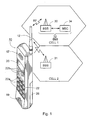
- FIG. 1 illustrates a cellular radio system comprising a number of base station sub-systems (BSSs) 30 and 31.
- Each base station sub-system comprises a base station (BS) and a base station controller (BSC).
- the base stations offer a two way radio interface to a mobile station 10 as defined by specifications of the cellular radio system.
- Such a radio interface comprises a plurality of defined channels, the exact arrangement and usage of which is specific to each cellular radio system.
- An example of one prior art system is the Global System for Mobile telecommunications (GSM) system.
- GSM Global System for Mobile telecommunications
- the radio interface offered to mobile stations in cells such as cell 1 and cell 2 consists of a number of common channels and a number of dedicated channels.
- a cellular radio system is often referred to as a "network” although the overall network comprises the Public Land Mobile Network (PLMN) section and a gateway connection to different public networks such as Public Switched Telecommunication Networks (PSTNs) referred to as “fixed networks”.
- PLMN Public Land Mobile Network
- PSTNs Public Switched Telecommunication Networks
- the mobile station 10 requesting service from the network when initiating a call initiates a signalling message on an uplink radio interface channel called RACH (Random Access Channel) via a common uplink channel.
- RACH Random Access Channel
- the initiated access request is received at a base station from where it is forwarded to the respective BSC.
- the access request is forwarded further to a Mobile Switching Center (MSC) 34 that is in charge of the procedures concerning call control.
- MSC 34 acknowledges the access request to the mobile station via the BBS and a dedicated connection from the mobile station to the MSC can be established by assigning necessary connection resources as required between the mobile station 10 and the MSC 34.
- connection is made from an external network connection support mechanism of the MSC referred to as a gateway MSC.
- the gateway MSC is usually integrated into the MSC 34.
- a call connection may then be made to national or international networks depending on the number which has been dialled.
- the mobile station 10 After the mobile station 10 has been switched on, it takes a short time period until it is fully operational.
- the mobile terminal 10 first acquires synchronisation in a certain cell and then starts to listen to general information which is broadcast in the network in a downlink direction. A suitable cell is selected on the basis of received signal strength and additional criteria. After having selected a cell the mobile station 10 initiates a location update to the selected cell. Finally the mobile station 10 settles down in the selected cell waiting for a paging message.
- a mobile station has at least two basic functional states when it is switched on: an idle mode and an active dedicated mode.
- an idle mode When the mobile station is on, but no call is activated, answered or no data connection is established, the mobile station is in its idle mode. Thus it is able, for example, to be paged for terminating calls and terminating short messages and the user may initiate a call or other service requests.
- the dedicated mode of the mobile station occurs when a dedicated connection or logical link of packet radio link is seized or initiated to be reserved.
- the state change from idle mode to dedicated mode can be identified by the mobile station requesting resource allocation of dedicated resources of air interface connections. The mobile station will change from the dedicated mode to the idle mode when connection release has taken place.
- GSM systems operate according to time division multiple access (TDMA).
- TDMA time division multiple access
- co-located cells use different pilot frequencies and a receiver is tuned to listen.
- a mobile station measures each frequency of neighbouring cells in order to be using the most suitable available cell.
- the mobile station may request and be granted a certain set of transmission circuits which may be a particular time slot or a set of time slots.
- the bandwidth carried by the pilot frequency of TDMA is divided in time into eight timeslots.
- EP 812 119 concerns a GSM system and discloses a method for operating a cellular telephone in standby mode.
- the method involves the cellular telephone measuring the currently assigned channel and at least one other currently non-assigned channel.
- the cellular telephone detects changes in the received signal strength indicator (RSSI), in bit error rate (BER) or in similar parameter measurements, to determine whether or not it is stationary.
- RSSI received signal strength indicator
- BER bit error rate
- the cellular telephone terminates the measurements of at least one of the currently non-assigned channels to conserve energy, but continues monitoring the error rate to determine when it starts moving again.
- the method allows battery power of a cellular telephone to be saved by avoiding measurements for handoff when the cellular telephone is stationary.
- the prior art also proposes mobile stations determining whether they are stationary by using an acceleration transducer to analyse motion in respect a random motion vector.
- UMTS universal mobile telecommunications system
- An UMTS system is similar in basic configuration to the system of Figure 1 and comprises mobile stations (referred to as user equipment (UE)) connected to a mobile network.
- UE user equipment
- UTRA the terrestrial radio network access section
- DS-CDMA Direct-Sequence CDMA
- WCDMA Wideband CDMA
- UTRA has two functional modes, FDD (Frequency Division Duplex) and TDD (Time Division Duplex), for operating with paired and unpaired radio frequency bands respectively.
- FDD Frequency Division Duplex
- TDD Time Division Duplex
- the ability of a mobile station to operate in either FDD or TDD mode allows for efficient utilisation of the available spectrum according to the frequency allocation in different regions.
- TS 25.201 Physical layer -General description of the Third Generation Partnership Project (3GPP).
- the radio access network RAN definition of TDD is presented in technical specification TS 25.102.
- the FDD RAN is specified in technical specification TS 25.101.
- FDD comprises a duplex method in which uplink and downlink transmissions use two different radio frequency bands.
- a pair of radio frequency bands, which have a specified separation, are assigned for the system.
- TDD comprises a duplex method in which uplink and downlink transmissions are carried over the same radio frequency by using synchronised time intervals.
- time slots in a physical channel are divided into a transmission and a reception part.
- Information is transmitted reciprocally on uplink and downlink between the mobile station and the radio access network (RAN).
- RAN radio access network
- TDMA component in air interface multiple access in addition to DS-CDMA.
- the multiple access has been also often denoted as TDMA/CDMA.
- a 10 ms radio frame is divided into 15 slots (2560 chip/slot at a chip rate of 3.84 Mcps (Mega-chips per second)).
- a chip is a signal pulse cycle that is transferred by a transceiver to air interface and received by the receiver.
- a physical channel is defined as a code (or number of codes) and particular sequence of time slots.
- the information rate of the channel varies with the symbol rate being derived from the 3.84 Mcps chip rate and the spreading factor.
- the modulation symbol rates for FDD vary from 960 k symbols/s to 15 k symbols/s for uplink and from 960 k symbols to 7.5 k symbols/s for downlink.
- the modulation symbol rates vary from 3.84 M symbols/s to 240 k symbols/s.
- Opportunity Driven Multiple Access (ODMA) in TDD mode can be used for relaying between nodes.
- ODMA Opportunity Driven Multiple Access
- channel coding and interleaving in UTRA has three optional alternatives, which are convolution coding, turbo-coding or no-channel coding.
- Upper layers of the network for the physical radio network indicate the channel coding selection.
- the radio network and cells have a hierarchical structure in which neighbouring cells in a cell layer use the same pilot frequency and in dedicated mode the radio link connections between the base station and the mobile station are uniquely identified by using codes to enable call identification.
- a modulation arrangement will now be described with reference to Figure 4.
- a receiver of a mobile station uses a correlator 61 in its RF section to despread a desired signal which then is passed through a baseband filter pass 62 in order to extract the desired signal.
- the desired signal is then passed on to a baseband section.
- Initial synchronisation of the receiver code to the RF carrier needs to be achieved before despreading may be processed.
- the demodulation techniques used in receivers of mobile stations can be frequency-shift keying (FSK), phase-shift keying (PSK) or others.
- FSK frequency-shift keying
- PSK phase-shift keying
- QPSK quadrature phase-shift keying
- the final demodulation is processed in a rake receiver which is described in the following.
- Radio systems suffer from multipath propagation in which signals arrive at a receiver from a number of paths of different lengths. This leads to a summation of randomly phased signals that may cause interference.
- CDMA systems having high chip rate digital signals it is possible to obtain a benefit of multipath propagation by using time diversity. This is done by using a rake receiver.
- FIG. 6 shows a mobile station used in a WCDMA system.
- the mobile station comprises conventional features such as an RF block 42, a deinterleaver 48, a channel decoder 49, a data buffer 81, a speech decoder 50 and a speaker 51. These features are well known and they will not be described since they are not directly relevant to the following description.
- the mobile station also has a rake receiver 90 located between the RF block 42 and the deinterleaver 48.
- the rake receiver 90 comprises a number of correlator receivers, or demodulator fingers, which typically use the same code, whose operations are displaced relative to each other by increasing time intervals of the chip interval.
- the rake receiver 90 also comprises a matched filter 74 which is used for filtering the output of the RF block 42.
- each signalling or traffic channel carries its own pilot signal (a channel associated pilot signal). Because the pilot signal is not continuous, a synchronisation marker is transmitted to enable the rake receiver 90 to find the pilot signal.
- output of the correlator 61 is transformed from a wideband signal into a narrow band signal of the information bearing a carrier which passes through the narrow inter frequency IF band filter (in Figure 6 matched filter 74).
- a control signal is generated to set the receiver's clock at its nominal rate so as to track the incoming signal.
- a short code with high repetition rate is used to gain synchronisation.
- the power of the pilot is lower relative to noise than would be the case for a common pilot signal.
- By having periodic transmission of a very short known code sequence and having a fixed time alignment with the pilot signal gives necessary pre-alignment with the pilot sequence before despreading.
- the occurrence of a code having good autocorrelation properties will produce a short duration spike at the output of the matched filter 74.
- Those spikes act as markers for time alignment with each incoming signal. Different incoming signals producing a spike may be time dispersed paths from the serving cell or neighbouring cells.
- the synchronisation achieved must be maintained by running the receiver's clock at a rate exactly the same as the incoming signal rate.
- Delay clock tracking is used having two identical codes generated by a code generator 84 in the receiver one being one chip interval behind the other.
- the delayed and non-delayed signals are equalised in an equaliser 83.
- Output of the two correlators is summed in a combiner 78.
- I- and Q-branches are independently multiplied with an Orthogonal Variable Spreading Factor (OVSF) code.
- OVSF Orthogonal Variable Spreading Factor
- the resultant signals on the I- and Q-branches are further multiplied by complex-valued scrambling code, where I and Q denote real and imaginary parts, respectively.
- the rake receiver also comprises a searcher 76.
- the searcher 76 configures the demodulator fingers to monitor specific radio frequencies and downlink channels that can be configured to receive signals from different downlink radio bearers from BSSs of the WCDMA RAN. Parallel downlink demodulation enables the mobile station to receive signals from multipaths as explained above.
- the searcher 76 is in charge of initial synchronisation to be accomplished in downlink.
- the searcher 76 also controls all procedures the receiver does concerning the mobility management procedures known as cell re-selection and handover. Cell re-selection and handover refer to the mobile station being located and served by the most suitable base station of the RAN. According to channel measurements and possibly some other criteria the searcher 76 re-configures the demodulator fingers to listen to downlink of a new base station as specified in technical specifications TS 25.304 and TS 25.305.
- a method of operating a mobile station comprising the steps of:
- the mobile station comprises a rake receiver.
- the rake receiver may comprise a plurality of demodulator fingers each of which is used to receive time diversified signals.
- the mobile station comprises a searcher. The searcher may be used for synchronising the time diversified signals.
- the method comprises the step of measuring at least one non-assigned channel.
- the non-assigned channel may be measured by a demodulator finger of the rake receiver. This demodulator finger may be allocated for monitoring neighbouring, non-assigned, cells. It may be dedicated to this task.
- a currently non-assigned channel is measured by a demodulator finger which is also used for assigned channel reception. Measurement of the currently non-assigned channel or channels may occur during the idle mode for that demodulator finger.
- Preferably reducing the activity occurs by deactivating the parts of the demodulator which are concerned with measuring the non-assigned channel. This may be at least one of the plurality of demodulator fingers. Alternatively it occurs by slowing down idle mode processing of the demodulator. That is, processing of idle mode frames carrying system information which are transmitted by base stations are processed by the mobile station less frequently. This may occur by processing only alternate frames or skipping more than every other frame.
- reducing the activity of the demodulator involves disconnecting a voltage supply to one or more demodulator fingers. Alternatively it involves preventing signal state changes in the demodulator fingers. This may occur by disconnecting a timing signal to at least one of the demodulator fingers. This is particularly suitable if the demodulator fingers comprise CMOS circuitry.
- the non-assigned channel being measured less frequently is the common control physical channel CCPCH.
- the non-assigned channel being measured less frequently may be the common primary pilot channel CPICH.
- Detecting whether the mobile station is stationary may be done in several ways.
- a motion detector is integrated in the mobile station. It may be done by detecting changes in power level or in other downlink measurement parameters in a received signal.
- the step of determining whether the mobile station is stationary involves calculation of a motion indicator.
- the motion indicator may be calculated at specified time intervals. Preferably it is calculated based on one or more parameters selected from a group consisting of: RSSI of a serving cell, RSSI of a neighbouring cell, signal-to-interface ratio (SIR) of a serving cell, SIR of a neighbouring cell, received signal code power (RSCP) of a serving cell, RSCP of a neighbouring cell, block error rate (BLER) of a serving cell, BLER of a neighbouring cell, BER of a serving cell and BER of a neighbouring cell.
- SIR signal-to-interface ratio
- RSCP received signal code power
- BLER block error rate
- a combined motion indicator is calculated comprising a sum of measured parameters. Preferably it is a weighted sum of measured parameters.
- the motion indicator is compared with a threshold value to determine whether the mobile station is stationary.
- an average value of the combined motion indicator or a weighted average value of the combined motion indicator is compared with a threshold value. Motion is determined if the motion indicator exceeds the threshold value.
- the processing rate of searcher activity of the rake receiver is reduced.
- This step may be in addition to deactivating a demodulator finger.
- a mobile station comprising a receiver having a radio frequency block and a demodulator, means for putting the mobile station into an idle mode, means for measuring a currently assigned channel, a motion indicator for detecting if the mobile station is stationary and an activity controller for reducing the activity of the demodulator if the mobile station is stationary.
- the mobile station comprises means for measuring at least one currently non-assigned channel.
- a telecommuncations system operating according to the first aspect of the invention or comprising a mobile station according to the second aspect of the invention.
- the mobile station is for use in a CDMA system. Preferably it is for use in a WCDMA system.
- the mobile station may be used in a third generation mobile system, for example the UTRA system.
- the receiver circuitry of the mobile station comprises a number of correlator receivers using the same code but displaced by increasing time intervals of the chip interval.
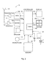
- FIG. 2 shows a WCDMA mobile station 10.
- the mobile station 10 comprises an antenna unit 12 for transmitting and receiving signals between itself and BSSs of a RAN of a universal terrestrial radio access network (UTRAN).
- the RAN of the UTRAN is connected to a core network (CN) of a universal mobile telecommunication system (UMTS) and comprises a mobile switching center (MSC) that provides connection from the RAN to other networks.
- CN core network
- UMTS universal mobile telecommunication system
- MSC mobile switching center
- Individual base stations of the RAN have radio coverage areas defining a cells which are typically adjacent, for example cell 1 and cell 2 in Figure 1.
- the mobile station 10 (user equipment) comprises a modulator MOD 14A, a transmitter 14, a receiver 16, a demodulator DEMOD 16 A and a controller 18 which provides signals to and receives signals from the transmitter 14 and the receiver 16 respectively. These signals include signalling information in accordance with air interface specifications of applicable cellular systems specifications and user payload such as speech and data.
- the air interface specification of the UTRAN is specified in technical specification TS 25.304.
- the UTRAN has FDD and TDD mode air interface connections which are measured at least for channel re-selection purposes.
- the measured channels are a common control physical channel CCPCH in TDD mode and a common primary pilot channel CPICH in FDD mode.
- a plurality of cells provides good coverage over a wide area.
- the mobile station 10 measures the received signal strength indicator (RSSI) of the currently used BSS as well as the best neighbouring cells.
- the mobile station also measures bit error ratio (BER), block error rate (BLER), signal to interference ratio (SIR) and received signal code power (RSCP).
- BER bit error ratio
- BLER block error rate
- SIR signal to interference ratio
- RSCP received signal code power
- the mobile station comprises an earphone or a speaker 17, a microphone 19, a display 20, and a user input device, typically a keypad 22, all of which are coupled to the controller 18.
- the keypad 22 includes conventional numerical (0 to 9) and additional related keys 22a, for example a SEND key and an END key, used for operating the mobile station 10.
- the mobile station 10 also includes several memories, shown as single memory block 24, in which constants and variables used for control operation are stored. An operating program is stored in the memory block 24. It may contain other matters such as user messages.
- a battery 26 powers the mobile station 10.
- the mobile station 10 also comprises means to determine whether it is stationary.
- Figure 3 shows the major blocks in the downlink, receiver, path of the WCDMA mobile station.
- a signal is received by an antenna unit 42 and passed on to a power amplifier, filtering and scrambling section 46.
- the signal is then demodulated in a demodulator 47.
- the demodulated signal is passed to a deinterleaving block 48 which re-orders all the bits that were distributed and ordered according to the modulation scheme of the radio link of the system. Ordering is originally carried out in order to provide a more error burst tolerant transmission.
- a channel decoder 49 carries out correction.
- the signal is decompressed in a speech decoder unit 50 according to applied speech coding methods, and the resultant digitised speech is used to drive an audio speaker unit 51.
- the mobile station When it is switched on, the mobile station carries out a cell search as soon as all the receiver circuitry has settled into a power on state and all its necessary basic configuration settings have been carried out so that it is functioning normally.
- the cell search (controlled by the searcher 76) the mobile station detects a downlink transmission of a cell, and then the scrambling code and frame synchronisation of the cell is handled.
- the primary scrambling code is identified, the primary common control physical channel (PCCPCH) is detected, and super-frame synchronisation can then be acquired so that the system and cell specific broadcast channel (BCH) information can be read.
- the BCH carries all cell specific information of the physical link layer itself like timing offset information of the secondary common control physical channel (SCCPCH) against the PCCPCH as well as other information like service support of the cell to the mobile stations capable of listening to it. If the mobile station has received a priority list with information about which scrambling codes to search for, the cell search procedure done by the searcher 76 (described above in relation to Figure 6) may be simplified.
- Measurement of a neighbouring cell is done according to a priority list received from the base station.
- Each base station may have been configured to support a priority list according to a defined radio network coverage plan.
- the base station transmits the priority list as part of the BCH data to the mobile stations in order to support an optimised or a simplified cell search procedure as described above.
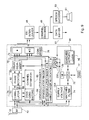
- Figure 3 is presented in another form in Figure 9.
- the demodulator 47 is shown in greater detail as numeral 90.
- Figure 9 has many features in common with Figure 6 and like reference numerals have been applied to like parts for those parts of Figure 6 and Figure 9 which operate in a similar way. Another description of the operation will not be given. However, additional features and their operation will now be described.
- the rake receiver comprises a motion indicator (Ml) 79 connected to the CPU 75.
- the Ml 79 identifies a stationary state of the mobile station.
- This can be in addition to the acceleration transducer 36 or may be present instead of it.
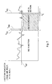
- a motion indicator value M(n,k) is calculated by the Ml 79 to give an indication of motion which has occurred between a current measurement n and a previous measurement indicated by a integer k. There are a number of previous measurements k. The larger the value of k, the earlier the measurement. The difference between the time when measurement k having its maximum value of k limit (k limit is a configurable constant) was measured and when measurement n was measured is shown in Figure 7 by a period D k . Period D k is a measurement margin that is chosen to be suitable to determine whether the mobile station is stationary or in motion depending on MT change with respect to time.
- the motion indicator value is calculated as follows: where
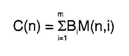
- the combined motion indicator value is: where B i is a configurable constant; and parameter (m) is an upper limit value of the variable (i) in the combined motion indicator formula and is also a configurable constant.
- detecting motion of the mobile station may be determined by a motion sensor unit such as an acceleration transducer 36 having three sensitive axes one for each orthogonal direction in space.
- the combined motion indicator value C(n) is compared by the Ml 79 against a preset motion threshold value C MT . Alternatively, it may be compared by the CPU 75 or the searcher 76. It may be compared by two or more of these blocks acting together.
- C MT is a configurable constant. If the motion indicator value C(n) is below the motion threshold value C MT the activity of the searcher 76 is reduced. For example, more demodulator fingers 71, 72 and 73 may be allocated for a moving mobile station than for a stationary one.
- Figure 7 shows deactivation of a demodulator finger at T TS and reactivation at T RS .
- the rate at which the searcher 76 measures the assigned (dedicated) channel may be reduced to a minimum (such as not measuring so frequently in idle mode frames). This occurs at time T RM , which, at its earliest, may be equal to T TS . This reduced activity lasts, at the latest, until the moment when the demodulator finger is re-activated (that is at time T RS ). Ending of the reduced activity can occur as a result of the measured margin of C(n) delta value (that is the minimum measurement margin between n and n-k limit ) having a bigger value than the motion threshold value C MT .
- the power saving step involves the rake receiver 90 doing certain functional procedures less frequently.
- a further power saving step such as deactivating a modulator finger may not be carried out.
- This may apply in an embodiment in which there is only one demodulator which monitors the assigned and non-assigned channels. It may do this by monitoring the non-assigned channel during the idle mode frames.
- the mobile station While the mobile station is stationary it finds the pilot radio frequency of the important downlink transmission signals of each nearby base station such as active downlink, the candidate downlink used in cell re-selection and handover situations as new downlink resulting to be best available serving cell.
- the new serving cell is selected according to neighbour cell measurement signal procedure described in technical specification TS 25.304.
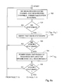
- a rake receiver of a WCDMA mobile station during a stationary period is shown in a series of logical steps in Figure 8.
- the mobile station is measuring a dedicated channel and neighbouring channels. All of the demodulator fingers are allocated.
- step 101 it is determined that the mobile station is stationary at a time of T TS - D k . This is determined by checking if the average or weighted average value of the motion indicator value C(n) is less than or equal to the motion threshold value C MT .
- the mobile station stops measuring neighbouring cells and deactivates the related demodulator finger (step 104). If it is confirmed that the average or weighted average value of the motion indicator value C(n) remains less than or equal to the motion threshold value C MT until a certain time period (T RM ) has elapsed, the mobile station reduces the rate at which the searcher 76 makes assigned channel measurements (step 106).
- the reduced finger allocation of the rake receiver 90 demodulator section and reduced searcher 76 activity is maintained at minimum levels until it is observed that the motion indicator value C(n) is exceeding the motion indicator threshold value C MT . This is recognised to occur when the average or weighted average value of C(n) exceeds the motion threshold value C MT and remains greater until the expiration of a delay time D k (the motion indicator measurement summation margin from n to n-k limit expressed in time).
- the searcher 76 activity is restored to normal activity to process neighbouring cell and assigned channel measurements as frequently as possible as specified in TS 25.304. Then at least one rake receiver finger can be re-allocated to do neighbouring cell measurements in such a way that firstly the circuitry of the demodulator finger section is switched on and secondly the searcher 76 configures its functioning conditions to support neighbouring cell measurement scheme according to 3GPP UMTS specifications.
- the measured channel is the common control physical channel (CCPCH) (step 106).
- CPCH common control physical channel
- CPICH common primary pilot channel
- the reduced measurement frequency of the dedicated channel may start at a time T RM which is prior to the deactivation time (T TS ) of a demodulator finger of the rake receiver 90.
- T RM deactivation time
- the reduction of activity of the searcher 76 may occur first for neighbouring cell measurements making the measurement rate slow down.
- the assigned channel measurement rate may also slow down at the same moment. In relation to Figure 8 this would mean swapping the positions of the steps 104 and 106.
- this step (step 106) may also include reduction in searched activity processed for neighbouring cell measurement.
- the logic applied for motion indicator determination can be written as a computer program as follows:
- the searcher 76 configures the finger allocation by using the matched filter 74 controlling the correlator functionality of each finger of the rake receiver 90.
- the searcher 76 also controls power supplied to the demodulator finger circuitry by operating a switch arrangement k1, k2 or k3 in such a way that individual demodulator fingers can be deactivated by being connected to ground 200 instead of to a supply voltage source 201. In this way supply voltage consumption is reduced. Any suitable means can be adopted so that individual demodulator fingers may be deactivated.
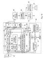
- FIG 10 shows another embodiment of the invention in which Complementary metal oxide semiconductor (CMOS) circuitry is used for rake receiver demodulator fingers.
- CMOS circuitry has very low static power dissipation. This enables devices in an inverter or logic gate always to be off when no voltage state changes occurs. The only residual current drawn is from leakage current, typically ⁇ 1 ⁇ A.
- the rake receiver 90 demodulator finger circuitry is switched off the power consumption reduction in CMOS circuits close to zero is achieved by preventing voltage state change occurrences.
- the searcher 76 makes power switching off from at least one finger of the rake receiver demodulator section the searcher 76 controls the finger circuitry so as to prevent any Rx signal from entering the timing pulse train at the input of the demodulator finger.
- the clock pulse disconnection to the demodulator finger of the rake receiver 90 demodulator is done, for example, by having control switches k10, k11 and k12 to disconnect the clock pulse connection from being passed to the receiver circuitry 90 demodulator fingers and instead to be connected, for example, to ground 200.
- WCDMA is used as an example of a system where a method according to the invention can be implemented.
- the method and apparatus according to the invention are not restricted to those used in third generation cellular receivers. They can be applied also to other types of mobile stations and radio networks.
Landscapes
- Engineering & Computer Science (AREA)
- Computer Networks & Wireless Communication (AREA)
- Signal Processing (AREA)
- Mobile Radio Communication Systems (AREA)
- Telephone Function (AREA)
Abstract
Description

Stationary_time =
Reduce the finger allocation to "minimized";
Claims (18)
- A method of operating a mobile station comprising the steps of:providing the mobile station with a demodulator;putting the mobile station into an idle mode;measuring a currently assigned channel; anddetecting whether the mobile station is stationary; andreducing the activity of the demodulator if the mobile station is stationary.
- A method according to claim 1 in which the mobile station comprises a plurality of demodulator sub-units.
- A method according to claim 2 in which the step of reducing the activity of the demodulator is carried out by deactivating at least one of the plurality of demodulator sub-units.
- A method according to any preceding claim in which the step of reducing the activity of the demodulator is carried out by deactivating the parts of the demodulator which are concerned with measuring a non-assigned channel.
- A method according to any preceding claim in which the mobile station comprises a plurality of demodulator fingers each of which is used to receive time diversified signals.
- A method according to any preceding claim in which the mobile station comprises a rake receiver.
- A method according to any preceding claim comprising the step of measuring at least one non-assigned channel.
- A method according to claim 1 as it depends from claim 2 in which the step of measuring the at least one non-assigned channel is carried out by at least one of the plurality of demodulator sub-units.
- A method according to claim 8 in which the step of measuring the at least one non-assigned channel and the step of measuring the currently assigned channel are carried out by the same demodulator sub-unit.
- A method according to claim 8 or claim 9 in which the step of measuring the at least one non-assigned channel is carried out by at least one of the plurality of demodulator sub-units during its idle mode.
- A method according to any preceding claim in which the assigned channel is the common control physical channel CCPCH.
- A method according to any of claims 1 to 10 in which the assigned channel is the common primary pilot channel CPICH.
- A method according to any preceding claim in which a motion indicator is calculated to determine whether the mobile station is stationary.
- A method according to claim 13 in which the motion indicator is calculated in a motion detector present in the mobile station.
- A method according to claim 13 or claim 14 in which the motion indicator is used to detect changes in power level or in other downlink measurement parameters in a received signal.
- A telecommunications system operating according to the method of any of the preceding claims.
- A mobile station comprising a receiver having a radio frequency block and a demodulator, means for putting the mobile station into an idle mode, means for measuring a currently assigned channel, a motion indicator for detecting if the mobile station is stationary and an activity controller for reducing the activity of the demodulator if the mobile station is stationary.
- A telecommunications system comprising a mobile station according to claim 17.
Applications Claiming Priority (2)
| Application Number | Priority Date | Filing Date | Title |
|---|---|---|---|
| FI20000700 | 2000-03-24 | ||
| FI20000700A FI20000700L (en) | 2000-03-24 | 2000-03-24 | A mobile phone with enhanced power saving feature |
Publications (3)
| Publication Number | Publication Date |
|---|---|
| EP1146653A2 true EP1146653A2 (en) | 2001-10-17 |
| EP1146653A3 EP1146653A3 (en) | 2003-11-19 |
| EP1146653B1 EP1146653B1 (en) | 2007-08-15 |
Family
ID=8558030
Family Applications (1)
| Application Number | Title | Priority Date | Filing Date |
|---|---|---|---|
| EP01101593A Expired - Lifetime EP1146653B1 (en) | 2000-03-24 | 2001-01-25 | Power saving in mobile stations |
Country Status (6)
| Country | Link |
|---|---|
| US (1) | US7035676B2 (en) |
| EP (1) | EP1146653B1 (en) |
| JP (1) | JP2001320321A (en) |
| AT (1) | ATE370552T1 (en) |
| DE (1) | DE60129874T2 (en) |
| FI (1) | FI20000700L (en) |
Cited By (6)
| Publication number | Priority date | Publication date | Assignee | Title |
|---|---|---|---|---|
| EP1869788A4 (en) * | 2005-04-01 | 2009-11-04 | Ixi Mobile R & D Ltd | Efficient server polling system and method |
| WO2010138601A3 (en) * | 2009-05-27 | 2011-04-14 | Qualcomm Incorporated | Movement sensor uses in communication systems |
| EP1580909A3 (en) * | 2004-03-23 | 2013-10-02 | Warren & Lewis Investment Corporation | Mobile terminal, reception decision method in a mobile terminal and program |
| US9253721B2 (en) | 2011-09-28 | 2016-02-02 | Fujitsu Limited | Activation of supplementary transmission unit |
| US9380519B2 (en) | 2013-03-13 | 2016-06-28 | Qualcomm Incorporated | Using motion to improve local wireless network connectivity |
| US9380520B2 (en) | 2013-03-13 | 2016-06-28 | Qualcomm Incorporated | Using motion to improve local wireless network connectivity |
Families Citing this family (51)
| Publication number | Priority date | Publication date | Assignee | Title |
|---|---|---|---|---|
| US7187730B1 (en) | 2001-03-21 | 2007-03-06 | Marvell International Ltd. | Method and apparatus for predicting CCK subsymbols |
| US7145969B1 (en) * | 2001-03-21 | 2006-12-05 | Marvell International Ltd. | Method and apparatus for complementary code keying |
| US7792074B2 (en) * | 2001-03-28 | 2010-09-07 | Qualcomm Incorporated | Method and apparatus for channel management for point-to-multipoint services in a communication system |
| US9100457B2 (en) | 2001-03-28 | 2015-08-04 | Qualcomm Incorporated | Method and apparatus for transmission framing in a wireless communication system |
| JP2002320260A (en) * | 2001-04-19 | 2002-10-31 | Toshiba Corp | Mobile communication terminal |
| US6584331B2 (en) | 2001-10-09 | 2003-06-24 | Nokia Corporation | Use of received signal strength indicator (RSSI) and global positioning system (GPS) to reduce power consumption in mobile station |
| US7352868B2 (en) * | 2001-10-09 | 2008-04-01 | Philip Hawkes | Method and apparatus for security in a data processing system |
| US7649829B2 (en) | 2001-10-12 | 2010-01-19 | Qualcomm Incorporated | Method and system for reduction of decoding complexity in a communication system |
| US7236475B2 (en) * | 2002-02-06 | 2007-06-26 | Ntt Docomo, Inc. | Using subnet relations to conserve power in a wireless communication device |
| US20030224730A1 (en) * | 2002-04-29 | 2003-12-04 | Peter Muszynski | Method and apparatus for selection of downlink carriers in a cellular system using multiple downlink carriers |
| DE10222970A1 (en) * | 2002-05-23 | 2004-02-05 | Philips Intellectual Property & Standards Gmbh | Method for network connection of a UMTS mobile radio device |
| KR100566208B1 (en) * | 2002-06-14 | 2006-03-29 | 삼성전자주식회사 | Method and apparatus for soft combining of mbms service data in a cdma mobile communication system providing mbms service |
| MXPA04011375A (en) * | 2002-06-27 | 2005-02-14 | Interdigital Tech Corp | RADIO NETWORK CONTROLLER FOR EXCHANGE OF EQUIPMENT INFORMATION. |
| US7512423B2 (en) * | 2002-08-12 | 2009-03-31 | Broadcom Corporation | Power management of radio transceiver elements |
| US7599655B2 (en) | 2003-01-02 | 2009-10-06 | Qualcomm Incorporated | Method and apparatus for broadcast services in a communication system |
| US8306562B2 (en) * | 2003-05-29 | 2012-11-06 | Texas Instruments Incorporated | Signal-to-interference ratio target control for multi-data-rate communication systems |
| US8718279B2 (en) | 2003-07-08 | 2014-05-06 | Qualcomm Incorporated | Apparatus and method for a secure broadcast system |
| US8724803B2 (en) | 2003-09-02 | 2014-05-13 | Qualcomm Incorporated | Method and apparatus for providing authenticated challenges for broadcast-multicast communications in a communication system |
| US7546132B2 (en) * | 2004-04-19 | 2009-06-09 | Lg Electronics, Inc. | Communication of point to multipoint service information in wireless communication system |
| EP1754328A4 (en) * | 2004-05-13 | 2008-06-11 | Sandlinks Systems Ltd | Low power fast impulse radio synchronization |
| US7280828B1 (en) * | 2004-05-24 | 2007-10-09 | Cingular Wireless Ii, Llc | Service grant for GSM wireless networks based on signal strength |
| CN102655446B (en) * | 2004-06-30 | 2016-12-14 | 亚马逊科技公司 | Apparatus and method and communication means for control signal transmission |
| JP4448403B2 (en) * | 2004-08-16 | 2010-04-07 | 富士通株式会社 | Power level measuring apparatus and mobile station |
| GB0419947D0 (en) * | 2004-09-08 | 2004-10-13 | British Telecomm | High data rate demodulation system |
| GB0419946D0 (en) * | 2004-09-08 | 2004-10-13 | British Telecomm | High data rate demodulation system |
| US8406251B2 (en) * | 2004-10-06 | 2013-03-26 | Broadcom Corporation | Method and system for processing multipath clusters |
| US8045599B2 (en) * | 2005-02-17 | 2011-10-25 | Sony Corporation | Selection of training sequences for multiple-in multiple-out transmissions |
| KR100713007B1 (en) * | 2005-04-29 | 2007-04-30 | 삼성전자주식회사 | Mobile communication terminal and its cell signal power measurement cycle adjustment method |
| US7440730B2 (en) * | 2005-06-30 | 2008-10-21 | Intel Corporation | Device, system and method of multiple transceivers control |
| JP4762680B2 (en) * | 2005-11-04 | 2011-08-31 | 株式会社エヌ・ティ・ティ・ドコモ | Carrier method notification method, neighboring cell measurement method, base station apparatus and mobile station apparatus |
| ATE534264T1 (en) | 2005-12-14 | 2011-12-15 | Research In Motion Ltd | METHOD AND DEVICE FOR TERMINAL-BASED RADIO CONTROL IN A UMTS NETWORK |
| US7555319B2 (en) * | 2006-03-21 | 2009-06-30 | Telefonaktiebolaget L M Ericsson (Publ) | Adaptive power efficient radio environment measurements |
| ATE484937T1 (en) | 2006-05-17 | 2010-10-15 | Research In Motion Ltd | METHOD AND SYSTEM FOR DISPLAYING A CAUSE FOR A DISCONNECT OF A SIGNALING CONNECTION IN A UMTS NETWORK |
| US7519401B2 (en) * | 2006-06-08 | 2009-04-14 | Telefonaktiebolaget L M Ericsson (Publ) | Efficient radio environment condition recognition |
| US7848388B2 (en) * | 2006-08-08 | 2010-12-07 | Sony Ericsson Mobile Communications Ab | Minimizing estimation time for rake fingers with help of a speed sensor |
| KR100965663B1 (en) * | 2007-01-30 | 2010-06-24 | 삼성전자주식회사 | Method and apparatus for transmitting / receiving downlink synchronization channel for wireless communication system |
| TWI333752B (en) * | 2007-03-27 | 2010-11-21 | Asustek Comp Inc | Mobile communication device and power conservation method thereof |
| US20080259551A1 (en) * | 2007-04-20 | 2008-10-23 | Gotive A.S. | Modular computing device |
| WO2009050538A1 (en) * | 2007-10-18 | 2009-04-23 | Freescale Semiconductor, Inc. | Prolonging internal power supply life in a mobile communication device |
| US8208950B2 (en) | 2007-11-13 | 2012-06-26 | Research In Motion Limited | Method and apparatus for state/mode transitioning |
| DE102007057607A1 (en) * | 2007-11-28 | 2009-06-25 | T-Mobile Internationale Ag | Method for reducing the power consumption in a mobile radio network with at least two supply levels |
| CN101562834B (en) * | 2008-04-16 | 2014-04-09 | 三星电子株式会社 | Method and system supporting macro base station to be switched over to household base station |
| MX2011004888A (en) * | 2008-11-10 | 2011-05-30 | Research In Motion Ltd | METHOD AND APPLIANCE OF TRANSITION TO AN EFFICIENT STATUS OF BATTERY OR CONFIGURATION WHEN INDICATING THE END OF THE TRANSMISSION OF DATA IN LONG-TERM EVOLUTION. |
| FR2943193B1 (en) * | 2009-03-13 | 2011-04-01 | St Ericsson Sa | METHOD FOR ASSIGNING AND RELEASING A CORRELATOR IN A RECEIVER OF RAKE TYPE AND RECEIVER FOR IMPLEMENTING THE METHOD |
| BR112012012356B1 (en) | 2009-11-23 | 2021-05-04 | Blackberry Limited | methods and user equipment for processing indication messages |
| US8811451B2 (en) * | 2011-10-04 | 2014-08-19 | Qualcomm Incorporated | Apparatus and method for selection of a set of cells for interference cancellation in a wireless communication system |
| US8989743B2 (en) | 2012-08-28 | 2015-03-24 | Apple Inc. | Battery conservation in stationary conditions for a wireless device |
| US20150215860A1 (en) * | 2014-01-30 | 2015-07-30 | Qualcomm Incorporated | Subscription acquisition time |
| US10304341B1 (en) * | 2018-02-09 | 2019-05-28 | International Business Machines Corporation | Vehicle and bicycle communication to avoid vehicle door crash accidents |
| WO2021069077A1 (en) * | 2019-10-10 | 2021-04-15 | Telefonaktiebolaget Lm Ericsson (Publ) | Adaptive user equipment operation mode |
| US11468045B2 (en) * | 2020-04-17 | 2022-10-11 | Microsoft Technology Licensing, Llc | Transactional support for non-relational database |
Family Cites Families (19)
| Publication number | Priority date | Publication date | Assignee | Title |
|---|---|---|---|---|
| US5613235A (en) * | 1995-06-29 | 1997-03-18 | Nokia Mobile Phones Limited | Operation of a radiotelephone in a synchronous extended standby mode for conserving battery power |
| JPH0998465A (en) | 1995-09-29 | 1997-04-08 | Nec Corp | Portable radio telephone control method and portable radio telephone set |
| US5930288A (en) * | 1996-05-06 | 1999-07-27 | Motorola, Inc. | Time-shared lock indicator circuit and method for power control and traffic channel decoding in a radio receiver |
| US6067460A (en) * | 1996-05-23 | 2000-05-23 | Nokia Mobile Phones Limited | Mobile station having enhanced standby mode |
| JP3105786B2 (en) * | 1996-06-13 | 2000-11-06 | 松下電器産業株式会社 | Mobile communication receiver |
| US5799256A (en) * | 1996-07-17 | 1998-08-25 | Motorola, Inc. | Battery saving method and communication device using prediction of user location, movement and actions |
| US5918170A (en) * | 1996-08-13 | 1999-06-29 | Nokia Mobile Phones Limited | Synchronizing radio telephone to receive every Nth overhead message train |
| JP3111909B2 (en) * | 1996-09-27 | 2000-11-27 | 松下電器産業株式会社 | Mobile phone |
| JPH1198071A (en) * | 1997-09-20 | 1999-04-09 | Matsushita Electric Ind Co Ltd | CDMA mobile radio terminal |
| US6269075B1 (en) * | 1998-01-26 | 2001-07-31 | Nokia Mobile Phones Limited | Finger assignment in a CDMA rake receiver |
| JPH11261523A (en) * | 1998-03-09 | 1999-09-24 | Oki Electric Ind Co Ltd | Rake reception device |
| JPH11313357A (en) * | 1998-04-28 | 1999-11-09 | Matsushita Electric Ind Co Ltd | Handover method and transmission / reception device |
| US6385460B1 (en) * | 1998-05-26 | 2002-05-07 | Conexant Systems, Inc. | Power management system for a mobile unit by reduced neighbor cell scanning |
| US6370133B1 (en) * | 1998-07-10 | 2002-04-09 | Hyundai Electronics America, Inc. | CDMA receiver and method of operation |
| JP2000083010A (en) * | 1998-09-04 | 2000-03-21 | Toshiba Corp | Rake receiver and speed detection circuit |
| US6532222B1 (en) * | 1998-11-05 | 2003-03-11 | Lucent Technologies Inc. | Apparatus and methods for improving the assignment of parallel demodulators to multipaths of wireless signals |
| US6343094B1 (en) * | 1999-01-22 | 2002-01-29 | Sharp Laboratories Of America, Inc. | Spread spectrum signal receiving method and apparatus for CDMA cellular communication |
| US6289228B1 (en) * | 1999-07-20 | 2001-09-11 | Motorola, Inc. | Method and apparatus for reducing power consumption of a communication device |
| US6539006B1 (en) * | 1999-08-05 | 2003-03-25 | Ericsson Inc. | Mobile station capable of determining base station suitability |
-
2000
- 2000-03-24 FI FI20000700A patent/FI20000700L/en not_active Application Discontinuation
-
2001
- 2001-01-25 DE DE60129874T patent/DE60129874T2/en not_active Expired - Lifetime
- 2001-01-25 AT AT01101593T patent/ATE370552T1/en not_active IP Right Cessation
- 2001-01-25 EP EP01101593A patent/EP1146653B1/en not_active Expired - Lifetime
- 2001-03-22 US US09/814,989 patent/US7035676B2/en not_active Expired - Fee Related
- 2001-03-26 JP JP2001087815A patent/JP2001320321A/en active Pending
Cited By (8)
| Publication number | Priority date | Publication date | Assignee | Title |
|---|---|---|---|---|
| EP1580909A3 (en) * | 2004-03-23 | 2013-10-02 | Warren & Lewis Investment Corporation | Mobile terminal, reception decision method in a mobile terminal and program |
| EP1869788A4 (en) * | 2005-04-01 | 2009-11-04 | Ixi Mobile R & D Ltd | Efficient server polling system and method |
| WO2010138601A3 (en) * | 2009-05-27 | 2011-04-14 | Qualcomm Incorporated | Movement sensor uses in communication systems |
| US8843181B2 (en) | 2009-05-27 | 2014-09-23 | Qualcomm Incorporated | Sensor uses in communication systems |
| EP3518586A1 (en) * | 2009-05-27 | 2019-07-31 | QUALCOMM Incorporated | Sensor uses in communication systems |
| US9253721B2 (en) | 2011-09-28 | 2016-02-02 | Fujitsu Limited | Activation of supplementary transmission unit |
| US9380519B2 (en) | 2013-03-13 | 2016-06-28 | Qualcomm Incorporated | Using motion to improve local wireless network connectivity |
| US9380520B2 (en) | 2013-03-13 | 2016-06-28 | Qualcomm Incorporated | Using motion to improve local wireless network connectivity |
Also Published As
| Publication number | Publication date |
|---|---|
| JP2001320321A (en) | 2001-11-16 |
| EP1146653B1 (en) | 2007-08-15 |
| EP1146653A3 (en) | 2003-11-19 |
| FI20000700A7 (en) | 2001-09-25 |
| DE60129874D1 (en) | 2007-09-27 |
| US20010034254A1 (en) | 2001-10-25 |
| ATE370552T1 (en) | 2007-09-15 |
| DE60129874T2 (en) | 2008-05-15 |
| FI20000700A0 (en) | 2000-03-24 |
| FI20000700L (en) | 2001-09-25 |
| US7035676B2 (en) | 2006-04-25 |
Similar Documents
| Publication | Publication Date | Title |
|---|---|---|
| EP1146653B1 (en) | Power saving in mobile stations | |
| Haardt et al. | The td-cdma based utra tdd mode | |
| JP4318860B2 (en) | Method and system for providing personal base station communication | |
| US6606496B1 (en) | Reverse link other cell interference locator and handoff trigger for wireless network | |
| EP1700395B1 (en) | Method and system for determining uplink/downlink path-loss difference | |
| KR100959709B1 (en) | Method and apparatus for controlling communication of data from multiple base stations to one mobile station in a communication system | |
| US20050025096A1 (en) | Method and apparatus for time-sharing channelization code in a CDMA communication system | |
| RU2417562C2 (en) | Detecting control messages for vs-dpnl in wireless communication system | |
| EP1183806B1 (en) | Apparatus and method for gated transmission in cdma communication system | |
| EP1024606A2 (en) | Open loop power control for wireless mobile stations | |
| US7006468B1 (en) | Page monitoring method and apparatus | |
| EP1097527B1 (en) | Method and apparatus for performing an inter-frequency search | |
| US7228147B2 (en) | Method for controlling transmission power | |
| KR20040037170A (en) | Handoff method and apparatus with dual pilots in a communication system | |
| KR101010132B1 (en) | Mobile Handoff Functionality Using Asynchronous Channels in Communication Systems | |
| US20020137513A1 (en) | Communication terminal apparatus and radio communication method | |
| EP1152624A1 (en) | Communication terminal and wireless communication method | |
| US7623484B2 (en) | Methods of multipath acquisition for dedicated traffic channels | |
| US20060268762A1 (en) | Method of path monitoring in a wireless communication system | |
| JP2001069073A (en) | Transmission power control circuit and control method | |
| Futakata et al. | Experimental performance results of IMT-2000 CDMA TDD system | |
| Wang et al. | A study on adaptive setting of the transmission power in SCH for 3G radio cell system | |
| HK1037447B (en) | Method and system for providing personal base station communications |
Legal Events
| Date | Code | Title | Description |
|---|---|---|---|
| PUAI | Public reference made under article 153(3) epc to a published international application that has entered the european phase |
Free format text: ORIGINAL CODE: 0009012 |
|
| AK | Designated contracting states |
Kind code of ref document: A2 Designated state(s): AT BE CH CY DE DK ES FI FR GB GR IE IT LI LU MC NL PT SE TR |
|
| AX | Request for extension of the european patent |
Free format text: AL;LT;LV;MK;RO;SI |
|
| RAP1 | Party data changed (applicant data changed or rights of an application transferred) |
Owner name: NOKIA CORPORATION |
|
| PUAL | Search report despatched |
Free format text: ORIGINAL CODE: 0009013 |
|
| AK | Designated contracting states |
Kind code of ref document: A3 Designated state(s): AT BE CH CY DE DK ES FI FR GB GR IE IT LI LU MC NL PT SE TR |
|
| AX | Request for extension of the european patent |
Extension state: AL LT LV MK RO SI |
|
| 17P | Request for examination filed |
Effective date: 20040519 |
|
| AKX | Designation fees paid |
Designated state(s): AT BE CH CY DE DK ES FI FR GB GR IE IT LI LU MC NL PT SE TR |
|
| GRAP | Despatch of communication of intention to grant a patent |
Free format text: ORIGINAL CODE: EPIDOSNIGR1 |
|
| GRAS | Grant fee paid |
Free format text: ORIGINAL CODE: EPIDOSNIGR3 |
|
| GRAA | (expected) grant |
Free format text: ORIGINAL CODE: 0009210 |
|
| AK | Designated contracting states |
Kind code of ref document: B1 Designated state(s): AT BE CH CY DE DK ES FI FR GB GR IE IT LI LU MC NL PT SE TR |
|
| REG | Reference to a national code |
Ref country code: GB Ref legal event code: FG4D |
|
| REG | Reference to a national code |
Ref country code: CH Ref legal event code: EP |
|
| REG | Reference to a national code |
Ref country code: IE Ref legal event code: FG4D |
|
| REF | Corresponds to: |
Ref document number: 60129874 Country of ref document: DE Date of ref document: 20070927 Kind code of ref document: P |
|
| ET | Fr: translation filed | ||
| PG25 | Lapsed in a contracting state [announced via postgrant information from national office to epo] |
Ref country code: FI Free format text: LAPSE BECAUSE OF FAILURE TO SUBMIT A TRANSLATION OF THE DESCRIPTION OR TO PAY THE FEE WITHIN THE PRESCRIBED TIME-LIMIT Effective date: 20070815 Ref country code: ES Free format text: LAPSE BECAUSE OF FAILURE TO SUBMIT A TRANSLATION OF THE DESCRIPTION OR TO PAY THE FEE WITHIN THE PRESCRIBED TIME-LIMIT Effective date: 20071126 Ref country code: NL Free format text: LAPSE BECAUSE OF FAILURE TO SUBMIT A TRANSLATION OF THE DESCRIPTION OR TO PAY THE FEE WITHIN THE PRESCRIBED TIME-LIMIT Effective date: 20070815 |
|
| NLV1 | Nl: lapsed or annulled due to failure to fulfill the requirements of art. 29p and 29m of the patents act | ||
| PG25 | Lapsed in a contracting state [announced via postgrant information from national office to epo] |
Ref country code: LI Free format text: LAPSE BECAUSE OF FAILURE TO SUBMIT A TRANSLATION OF THE DESCRIPTION OR TO PAY THE FEE WITHIN THE PRESCRIBED TIME-LIMIT Effective date: 20070815 Ref country code: AT Free format text: LAPSE BECAUSE OF FAILURE TO SUBMIT A TRANSLATION OF THE DESCRIPTION OR TO PAY THE FEE WITHIN THE PRESCRIBED TIME-LIMIT Effective date: 20070815 Ref country code: CH Free format text: LAPSE BECAUSE OF FAILURE TO SUBMIT A TRANSLATION OF THE DESCRIPTION OR TO PAY THE FEE WITHIN THE PRESCRIBED TIME-LIMIT Effective date: 20070815 |
|
| REG | Reference to a national code |
Ref country code: CH Ref legal event code: PL |
|
| PG25 | Lapsed in a contracting state [announced via postgrant information from national office to epo] |
Ref country code: BE Free format text: LAPSE BECAUSE OF FAILURE TO SUBMIT A TRANSLATION OF THE DESCRIPTION OR TO PAY THE FEE WITHIN THE PRESCRIBED TIME-LIMIT Effective date: 20070815 |
|
| PG25 | Lapsed in a contracting state [announced via postgrant information from national office to epo] |
Ref country code: GR Free format text: LAPSE BECAUSE OF FAILURE TO SUBMIT A TRANSLATION OF THE DESCRIPTION OR TO PAY THE FEE WITHIN THE PRESCRIBED TIME-LIMIT Effective date: 20071116 Ref country code: DK Free format text: LAPSE BECAUSE OF FAILURE TO SUBMIT A TRANSLATION OF THE DESCRIPTION OR TO PAY THE FEE WITHIN THE PRESCRIBED TIME-LIMIT Effective date: 20070815 |
|
| PLBE | No opposition filed within time limit |
Free format text: ORIGINAL CODE: 0009261 |
|
| STAA | Information on the status of an ep patent application or granted ep patent |
Free format text: STATUS: NO OPPOSITION FILED WITHIN TIME LIMIT |
|
| PG25 | Lapsed in a contracting state [announced via postgrant information from national office to epo] |
Ref country code: SE Free format text: LAPSE BECAUSE OF FAILURE TO SUBMIT A TRANSLATION OF THE DESCRIPTION OR TO PAY THE FEE WITHIN THE PRESCRIBED TIME-LIMIT Effective date: 20071115 |
|
| 26N | No opposition filed |
Effective date: 20080516 |
|
| PG25 | Lapsed in a contracting state [announced via postgrant information from national office to epo] |
Ref country code: MC Free format text: LAPSE BECAUSE OF NON-PAYMENT OF DUE FEES Effective date: 20080131 |
|
| PG25 | Lapsed in a contracting state [announced via postgrant information from national office to epo] |
Ref country code: IE Free format text: LAPSE BECAUSE OF NON-PAYMENT OF DUE FEES Effective date: 20080125 |
|
| PG25 | Lapsed in a contracting state [announced via postgrant information from national office to epo] |
Ref country code: CY Free format text: LAPSE BECAUSE OF FAILURE TO SUBMIT A TRANSLATION OF THE DESCRIPTION OR TO PAY THE FEE WITHIN THE PRESCRIBED TIME-LIMIT Effective date: 20070815 |
|
| PGFP | Annual fee paid to national office [announced via postgrant information from national office to epo] |
Ref country code: FR Payment date: 20100208 Year of fee payment: 10 |
|
| PGFP | Annual fee paid to national office [announced via postgrant information from national office to epo] |
Ref country code: GB Payment date: 20100120 Year of fee payment: 10 Ref country code: DE Payment date: 20100121 Year of fee payment: 10 |
|
| PG25 | Lapsed in a contracting state [announced via postgrant information from national office to epo] |
Ref country code: LU Free format text: LAPSE BECAUSE OF NON-PAYMENT OF DUE FEES Effective date: 20080125 |
|
| PG25 | Lapsed in a contracting state [announced via postgrant information from national office to epo] |
Ref country code: TR Free format text: LAPSE BECAUSE OF FAILURE TO SUBMIT A TRANSLATION OF THE DESCRIPTION OR TO PAY THE FEE WITHIN THE PRESCRIBED TIME-LIMIT Effective date: 20070815 |
|
| PG25 | Lapsed in a contracting state [announced via postgrant information from national office to epo] |
Ref country code: IT Free format text: LAPSE BECAUSE OF NON-PAYMENT OF DUE FEES Effective date: 20080131 |
|
| GBPC | Gb: european patent ceased through non-payment of renewal fee |
Effective date: 20110125 |
|
| REG | Reference to a national code |
Ref country code: FR Ref legal event code: ST Effective date: 20110930 |
|
| PG25 | Lapsed in a contracting state [announced via postgrant information from national office to epo] |
Ref country code: FR Free format text: LAPSE BECAUSE OF NON-PAYMENT OF DUE FEES Effective date: 20110131 Ref country code: PT Free format text: LAPSE BECAUSE OF FAILURE TO SUBMIT A TRANSLATION OF THE DESCRIPTION OR TO PAY THE FEE WITHIN THE PRESCRIBED TIME-LIMIT Effective date: 20070815 |
|
| PG25 | Lapsed in a contracting state [announced via postgrant information from national office to epo] |
Ref country code: GB Free format text: LAPSE BECAUSE OF NON-PAYMENT OF DUE FEES Effective date: 20110125 |
|
| REG | Reference to a national code |
Ref country code: DE Ref legal event code: R119 Ref document number: 60129874 Country of ref document: DE Effective date: 20110802 |
|
| PG25 | Lapsed in a contracting state [announced via postgrant information from national office to epo] |
Ref country code: DE Free format text: LAPSE BECAUSE OF NON-PAYMENT OF DUE FEES Effective date: 20110802 |