The present invention relates to an upconversion laser
that, with an infrared semiconductor laser of high output or
an external resonance laser as a pump light source, by making
use of upconversion phenomena of a rare earth doped optical
fiber, outputs visible light for display use.
First, an explanation of conventional upconversion due
to a rare earth doped optical fiber will be given in the
following.
As to upconversion to blue light, there is a report in
which infrared light excites tri-valent thulium ions (Tm3+)
to let oscillate with a wavelength of around 480 nm.
According to Japanese Patent Laid-open Publication (KOKAI) No.
HEI 8-307000 titled "Rare earth ion doped short wavelength
laser apparatus, rare earth ion doped short wavelength light
amplifier and rare earth ion doped wavelength converter", an
upconversion is proposed in which wavelengths of
approximately 1200 nm and approximately 650 nm are up-converted
to an wavelength of approximately 480 nm. Though
it says that efficient upconversion can be realized due to
excitation with two wavelengths, a blue wavelength of 480 nm
is a little longer for as the blue light for display use,
being inappropriate for display use.
Similarly, Japanese Patent Laid-open Publication
(KOKAI) No. HEI 7-142806 titled "Rare earth ion doped short
wavelength laser light source" and Japanese Patent Laid-open
Publication No. (KOKAI) HEI 9-107143 titled "Blue up-conversion
laser" disclose the following invention. That is,
by means of an infrared laser of one wavelength (800 to 980
nm, for instance 850 nm), an optical fiber doped by trivalent
praseodymium ion (Pr3+) and trivalent ytterbium ion (Yb3+) can
be excited. By use of laser oscillation of Yb3+ ion of
approximately 1020 nm followed the above excitation, Pr3+ ion
is excited to obtain blue emission of 490 nm.
Thus, it has been proposed to upconvert infrared light
to blue light, however, there has not yet been disclosed to
upconvert to the blue of a wavelength of approximately 470 nm
appropriate for display.
In Japanese Patent Application No. HEI 11-149751 titled
"Up-conversion Fiber Laser", which the present inventors have
proposed, an up-conversion fiber laser is disclosed to obtain
blue light appropriate for display. This application, with a
red emitting superluminescent diode (SLD) as a pump light
source, up-converts to two wavelengths of 450 nm and 480 nm,
followed by mixing thereof to obtain blue color for display.
Though it might be improved in the future, there is a
disadvantage that, at the present time, despite SLD's for
infrared wavelength having been already mass-produced to be
relatively inexpensive, SLD's for red wavelength are rather
expensive from the viewpoint of cost. In addition to this,
there is also another demerit that products of high output
power are difficult to procure.
As a method that outputs red laser light, there is one
that up-convert from infrared wavelength. A Pr3+ ion doped
fiber is practically used in a Pr3+ ion doped optical fiber
amplifier (PDFA) in which with infrared wavelength as a pump
light source, signal of a band of 1.3 µm is amplified.
Other than this, it is known that due to the upconversion,
blue, green and red emissions can be generated.
In "High-power continuous-wave upconversion fiber laser
at room temperature", Optics letter/vol.22, No.11/June 1,
1997, by T. Sandrock et al, they say that from a Pr3+ and Yb3+
ion doped fiber, with exciting light of approximately 850 nm,
635 nm laser light of high output power can be obtained.
Further, similarly, also USP 5,805,631 "Blue, Green,
Orange, and Red Upconversion Laser " proposes to obtain blue,
green, orange and red colors from a Pr3+ and Yb3+ ion doped
fiber.
In employing the Pr3+ and Yb3+ ion doped fiber, pump
light of one wavelength is said to be capable of exciting.
However, from the viewpoint of efficiency, a wavelength
appropriate for ground state absorption (GSA) of Yb3+ and a
wavelength appropriate for excited state absorption (ESA) are
not the same. Accordingly, excitation with one wavelength
constitutes a state of poor efficiency. When assumed
realization of high power laser, this point causes problems.
Now, there are two bands of 630 nm and 680 nm in a red
emission line spectrum of Pr3+ ion. According to "Direct
observation of time-resolved excited state absorption on Tm3+
-doped various glasses using a laser-flash pump-probe
spectroscopy", J. Non-Cryst. Solids, 1997 by S. Kishimoto et
al, these wavelengths are known to be ones appropriate for
ground state absorption (GSA) and excited state absorption
(ESA) of Tm3+ ion.
However, so far, in the case of employing Pr3+ ion, the
up-converted laser light is the final output and is not
employed again as exciting light. Accordingly, precious
properties of Pr3+ ion of having wavelengths appropriate for
excitation of Tm3+ ion is not made the best use of.
An object of the present invention is to provide an
upconversion laser in which a semiconductor laser of high
output power can be used as a pump light source and
wavelengths of the up-converted laser light are ones
appropriate for display.
Another object of the present invention is to provide
an upconversion laser capable of being excited with more
efficient wavelengths.
To achieve the above ends, the present invention
comprises a first upconversion laser performing upconversion
excitation of praseodymium ion (Pr3+), and a second
upconversion laser exciting thulium ion (Tm3+) by laser light
of wavelengths of approximately 635 nm and approximately 685
nm that are obtained from the first upconversion laser. Here,
the output laser light of the second upconversion laser has
wavelengths of approximately 450 nm and/or approximately 480
nm.
Thereby, the wavelengths emitted from Pr3+ ion being
ones just appropriate for excitation of Tm3+ ion, conversion
from red laser light to blue laser light can be performed
with high efficiency. Thereby, as the pump light source,
external resonance type LD, SLD and LD that have high output
power in infrared wavelengths can be used, resulting in blue
laser light optimum for display.
The present invention comprises a first cavity and a
second cavity. The first cavity comprises an external
resonance type laser and a praseodymium ion (Pr3+) doped
fiber, wherein with laser light emitted from the external
resonance type laser as exciting light, the praseodymium ion
is excited by upconversion to emit red light, the red light
being resonated to oscillate laser. The second cavity
comprises a thulium ion (Tm3+) doped optical fiber, wherein
with the red light as exciting light, the thulium ion is
excited by upconversion to generate blue light, the blue
light being resonated to oscillate laser.
Thereby, as the pump light source, external resonance
infrared LD of high output power can be selected, resulting
in use of the selected device of high output power. Even if
high output power is required in displaying a large image
screen, blue laser light most appropriate for display can be
obtained.
Furthermore, the present invention comprises a cavity,
a Pr3+ and Yb3+ ion doped optical fiber, and a resonator
structure. The cavity includes an external resonance laser
that emits two kinds of laser lights of wavelengths of 780 nm
to 900 nm and 950 nm to 1050 nm. The Pr3+ and Yb3+ ion doped
optical fiber is disposed in the cavity and the laser light
is inputted thereon. The resonant structure is disposed in
the cavity, and causes the red light emitted through
upconversion by the optical fiber to resonate.
Thereby, the up-converted red laser light can be
obtained with a high efficiency.
Still further, the present invention comprises a cavity,
a Pr3+ and Yb3+ ion doped optical fiber, and a resonant
structure. The cavity includes an external resonance laser
that emits two kinds of laser lights of wavelengths at 780 nm
to 900 nm and 950 nm to 1050 nm. The Pr3+ and Yb3+ ions doped
optical fiber is disposed in the cavity and the laser light
is inputted thereon. The resonant structure is disposed in
the cavity, and causes the green light generated through
upconversion by the optical fiber to resonate.
Thereby, the up-converted green laser light of high
efficiency can be obtained.
Fig. 1 is a constitutional diagram for explaining a
first embodiment of the present invention.
Fig. 2 is a diagram for explaining energy levels of
Pr3+ ion.
Fig. 3 is a diagram for explaining energy levels of
Tm3+ ion.
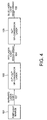
Fig. 4 is a constitutional diagram for explaining a
second embodiment of the present invention.
Fig. 5 is a constitutional diagram for explaining a
third embodiment of the present invention.
Fig. 6 is a constitutional diagram for explaining a
fourth embodiment of the present invention.
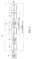
Fig. 7 is a constitutional diagram for explaining a
fifth embodiment of the present invention.
Fig. 8 is a constitutional diagram for explaining a
sixth embodiment of the present invention.
Fig. 9 is a constitutional diagram for explaining a
seventh embodiment of the present invention.
Fig. 10 is a constitutional diagram for explaining an
eighth embodiment of the present invention.
In the present invention, as a preferable example,
upconversion excitation of Pr3+ ion is performed by means of
two kinds of laser lights of wavelengths of approximately 780
to 900 nm and approximately 1010 nm.
As a preferable example, a first upconversion laser
performs upconversion excitation of Pr3+ and ytterbium ion
(Yb3+) doped one.
As a preferable example, a praseodymium ion (Pr3+)
doped optical fiber is doped, in addition to praseodymium ion,
by ytterbium ion (Yb3+).
As a preferable example, host glass of the praseodymium
ion doped optical fiber is any one of indium based fluoride
glass, aluminum based fluoride glass and zirconium based
fluoride glass.
As a preferable example, an external resonant laser
emits laser light of a wavelength of approximately 850 nm to
excite Pr3+ and Yb3+ ions.
As a preferable example, two kinds of laser lights of
wavelengths of from 780 to 900 nm and from 950 to 1050 nm are
used to excite Pr3+ ion.
As a preferable example, as a structure for resonating
of red light or blue light, a fiber grating or a dielectric
mirror is used.
In the following, present embodiments will be explained
in detail with reference to drawings.
Fig. 1 is a constitutional diagram for explaining a
first embodiment of the present invention. In Fig. 1, a pump
light source 101 is one that emits infrared wavelengths, the
wavelengths thereof being two kinds in a range of from 780 to
900 nm and approximately 1010 nm. Laser light 102 emitted
from the pump light source 101 is incident on a Pr3+
upconversion laser 103. The Pr3+ upconversion laser 103
receives the laser light 102 from the pump light source 101
to upconvert the infrared wavelength light into red light of
approximately 635 nm and approximately 685 nm, outputting
laser light.
Red laser light 104 from the Pr3+ upconversion laser
103 is incident on a Tm3+ upconversion laser 105. The Tm3+
upconversion laser 105 receives the red laser light 104 to
upconvert the red wavelength light into blue light of
approximately 450 nm and approximately 480 nm, outputting
blue laser light 106.
Fig. 2 is diagram for explaining energy levels of a
Pr3+ ion. In order to excite from a ground level of the Pr3+
ion, 3H4, to an excited level thereof, 1G4 the Pr3+ ion absorbs
infrared light of a wavelength of approximately 1010 nm.
Further upon absorbing infrared light of a wavelength of from
790 nm to 1010 nm, the Pr3+ ion is excited from the 1G4 level
to further excited levels of 3P0 and 3P1. During transitions
of 3P0 → 3F2 and 3P1 → 3F3, lights of wavelengths of
approximately 635 nm and approximately 685 nm are emitted,
respectively. For the two wavelengths, resonators are formed
to cause stimulated emission of radiation to emit the laser
lights of wavelengths of approximately 635 nm and
approximately 685 nm.
Similarly, with reference to Fig. 3, energy levels of
Tm3+ ion will be explained. Upon absorbing red light of a
wavelength of approximately 685 nm, the Tm3+ ion is excited
from a ground level thereof, 3H6, to an excited level thereof,
3F2. The 3F2 level, though instantaneously dropping to 3H4
level, from the 3H4, upon further absorbing red light of a
wavelength of 635 nm, is further excited to an excited level,
1D2. Upon transition of 1D2 → 3F4, light of a wavelength of
approximately 450 nm is emitted. The 3F4 level further
absorbs red light of a wavelength of 635 nm to be excited to
1G4 level. Upon transition of 1G4 → 3H6, light of a wavelength
of approximately 480 nm is emitted. Of the two wavelengths,
resonators are formed to cause stimulated emission of laser
light of wavelengths of approximately 450 nm and
approximately 480 nm.
As explained above, the wavelengths of light emitted
from Pr3+ ion is ones just appropriate for excitation of Tm3+
ion. That is, for Tm3+ ion, there are wavelengths appropriate
for GSA and ESA in the excitation process leading to an
emission of 450 nm and 480 nm in the vicinities of 685 nm and
635 nm, respectively. Accordingly, conversion from red laser
light to blue laser light can be performed with high
efficiency. Thereby, external resonance type LD, SLD and LD
of high output power in infrared wavelength can be used as an
pump light source, blue laser light most appropriate for
display being obtained.
Next, the present second embodiment will be explained
with reference to Fig. 4. In the present embodiment, instead
of the Pr3+ upconversion laser 103 in Fig. 1, a Pr3+ + Yb3+
upconversion laser 108 is used. Constituent elements the
same with Fig. 1 are given the same reference numerals to
explain.
An Yb3+ ion is characteristic in absorbing a broad
wavelength band centering at 980 nm to be excited to an
energy level in the neighborhood of an excited level of a
Pr3+ ion due to light of 1010 nm. Thereby, the energy thereof
can be given to other ion of close energy level thereto by
the process of energy transfer.
As shown in Fig. 2, a Yb3+ ion absorbs the light
centering 980 nm to cause 2F7/2 → 2F5/2 transition followed by
energy transfer from 2F5/2 level to 1G4 level of Pr3+. Thereby,
the exciting wavelength of a Pr3+ + Yb3+ upconversion laser
can be in the ranges of wavelengths of from 780 nm to 900 nm
and from 950 nm to 1050 nm as the laser light 107 from the
pump light source 101. Thus, the range can be broadened than
for the case of Pr3+ alone.
In addition, since the Yb3+ ion can be excited, though
not so efficient, by the light of approximately 850 nm, the
wavelength of the laser light 107 from the pump light source
101 can be one wavelength of approximately 850 nm. As for
the exciting process and laser light generation action of
Pr3+ and Tm3+ ions after excitation thereof, the explanation
is identical with that of embodiment 1.
Thus, by employing an up-conversion laser in which Yb3+
ion is doped together with Tm3+ ion, as the pump light source,
external resonant type LD, SLD and LD that emit in a broader
wavelength region of infrared can be selected, resulting in
use of a selected device of high output power. Thereby, even
when higher output power is demanded for displaying a larger
size screen, a blue laser light optimum for display can be
obtained.
Furthermore, excitation with one wavelength of
approximately 850 nm being possible, though less efficient,
the configuration can be simplified. In this case, the
present laser can be used as a small and simple light source
for display.
In the above explanation, the pump light source and the
up-conversion laser are separately handled as independent
ones, parts of the cavities of separate resonators can be
constituted to overlap with one another.
Fig. 5 is a diagram for explaining a third embodiment
of the present invention. Specific examples of the Pr3+ up-conversion
laser 103 and the Tm3+ up-conversion laser 105 of
Fig. 1 will be explained.
The laser light 102 emitted from the pump light source
101 is inputted into the Pr3+ up-conversion laser 103. The
Pr3+ up-conversion laser 103 comprises a first reflector 109,
a Pr3+ doped optical fiber 110 and a second reflector 111,
the incident laser light 102 passing through the first
reflector 109 to be incident on the Pr3+ doped optical fiber
110. In the Pr3+ doped optical fiber 110, the laser light 102
from the pump light source 101 is up-converted to emit light
of 635 nm and 685 nm. The first reflector 109 allows for the
laser light 102 from the pump light source 101 to go through
but reflects approximately 100 percent of the light in the
neighborhood of 635 nm and 685 nm.
The second reflector 111 reflects the light of infrared
wavelength and in the neighborhood of 635 nm and 685 nm to
enable to constitute a resonator together with the reflector
109. Thereby, the light in the neighborhood of 635 nm and
685 nm can be amplified due to stimulated emission of
radiation to result in laser oscillation. Reflectivity of
the second reflector 111 in the neighborhood of 635 nm and
685 nm is made lower than that of the first reflector 109,
resulting in emission of laser light 104. The laser light
104 passed through the second reflector 111 is incident on
the Tm3+ up-conversion laser 105.
The Tm3+ up-conversion laser 105 comprises a third
reflector 112, a Tm3+ doped optical fiber 113 and a fourth
reflector 114, the incident laser light 104 going through the
third reflector 112 to enter into the Tm3+ doped optical
fiber 113. At the Tm3+ doped optical fiber 113, the laser
light 104 that is red light is up-converted to emit light of
wavelengths of 450 nm and 480 nm. The third reflector 112,
though permitting the red laser light 104 to pass through,
reflects approximately 100 percent of the light in the
neighborhood of 450 nm and 480 nm.
The fourth reflector 114 reflects the laser light 104
and light of wavelengths of 450 nm and 480 nm. Accordingly,
a resonator can be constituted of the two reflectors 112 and
114, thereby light of 450 nm and 480 nm being amplified due
to stimulated emission of radiation to result in laser
oscillation. Reflectivity of the fourth reflector 114 in the
neighborhood of 450 nm and 480 nm is made lower than that of
the third reflector 112 to permit emitting blue laser light
106 alone.
The respective constituent reflectors of the resonator
is necessary to be constituted for the wavelength being
oscillated to be reflected sufficiently and for the
wavelength that is desired not to oscillate to be reflected
less not to constitute a resonator.
When in the place of the Pr3+ doped optical fiber 110 a
Pr3+ + Yb3+ doped optical fiber is employed, a specific
configuration of an embodiment of Fig. 4 can be obtained. In
this case, because of change of the wavelength of the laser
light 102 from the pump light source 101, characteristics of
the first and second reflectors 109 and 111 must be changed
to the wavelength matching the laser lights to cope with.
Here, as glass base materials for a Pr3+, Tm3+ and Yb3+
doped optical fiber, so that the transition from the excited
upper energy levels to lower energy levels do not result in
meaningless transitions, glasses of which phonon energy is
small are adequate. That is, fluoride based glasses such as
indium based fluoride glass, aluminum based fluoride glass
and zirconium based fluoride glass, of which phonon energy is
said to be small, can be used as base materials for the doped
optical fibers to realize a fiber laser of high emission
efficiency.
Next, with reference to Fig. 6, a fourth embodiment of
the present invention will be explained. Constituent
elements that are the same with Fig. 5 are given the same
reference numerals to explain.
That is, a pump light source 101 comprises an external
resonance LD 115 and a second reflector 111. An end-surface
116 of the external resonance LD 115 and the second reflector
111 constitute a resonator to let emit the light of a
wavelength of laser light 102 due to stimulated emission of
radiation. Inside of a cavity of the resonator, a Pr3+ up-conversion
laser 103 is disposed.
The Pr3+ up-conversion laser 103 comprises a first
reflector 109, a Pr3+ doped optical fiber 110 and a second
reflector 111. The incident laser light 102 goes through the
first reflector 109 and is incident on the Pr3+ doped optical
fiber 110. The Pr3+ doped optical fiber 110 up-converts the
laser light 102 from the pump light source 101 to emit the
light in the neighborhood of 635 nm and 685 nm. The first
reflector 109 allows the laser light 102 to go through but
reflects approximately 100 percent of the light in the
neighborhood of 635 nm and 685 nm.
The second reflector 111 reflects the light of the
wavelength of the laser light 102 and the light in the
neighborhood of 635 nm and 685 nm. Thus, two reflectors 109
and 111 constitute a resonator, thereby the light in the
neighborhood of 635 nm and 685 nm being amplified due to the
stimulated emission of radiation to result in laser
oscillation. Here, reflectivity of the second reflector 111
in the neighborhood of 635 nm and 685 nm is made less than
that of the first reflector 109 to let emit the laser light
104. The laser light 104 gone through the second reflector
111 is incident on a Tm3+ up-conversion laser 105.
For the external resonance LD 115, the Pr3+ up-conversion
laser 103 in the cavity being regarded as a loss,
to make up for the loss to enable amplifying, a plurality of
the external resonance LDs 115 can be arranged to constitute.
Further, a Tm3+ up-conversion laser 105, upon incidence
of the laser light 104, outputs the laser light 106 of the
wavelengths of 450 nm and 480 nm.
Instead of the Pr3+ doped optical fiber 110, a Pr3+ +
Yb3+ doped optical fiber can be disposed. In this case, the
wavelength of the laser light 102 being different,
characteristics of the first and second reflectors 109 and
111 must be changed to wavelength matching the laser light
102 to cope with.
Thus, disposition of the Pr3+ up-conversion laser in
the cavity of the pump light source can give the identical
effect to result in blue laser light optimum for display.
Similarly, the Tm3+ up-conversion laser can be disposed
inside of the cavity of the Pr3+ up-conversion laser.
Next, with reference to a configuration diagram of Fig.
7, a fifth embodiment of the present invention will be
explained. That is, the laser light 102 emitted from the
pump light source 101 is incident on a Pr3+ up-conversion
laser 103. The Pr3+ up-conversion laser 103 comprises a first
reflector 109, a Pr3+ doped optical fiber 110, a Tm3+ doped
up-conversion laser 105 and a second reflector 111, the
incident laser light 102 passing through the first reflector
109 and entering in the Pr3+ doped optical fiber 110. The Pr3+
doped optical fiber 110 up-converts the laser light 102 from
the pump light source 101 to emit the light of 635 nm and 685
nm. The first reflector 109 permits the laser light 102 from
the pump light source 101 to go through but reflects
approximately 100 percent of the light in the neighborhood of
635 nm and 685 nm.
The second reflector 111 reflects approximately 100
percent of the light in the neighborhood of 635 nm and 685 nm.
Thus, two reflectors 109 and 111 constitute a resonator,
thereby the light in the neighborhood of 635 nm and 685 nm
being amplified due to the stimulated emission of radiation
to result in laser oscillation. Here, the second reflector
111 let the laser light 106 generated at the Tm3+ doped up-conversion
laser 105 go through.
The laser light 104 enters into the Tm3+ up-conversion
laser 105. The Tm3+ doped up-conversion laser 105 comprises a
third reflector 112, a Tm3+ doped optical fiber 113 and a
fourth reflector 114, the incident laser light 104 passing
through the third reflector 112, entering into the Tm3+ doped
optical fiber 113. The Tm3+ doped optical fiber 113 up-converts
the laser light 104 that is red to emit the light of
wavelengths of 450 nm and 480 nm.
The third reflector 112 permits the red laser light 104
to go through but reflects approximately 100 percent of the
light in the neighborhood of 450 nm and 480 nm and the light
of the laser light from the pump light source 102.
The fourth reflector 114 reflects the light in the
neighborhood of 450 nm and 480 nm. Thus, two reflectors 112
and 114 constitute a resonator, thereby the light in the
neighborhood of 450 nm and 480 nm being amplified due to the
stimulated emission of radiation to result in laser
oscillation. Here, the reflectivity of the fourth reflector
114 in the neighborhood of 450 nm and 480 nm is made smaller
than that of the third reflector 112 to let emit the blue
laser light 106 alone.
In the above, the second and fourth reflectors 111 and
114 are separately explained. However, these can be combined
into one body, reflectivity of which in the neighborhood of
450 nm and 480 nm is made smaller than that of the third
reflector 112, and reflectivity of the red laser light 104 of
which is approximately 100 percent.
Fig. 8 is a constitution diagram for explaining a sixth
embodiment of the present invention. In the present
embodiment, in a cavity of the pump light source 101 a Pr3+
doped optical fiber 110 of a Pr3+ up-conversion laser 103 is
placed, further in a cavity of the Pr3+ up-conversion laser
103 a Tm3+ up-conversion laser 105 is placed.
In this case, a third reflector 112 lets the laser
light 104 go through and reflect approximately 100 percent of
the light in the neighborhood of 450 nm and 480 nm. A fourth
reflector 114 reflects approximately 100 percent of the laser
light 104 and lets part of the light in the neighborhood of
450 nm and 480 nm go through to output the laser light 106.
Thereby, a resonator of the pump light source 101 is
constituted of an end-surface 116 and the third reflector 112,
and a resonator of the Pr3+ up-conversion laser 103 is
constituted of the first reflector 109 and the fourth
reflector 114.
Fluoride based glasses such as indium based fluoride
glass, aluminum based fluoride glass and zirconium based
fluoride glass, which are said to have small phonon energy
thereof, are naturally adequate for the base materials for
the doped optical fibers 110 and 113.
The reflectors can be realized by means of a dielectric
mirror in which the reflectivity thereof is tailored to the
respective wavelengths or by means of fiber grating. In the
case of the fiber grating being used, simultaneous tailoring
of the reflectivity to a plurality of wavelengths being
difficult, a plurality of fiber gratings for each wavelengths
are arranged. That is, the respective reflectivity of each
wavelength that is designated to each reflector in the above
explanation is realized in one body of a plurality of fiber
gratings, the fiber gratings being only arranged to cope with.
Even in the configurations explained in the above, as
the pump light sources of infrared wavelength such as the
external resonance LD, SLD and LD of high output power can be
used, resulting in blue laser light optimum for display.
In each embodiments of Figs.6 to 8, in the place of the
respective Pr3+ doped optical fibers 110 a Pr3+ + Yb3+ doped
optical fiber that is explained in embodiment of Fig. 4 can
be used. In this case, the wavelength of the laser light 102
from the pump light source 101 being different,
characteristics of each reflectors are tailored to the
wavelength matching the laser light 102 to cope with.
Fig. 9 is a configuration diagram for explaining a
seventh embodiment of the present invention. The pump light
source 101 comprises an external resonance LD 115 and a
second reflector 111. An end-surface 116 of the external
resonance LD 115 and the second reflector 111 constitute a
resonator to let emit the light of wavelength of the laser
light 102 due to the stimulated emission of radiation. In
the cavity of the resonator, a Pr3+ + Yb3+ up-conversion laser
103 is disposed. The Pr3+ + Yb3+ up-conversion laser 103
comprises a first reflector 109, a Pr3+ + Yb3+ doped optical
fiber 118 and a second reflector 111, the incident laser
light 102 passing through the first reflector 109 to enter
into the Pr3+ + Yb3+ doped optical fiber 118. The Pr3+ + Yb3+
doped optical fiber 118 up-converts the laser light 102 from
the pump light source 101 to let emit the light in the
neighborhood of 635 nm and 685 nm. The first reflector 109
allows the laser light 102 to pass through but reflects
approximately 100 percent of the light in the neighborhood of
635 nm.
The second reflector 111 reflects the light of the
wavelength of the laser light 102 and the light in the
neighborhood of 635 nm. Thus, two reflectors 109 and 111
constitute a resonator, thereby the light in the neighborhood
of 635 nm being amplified due to the stimulated emission of
radiation to result in laser oscillation. Here, the
reflectivity of the second reflector 111 in the neighborhood
of 635 nm is made smaller than that of the first reflector
109 to let emit the laser light 119. So as to prevent the
stimulated emission of radiation of the other wavelength from
occurring, the reflectivity of the wavelength that is not
desired to oscillate is made low.
Thereby, red laser light of wavelength of 635 nm can be
obtained. In addition to this, in the above explanation, by
changing only the reflection wavelength of the reflector the
laser light of other wavelength can be obtained. In Fig. 2,
Pr3+ ion emits not only in the wavelength of red but also in
green of the wavelength of 520 nm due to transition between
3P0 → 3H5. Accordingly, in Fig. 9, when characteristics of the
reflectors 109 and 111 are tailored to reflect the light of
520 nm, green laser light of 520 nm can be obtained.
These red and green wavelengths of 635 nm and 520 nm
are suitable as wavelengths for display. Accordingly,
together with blue light of 450 nm + 480 nm, the laser light
source of three primary colors (RGB) can be obtained.
Further, the Pr3+ up-conversion laser that has been so
far explained as 635 nm + 685 nm can be constituted to output
in two separate wavelengths of 635 nm and 685 nm and to
combine these wavelengths in entering into the Tm3+ up-conversion
laser. Thereby, output can be controlled of each
wavelength.
Fig. 10 is a configuration diagram for explaining an
eighth embodiment of the present invention. That is, the
pump light sources 120 and 121 are incident on Pr3+ up- conversion
lasers 122 and 123 to up-convert, respectively.
The respective outputs 124 and 125 of the Pr3+ up- conversion
lasers 122 and 123 are incident on a wavelength composer 126
to be outputted as the laser light 127. The laser light 127
is incident on the Tm3+ up-conversion laser 128 to let output
as blue laser light 129.
The Pr3+ up-conversion laser 122 is set for the laser
light 124 of 635 nm to oscillate, and the Pr3+ up-conversion
laser 123 is set for the laser light 125 of 685 nm to
oscillate. The wavelength composer 126 is set to obtain the
laser light 127 of 635 nm and 685 nm. In this configuration,
the outputs of the 635 nm and 685 nm can be controlled
independently from each other. Further, for the pump light
source, substituting for the external resonant type, the Pr3+
up-conversion laser 122 can be disposed in the cavity, such
as explained in the above configuration.
Thus, by taking advantage of infrared light source of
high output power, RGB laser light sources of high efficiency
suitable for display can be realized.
While the present invention has been particularly shown
and described with reference to preferred embodiments thereof,
it will be understood by those skilled in the art that
various changes in form and detail may be made therein
without departing from the spirit, scope and teaching of the
invention. Accordingly, the invention herein disclosed is to
be considered merely as illustrative and limited in scope
only as specified in the appended claims.