EP1146601A2 - Flexible medium voltage interconnection and method to obtain same - Google Patents
Flexible medium voltage interconnection and method to obtain same Download PDFInfo
- Publication number
- EP1146601A2 EP1146601A2 EP01400775A EP01400775A EP1146601A2 EP 1146601 A2 EP1146601 A2 EP 1146601A2 EP 01400775 A EP01400775 A EP 01400775A EP 01400775 A EP01400775 A EP 01400775A EP 1146601 A2 EP1146601 A2 EP 1146601A2
- Authority
- EP
- European Patent Office
- Prior art keywords
- flexible tube
- conductive core
- medium voltage
- electrical connector
- connector
- Prior art date
- Legal status (The legal status is an assumption and is not a legal conclusion. Google has not performed a legal analysis and makes no representation as to the accuracy of the status listed.)
- Granted
Links
Images



Classifications
-
- H—ELECTRICITY
- H01—ELECTRIC ELEMENTS
- H01R—ELECTRICALLY-CONDUCTIVE CONNECTIONS; STRUCTURAL ASSOCIATIONS OF A PLURALITY OF MUTUALLY-INSULATED ELECTRICAL CONNECTING ELEMENTS; COUPLING DEVICES; CURRENT COLLECTORS
- H01R13/00—Details of coupling devices of the kinds covered by groups H01R12/70 or H01R24/00 - H01R33/00
- H01R13/46—Bases; Cases
- H01R13/53—Bases or cases for heavy duty; Bases or cases for high voltage with means for preventing corona or arcing
Definitions
- the present invention relates to a method to provide a medium voltage interconnection for realizing an electrical connection between a receiving connector of a first equipment station and a receiving connector of a second equipment station.
- Such an interconnection is generally known in the art. It is made of a metal conductor at the ends of which are mounted electrical connectors.
- the electrical connector mates with the receiving connector generally forming part of a "bushing" of an equipment station.
- the equipment station is typically a transformer or switchgear in transformation station and the properties of the connectors are therefore preferably standardized.
- the electrical connector is moulded in polyethylene material so as to form a massive conductive core enclosed within a screened insulating body.
- the interconnection is relatively rigid and, additionally, is not available in different relative short lengths, e.g. of about 30 cm.
- a connector of this kind is described e.g. in FR-2 741 484.
- This document is directed to an electrical connector for connecting e.g. two cables, and comprising a conductive core including a metal conductor with at each end thereof, an electrical connector. It also comprises an elastic protective sleeve made of a layer of semi-conductive or conductive rubber.
- This connector is pre-fabricated by moulding a one-piece element.
- An object of the present invention is to provide an interconnection of the above known type but of which the electrical connectors are relatively more flexible, and available in different lengths without any significant extra-cost.
- the moulding process is replaced by an extrusion process.
- the conductive core is composed of a flexible conductor connected to two electrical connectors, whole enclosed within an elastic tube or sleeve to define connection insulated interfaces to mating the receiving connectors of the equipments.
- flexible interconnections are more adequate due to the flexibility of material and dimensions.
- the method of the present invention preferably comprises the steps of providing said electrical connector with a substantially conical shape of which the base has a diameter relatively larger than the diameter of said metal conductor, and of connecting said base to an end of said metal conductor.
- the present method further comprises the step of engaging one end of said flexible tube into an inner side of a conical bushing means made of insulating material and provided with said receiving connector so as to bring the electrical connector of the conductive core into contact with said receiving connector and said insulating layer of said flexible tube into contact with said inner side of said bushing means.
- said method comprises the steps of providing said flexible tube with, coaxially starting from the center:
- said method further comprises the steps of:
- the flexible tube or sleeve is then locked onto the electrical connectors or end-pieces of the conductive core to prevent any relative movement.
- the grooves may also be used to hold slidable outer clamps to mechanically clamp each electrical connector and possibly to achieve the external screening continuity between the interconnection and the mating parts.
- the present invention also relates to a medium voltage interconnection obtained by the method of the invention and adapted to electrically connect a receiving connector of a first equipment station and a receiving connector of a second equipment station.
- This medium voltage interconnection is characterized in that it comprises a conductive core including a metal conductor with, at each end thereof, an electrical connector adapted to mate said receiving connector, and a flexible tube having at least an insulating layer made of elastomeric material and covering the whole conductive core.
- said elastomeric material is a synthetic terpolymer of ethylene, propylene and diene [EPDM],
- said elastomeric material is a silicone.
- the term 'coupled' should not be interpreted as being limitative to direct connections only.
- the scope of the expression 'a device A coupled to a device B' should not be limited to devices or systems wherein an output of device A is directly connected to an input of device B. It means that there exists a path between an output of A and an input of B which may be a path including other devices or means.
- the flexible interconnection of the present invention is intended to be used for electrically connecting medium voltage electrical devices located in distinct equipment stations.
- an electrical device is for instance a switchgear or a transformer operating at voltages above 1 kVolt and enclosed in an equipment station that is a tank or a cubical.
- the equipment station is filled with an insulated medium that is oil fluid or gas, generally pressurized sulfur hexa-fluoride [SF6].
- SF6 sulfur hexa-fluoride
- the bushing well is an insulating molded hollow cone provided with a metallic rod interconnecting a connector at the top of the outer side of the cone with a receiving connector at the inner side of this cone, inside the well.
- the receiving connector meets the requirements of ANSI/IEEE Standard 386-1977 as is the case of the known bushing "K16O1PCC/K16O1PCC-R Clampable Apparatus Bushing Well with Gasket" of AMERACETM LTD (10 Esna Park Drive Markham, Ontario, Canada L3R 1E1 /1 November 1983). It is to be noted that bushing wells with other dimensions but still matching the present interconnection may also be used.
- One side of the bushing is immersed in the insulated medium of the equipment station and electrically connected to the electrical device, whilst the inner side of the cone is in the ambient air and provided with the receiving connector designed to receive one end of the flexible interconnection.
- the flexible interconnection comprises a conductive core surrounded by a flexible tube that will be explained in detail below.
- the conductive core is made of a metal flexible conductor 2 provided at each end with an electrical connector, indicated by arrows 3 and 4. Each connector 3/4 is adapted for mating the receiving connector of the bushing.
- the electrical connector 3/4 has a central blind hole 5/6 for connecting to a respective receiving connector of the bushing and has a conical shape of which the base 7/8 is respectively connected to an end of the metal flexible conductor 2.
- This base 7/8 has a diameter that is larger than the diameter of the metal conductor 2.
- the electrical connector 3/4 is further provided with an external locking ring 9/10 mating in an internal ring groove of the flexible tube.
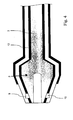
- the conductive core 1 is covered, protected and insulated by a flexible tube, generally indicated by 11 in the Figs. 2a, 2b and 3, and preferably made of up to three layers of material.
- the flexible tube 11 is a moulded or extruded tube made of a first semi-conductive layer 12 (at the inside), an insulating layer 13 made of elastomeric material, and a second semi-conductive layer 14 (at the outside).
- the elastomeric material of the insulating layer 13 is preferably a synthetic terpolymer of ethylene, propylene and diene [EPDM]. Additionally, this EPDM may be recycled and is thus friendly for the environment.
- the tube 11 preferably has the same length as the conductive core 1.
- the flexible tube 11 is then prepared for receiving the conductive core 1, as shown at Fig. 3. Therefore, each end of the second semi-conductive layer 14 is removed at a certain distance up to the insulation material 13. At the same time, an internal ring groove 15 is provided at each end in the first semi-conductive layer 12 and partially in the insulating layer 13 of the flexible tube 11. The flexible tube 11 is then radially expanded and the conductive core 1 is slided therein.
- the flexible tube is released over the conductive core 1 in order to obtain a resulting medium voltage interconnection as shown at Fig. 4.
- the flexible tube 11 has now taken the shape of the underlying conductive core 1 and the latter is prevented to move therein owing to the mating external locking ring 9/10 of the conductive core and the internal ring groove 15 of the tube.
- the first semi-conductive layer 12 of the tube is in contact with the metal flexible conductor 2 and the connectors 3/4.
- each end of the so obtained interconnection may then be engaged into an inner side 16 of a conical bushing, generally indicated by an arrow 17, as described above, and mounted in a hole of a wall 18.
- the receiving connector 19 of the bushing 17 is so brought into contact with the electrical connector 3 of the conductive core via its hole 5, whilst the insulating layer 13 of the interconnection is brought into contact with the inner side 16 of the bushing.
- a fixing ring is provided over the conductive core at each end thereof.
- the fixing ring 20 On the left side of the interconnection, the fixing ring 20 abuts against the base 7 of the conical electrical connector 3 covered by the flexible tube and is mechanically fixed (not shown) to the bushing 17.
- a metal flexible protection (not shown) can be mounted on the outside of the tube to take the short-circuit currents.
- the insulating layer of the bushing device may also be a molded elastomeric material, preferably a synthetic terpolymer of ethylene, propylene and diene [EPDM] as for the insulating layer 13 of the flexible tube 11.
- EPDM ethylene, propylene and diene
Landscapes
- Connector Housings Or Holding Contact Members (AREA)
- Coupling Device And Connection With Printed Circuit (AREA)
- Cable Accessories (AREA)
Abstract
Description
- providing an electrical connector mating said receiving connector at each end of a metal conductor, said metal conductor with its two connectors forming a conductive core,
- providing a flexible tube made of at least an insulating layer of elastomeric material and having the same length as said conductive core,
- expanding radially said flexible tube and sliding therein said conductive core, and
- releasing said flexible tube over said conductive core.
- a first semi-conductive layer,
- an insulating layer made of elastomeric material, and
- a second semi-conductive layer.
- providing an external locking ring onto at least one electrical connector of said conductive core, and
- providing into said flexible tube at least one internal ring groove for receiving the locking ring of said electrical connectors when the tube is released over said conductive core.
Claims (16)
- Method to provide a medium voltage interconnection for realizing an electrical connection between a receiving connector of a first equipment station and a receiving connector of a second equipment station,
characterized in that said method comprises the steps of:providing an electrical connector (3, 4) mating said receiving connector (19) at each end of a metal conductor (2), said metal conductor with its two connectors forming a conductive core (1),providing a flexible tube (11) made of at least an insulating layer (13) of elastomeric material,expanding radially said flexible tube and sliding therein said conductive core, andreleasing said flexible tube over said conductive core. - Method according to claim 1, characterized in that it further comprises the steps of:providing said electrical connector (3) with a substantially conical shape of which the base (7) has a diameter relatively larger than the diameter of said metal conductor (2), andconnecting said base to an end of said metal conductor.
- Method according to anyone of claims 1 or 2, characterized in that said method further comprises the step of engaging one end of said flexible tube into an inner side (16) of a conical bushing means (17) made of insulating material and provided with said receiving connector (19) so as to bring the electrical connector (3) of the conductive core (1) into contact with said receiving connector and said insulating layer (13) of said flexible tube (11) into contact with said inner side of said bushing means.
- Method according to anyone of claims 1 to 3 characterized in that it comprises the steps of providing said flexible tube (11) with, coaxially starting from the center:a first semi-conductive layer (12),an insulating layer (13) made of elastomeric material, anda second semi-conductive layer (14).
- Method according to the claims 3 and 4, characterized in that said method further comprises the step of removing partially said second semi-conductive layer (14) at the end of said flexible tube (11) prior to the step of engaging said end of said flexible tube into said bushing means (17).
- Method according to anyone of claims 4 or 5, characterized in that said method comprises the steps of:providing a ring groove into said first semi-conductive layer (12), andproviding a ring groove partially into said insulating layer (13).
- Method according to anyone of claims 1 to 6, characterized in that said method further comprises the steps of:providing an external locking ring (9, 10) onto at least one electrical connector (3, 4) of said conductive core (1), andproviding into said flexible tube (11) at least one internal ring groove (15) for receiving the locking ring of said electrical connector when the tube is released over said conductive core.
- Method according to anyone of claims 1 to 7 characterized in that said flexible tube (11) has the same length as said conductive core (1).
- Medium voltage interconnection characterized in that it is made according to anyone of claims 1 to 8 and adapted to electrically connect a receiving connector of a first equipment station and a receiving connector of a second equipment station, said interconnection comprising a conductive core (1) including a metal conductor (2) with, at each end thereof, an electrical connector (3, 4) adapted to mate said receiving connector (15), and a flexible tube (11) having at least an insulating layer (13) made of elastomeric material and covering the whole conductive core.
- Medium voltage interconnection according to claim 9, characterized in that said elastomeric material is a synthetic terpolymer of ethylene, propylene and diene [EPDM].
- Medium voltage interconnection according to claim 9, characterized in that said elastomeric material is a silicone.
- Medium voltage interconnection according to anyone of claims 9 to 11, characterized in that said electrical connector (3) has a substantially conical shape of which the base (7) is connected to said metal conductor (2), said base having a diameter relatively larger than the diameter of said metal conductor.
- Medium voltage interconnection according to claim 12, characterized in that one end of said flexible tube (11) is adapted to be engaged into an inner side (16) of a conical bushing means (17) made of insulating material and provided with said receiving connector (15), the electrical connector (3) of said conductive core (1) being adapted to be brought into electrical contact with said receiving connector, and said insulating layer (13) of said flexible tube being adapted to be brought into contact with said inner side of said bushing means.
- Medium voltage interconnection according to claim 13, characterized in that said interconnection is provided with a fixing ring (20) located over said conductive core (1) and over said flexible tube (11), said fixing ring being adapted to abut against the base (7) of the conical electrical connector (3) and to be fixed to said bushing means (17).
- Medium voltage interconnection according to anyone of claims 9 to 14, characterized in that said flexible tube (11) is a multi-layer tube comprising, coaxially starting from the center, a first semi-conductive layer (12), an insulating layer (13) made of elastomeric material, and a second semi5 conductive layer (14).
- Medium voltage interconnection according to anyone of claims 9 to 15, characterized in that the electrical connector (3, 4) of said conductive core (1) is provided with an external locking ring (9, 10) mating in an internal ring groove (15) in the insulating layer (13) of said flexible tube (11).
Priority Applications (1)
| Application Number | Priority Date | Filing Date | Title |
|---|---|---|---|
| EP20010400775 EP1146601B1 (en) | 2000-04-13 | 2001-03-26 | Flexible medium voltage interconnection and method to obtain same |
Applications Claiming Priority (3)
| Application Number | Priority Date | Filing Date | Title |
|---|---|---|---|
| EP00401045 | 2000-04-13 | ||
| EP00401045A EP1146600A1 (en) | 2000-04-13 | 2000-04-13 | Flexible medium voltage interconnection and method to obtain same |
| EP20010400775 EP1146601B1 (en) | 2000-04-13 | 2001-03-26 | Flexible medium voltage interconnection and method to obtain same |
Publications (3)
| Publication Number | Publication Date |
|---|---|
| EP1146601A2 true EP1146601A2 (en) | 2001-10-17 |
| EP1146601A3 EP1146601A3 (en) | 2005-04-13 |
| EP1146601B1 EP1146601B1 (en) | 2006-08-16 |
Family
ID=26073461
Family Applications (1)
| Application Number | Title | Priority Date | Filing Date |
|---|---|---|---|
| EP20010400775 Expired - Lifetime EP1146601B1 (en) | 2000-04-13 | 2001-03-26 | Flexible medium voltage interconnection and method to obtain same |
Country Status (1)
| Country | Link |
|---|---|
| EP (1) | EP1146601B1 (en) |
Family Cites Families (7)
| Publication number | Priority date | Publication date | Assignee | Title |
|---|---|---|---|---|
| US3708610A (en) * | 1971-09-08 | 1973-01-02 | Methode Mfg Corp | Non-delaminating bus assembly for electronic systems and method of forming same |
| US3853375A (en) * | 1972-12-15 | 1974-12-10 | Esco Mfg Co | Electrical connector apparatus disconnectable link assembly |
| US3937995A (en) * | 1974-12-05 | 1976-02-10 | Palmer Industries Ltd. | High voltage grounding strap |
| US4695926A (en) * | 1986-07-01 | 1987-09-22 | Bell Of Pennsylvania | Encapsulation and insulation of electronic circuit board structures |
| IT1233310B (en) * | 1989-06-09 | 1992-03-26 | Ubalit S P A | METHOD FOR THE CREATION OF INSULATED CONDUCTIVE UNITS ELECTRICALLY CONNECTING ELECTRIC LOADS WITH ELECTRIC SIGNAL GENERATORS AND UNITS OBTAINED BY SUCH METHOD |
| FR2741484B1 (en) * | 1995-11-21 | 1997-12-19 | Silec Liaisons Elec | ELECTRICAL CONNECTION PIECE |
| WO1997043698A1 (en) * | 1996-05-15 | 1997-11-20 | Nippon Zeon Co., Ltd. | Semiconductive foamed roller and its manufacturing method |
-
2001
- 2001-03-26 EP EP20010400775 patent/EP1146601B1/en not_active Expired - Lifetime
Also Published As
| Publication number | Publication date |
|---|---|
| EP1146601B1 (en) | 2006-08-16 |
| EP1146601A3 (en) | 2005-04-13 |
Similar Documents
| Publication | Publication Date | Title |
|---|---|---|
| CA2177436C (en) | Loadbreak separable connector | |
| CA2241553C (en) | High voltage electrical connector with access cavity, and inserts for use therewith | |
| AU618871B2 (en) | Element of a device for realizing a joint of electric cables, joint for electric cables obtained thereby, and covering of the connection between the conductors of electric cables for said joint | |
| US8889989B2 (en) | Elastomeric cable adapters for power transmission cables and cover assemblies and methods including the same | |
| CA2853015C (en) | Electrical connector having cold shrink component | |
| EP0731994B2 (en) | Cable termination | |
| AU2009200542B2 (en) | Apparatus for a Junction Point Between Two Electrical High-Voltage Cables | |
| US9455524B2 (en) | Self-supported jacket seal for high voltage cable accessories | |
| EP0848864A1 (en) | Cable termination | |
| US6808403B2 (en) | Flexible medium voltage interconnection and method to obtain same | |
| JP4615258B2 (en) | Power cable termination connection and assembly method | |
| CN112003041A (en) | Cable connector assembly | |
| US4241004A (en) | High voltage splice | |
| EP1146601B1 (en) | Flexible medium voltage interconnection and method to obtain same | |
| EP3446385B1 (en) | Multiple stress control device for cable accessories and methods and systems including same | |
| US12431700B2 (en) | Cold-shrinkable protective housing and methods including same | |
| EP4383490A1 (en) | Testing assisting device for a cable and method of providing a testing assisting device | |
| CN112886331B (en) | Connector and cable connecting device |
Legal Events
| Date | Code | Title | Description |
|---|---|---|---|
| PUAI | Public reference made under article 153(3) epc to a published international application that has entered the european phase |
Free format text: ORIGINAL CODE: 0009012 |
|
| AK | Designated contracting states |
Kind code of ref document: A2 Designated state(s): AT BE CH CY DE DK ES FI FR GB GR IE IT LI LU MC NL PT SE TR |
|
| AX | Request for extension of the european patent |
Free format text: AL;LT;LV;MK;RO;SI |
|
| PUAL | Search report despatched |
Free format text: ORIGINAL CODE: 0009013 |
|
| AK | Designated contracting states |
Kind code of ref document: A3 Designated state(s): AT BE CH CY DE DK ES FI FR GB GR IE IT LI LU MC NL PT SE TR |
|
| AX | Request for extension of the european patent |
Extension state: AL LT LV MK RO SI |
|
| 17P | Request for examination filed |
Effective date: 20051013 |
|
| AKX | Designation fees paid |
Designated state(s): AT BE CH CY DE DK ES FI FR GB GR IE IT LI LU MC NL PT SE TR |
|
| GRAP | Despatch of communication of intention to grant a patent |
Free format text: ORIGINAL CODE: EPIDOSNIGR1 |
|
| GRAS | Grant fee paid |
Free format text: ORIGINAL CODE: EPIDOSNIGR3 |
|
| GRAA | (expected) grant |
Free format text: ORIGINAL CODE: 0009210 |
|
| AK | Designated contracting states |
Kind code of ref document: B1 Designated state(s): AT BE CH CY DE DK ES FI FR GB GR IE IT LI LU MC NL PT SE TR |
|
| PG25 | Lapsed in a contracting state [announced via postgrant information from national office to epo] |
Ref country code: IT Free format text: LAPSE BECAUSE OF FAILURE TO SUBMIT A TRANSLATION OF THE DESCRIPTION OR TO PAY THE FEE WITHIN THE PRESCRIBED TIME-LIMIT;WARNING: LAPSES OF ITALIAN PATENTS WITH EFFECTIVE DATE BEFORE 2007 MAY HAVE OCCURRED AT ANY TIME BEFORE 2007. THE CORRECT EFFECTIVE DATE MAY BE DIFFERENT FROM THE ONE RECORDED. Effective date: 20060816 Ref country code: AT Free format text: LAPSE BECAUSE OF FAILURE TO SUBMIT A TRANSLATION OF THE DESCRIPTION OR TO PAY THE FEE WITHIN THE PRESCRIBED TIME-LIMIT Effective date: 20060816 Ref country code: CH Free format text: LAPSE BECAUSE OF FAILURE TO SUBMIT A TRANSLATION OF THE DESCRIPTION OR TO PAY THE FEE WITHIN THE PRESCRIBED TIME-LIMIT Effective date: 20060816 Ref country code: LI Free format text: LAPSE BECAUSE OF FAILURE TO SUBMIT A TRANSLATION OF THE DESCRIPTION OR TO PAY THE FEE WITHIN THE PRESCRIBED TIME-LIMIT Effective date: 20060816 Ref country code: FI Free format text: LAPSE BECAUSE OF FAILURE TO SUBMIT A TRANSLATION OF THE DESCRIPTION OR TO PAY THE FEE WITHIN THE PRESCRIBED TIME-LIMIT Effective date: 20060816 Ref country code: NL Free format text: LAPSE BECAUSE OF FAILURE TO SUBMIT A TRANSLATION OF THE DESCRIPTION OR TO PAY THE FEE WITHIN THE PRESCRIBED TIME-LIMIT Effective date: 20060816 |
|
| REG | Reference to a national code |
Ref country code: GB Ref legal event code: FG4D |
|
| REG | Reference to a national code |
Ref country code: CH Ref legal event code: EP |
|
| REG | Reference to a national code |
Ref country code: IE Ref legal event code: FG4D |
|
| REF | Corresponds to: |
Ref document number: 60122232 Country of ref document: DE Date of ref document: 20060928 Kind code of ref document: P |
|
| PG25 | Lapsed in a contracting state [announced via postgrant information from national office to epo] |
Ref country code: SE Free format text: LAPSE BECAUSE OF FAILURE TO SUBMIT A TRANSLATION OF THE DESCRIPTION OR TO PAY THE FEE WITHIN THE PRESCRIBED TIME-LIMIT Effective date: 20061116 Ref country code: DK Free format text: LAPSE BECAUSE OF FAILURE TO SUBMIT A TRANSLATION OF THE DESCRIPTION OR TO PAY THE FEE WITHIN THE PRESCRIBED TIME-LIMIT Effective date: 20061116 |
|
| NLV1 | Nl: lapsed or annulled due to failure to fulfill the requirements of art. 29p and 29m of the patents act | ||
| ET | Fr: translation filed | ||
| REG | Reference to a national code |
Ref country code: CH Ref legal event code: PL |
|
| REG | Reference to a national code |
Ref country code: ES Ref legal event code: FG2A Ref document number: 2269321 Country of ref document: ES Kind code of ref document: T3 |
|
| PLBE | No opposition filed within time limit |
Free format text: ORIGINAL CODE: 0009261 |
|
| STAA | Information on the status of an ep patent application or granted ep patent |
Free format text: STATUS: NO OPPOSITION FILED WITHIN TIME LIMIT |
|
| 26N | No opposition filed |
Effective date: 20070518 |
|
| PG25 | Lapsed in a contracting state [announced via postgrant information from national office to epo] |
Ref country code: MC Free format text: LAPSE BECAUSE OF NON-PAYMENT OF DUE FEES Effective date: 20070331 Ref country code: IE Free format text: LAPSE BECAUSE OF NON-PAYMENT OF DUE FEES Effective date: 20070326 |
|
| PG25 | Lapsed in a contracting state [announced via postgrant information from national office to epo] |
Ref country code: GR Free format text: LAPSE BECAUSE OF FAILURE TO SUBMIT A TRANSLATION OF THE DESCRIPTION OR TO PAY THE FEE WITHIN THE PRESCRIBED TIME-LIMIT Effective date: 20061117 |
|
| PGFP | Annual fee paid to national office [announced via postgrant information from national office to epo] |
Ref country code: ES Payment date: 20080328 Year of fee payment: 8 |
|
| PGFP | Annual fee paid to national office [announced via postgrant information from national office to epo] |
Ref country code: GB Payment date: 20080320 Year of fee payment: 8 Ref country code: IT Payment date: 20080326 Year of fee payment: 8 |
|
| PGFP | Annual fee paid to national office [announced via postgrant information from national office to epo] |
Ref country code: DE Payment date: 20080321 Year of fee payment: 8 Ref country code: FR Payment date: 20080314 Year of fee payment: 8 |
|
| PGFP | Annual fee paid to national office [announced via postgrant information from national office to epo] |
Ref country code: BE Payment date: 20080430 Year of fee payment: 8 |
|
| PG25 | Lapsed in a contracting state [announced via postgrant information from national office to epo] |
Ref country code: LU Free format text: LAPSE BECAUSE OF NON-PAYMENT OF DUE FEES Effective date: 20070326 Ref country code: CY Free format text: LAPSE BECAUSE OF FAILURE TO SUBMIT A TRANSLATION OF THE DESCRIPTION OR TO PAY THE FEE WITHIN THE PRESCRIBED TIME-LIMIT Effective date: 20060816 |
|
| BERE | Be: lapsed |
Owner name: *NEXANS Effective date: 20090331 |
|
| PG25 | Lapsed in a contracting state [announced via postgrant information from national office to epo] |
Ref country code: TR Free format text: LAPSE BECAUSE OF FAILURE TO SUBMIT A TRANSLATION OF THE DESCRIPTION OR TO PAY THE FEE WITHIN THE PRESCRIBED TIME-LIMIT Effective date: 20060816 |
|
| GBPC | Gb: european patent ceased through non-payment of renewal fee |
Effective date: 20090326 |
|
| REG | Reference to a national code |
Ref country code: FR Ref legal event code: ST Effective date: 20091130 |
|
| PG25 | Lapsed in a contracting state [announced via postgrant information from national office to epo] |
Ref country code: DE Free format text: LAPSE BECAUSE OF NON-PAYMENT OF DUE FEES Effective date: 20091001 |
|
| PG25 | Lapsed in a contracting state [announced via postgrant information from national office to epo] |
Ref country code: BE Free format text: LAPSE BECAUSE OF NON-PAYMENT OF DUE FEES Effective date: 20090331 |
|
| PG25 | Lapsed in a contracting state [announced via postgrant information from national office to epo] |
Ref country code: FR Free format text: LAPSE BECAUSE OF NON-PAYMENT OF DUE FEES Effective date: 20091123 Ref country code: GB Free format text: LAPSE BECAUSE OF NON-PAYMENT OF DUE FEES Effective date: 20090326 |
|
| REG | Reference to a national code |
Ref country code: ES Ref legal event code: FD2A Effective date: 20090327 |
|
| PG25 | Lapsed in a contracting state [announced via postgrant information from national office to epo] |
Ref country code: ES Free format text: LAPSE BECAUSE OF NON-PAYMENT OF DUE FEES Effective date: 20090327 |
|
| PG25 | Lapsed in a contracting state [announced via postgrant information from national office to epo] |
Ref country code: IT Free format text: LAPSE BECAUSE OF NON-PAYMENT OF DUE FEES Effective date: 20090326 |
|
| PG25 | Lapsed in a contracting state [announced via postgrant information from national office to epo] |
Ref country code: PT Free format text: LAPSE BECAUSE OF FAILURE TO SUBMIT A TRANSLATION OF THE DESCRIPTION OR TO PAY THE FEE WITHIN THE PRESCRIBED TIME-LIMIT Effective date: 20060816 |