EP1146537A1 - High pressure discharge lamp arc tube and method of producing the same - Google Patents
High pressure discharge lamp arc tube and method of producing the same Download PDFInfo
- Publication number
- EP1146537A1 EP1146537A1 EP00966444A EP00966444A EP1146537A1 EP 1146537 A1 EP1146537 A1 EP 1146537A1 EP 00966444 A EP00966444 A EP 00966444A EP 00966444 A EP00966444 A EP 00966444A EP 1146537 A1 EP1146537 A1 EP 1146537A1
- Authority
- EP
- European Patent Office
- Prior art keywords
- capillaries
- center body
- capillary
- alumina
- chamber
- Prior art date
- Legal status (The legal status is an assumption and is not a legal conclusion. Google has not performed a legal analysis and makes no representation as to the accuracy of the status listed.)
- Granted
Links
Images
Classifications
-
- H—ELECTRICITY
- H01—ELECTRIC ELEMENTS
- H01J—ELECTRIC DISCHARGE TUBES OR DISCHARGE LAMPS
- H01J61/00—Gas-discharge or vapour-discharge lamps
- H01J61/02—Details
- H01J61/36—Seals between parts of vessels; Seals for leading-in conductors; Leading-in conductors
- H01J61/361—Seals between parts of vessel
-
- H—ELECTRICITY
- H01—ELECTRIC ELEMENTS
- H01J—ELECTRIC DISCHARGE TUBES OR DISCHARGE LAMPS
- H01J61/00—Gas-discharge or vapour-discharge lamps
- H01J61/02—Details
- H01J61/30—Vessels; Containers
- H01J61/302—Vessels; Containers characterised by the material of the vessel
-
- H—ELECTRICITY
- H01—ELECTRIC ELEMENTS
- H01J—ELECTRIC DISCHARGE TUBES OR DISCHARGE LAMPS
- H01J9/00—Apparatus or processes specially adapted for the manufacture, installation, removal, maintenance of electric discharge tubes, discharge lamps, or parts thereof; Recovery of material from discharge tubes or lamps
- H01J9/24—Manufacture or joining of vessels, leading-in conductors or bases
- H01J9/26—Sealing together parts of vessels
- H01J9/265—Sealing together parts of vessels specially adapted for gas-discharge tubes or lamps
- H01J9/266—Sealing together parts of vessels specially adapted for gas-discharge tubes or lamps specially adapted for gas-discharge lamps
-
- C—CHEMISTRY; METALLURGY
- C04—CEMENTS; CONCRETE; ARTIFICIAL STONE; CERAMICS; REFRACTORIES
- C04B—LIME, MAGNESIA; SLAG; CEMENTS; COMPOSITIONS THEREOF, e.g. MORTARS, CONCRETE OR LIKE BUILDING MATERIALS; ARTIFICIAL STONE; CERAMICS; REFRACTORIES; TREATMENT OF NATURAL STONE
- C04B2235/00—Aspects relating to ceramic starting mixtures or sintered ceramic products
- C04B2235/65—Aspects relating to heat treatments of ceramic bodies such as green ceramics or pre-sintered ceramics, e.g. burning, sintering or melting processes
- C04B2235/658—Atmosphere during thermal treatment
- C04B2235/6582—Hydrogen containing atmosphere
-
- C—CHEMISTRY; METALLURGY
- C04—CEMENTS; CONCRETE; ARTIFICIAL STONE; CERAMICS; REFRACTORIES
- C04B—LIME, MAGNESIA; SLAG; CEMENTS; COMPOSITIONS THEREOF, e.g. MORTARS, CONCRETE OR LIKE BUILDING MATERIALS; ARTIFICIAL STONE; CERAMICS; REFRACTORIES; TREATMENT OF NATURAL STONE
- C04B2235/00—Aspects relating to ceramic starting mixtures or sintered ceramic products
- C04B2235/70—Aspects relating to sintered or melt-casted ceramic products
- C04B2235/74—Physical characteristics
- C04B2235/78—Grain sizes and shapes, product microstructures, e.g. acicular grains, equiaxed grains, platelet-structures
- C04B2235/786—Micrometer sized grains, i.e. from 1 to 100 micron
-
- C—CHEMISTRY; METALLURGY
- C04—CEMENTS; CONCRETE; ARTIFICIAL STONE; CERAMICS; REFRACTORIES
- C04B—LIME, MAGNESIA; SLAG; CEMENTS; COMPOSITIONS THEREOF, e.g. MORTARS, CONCRETE OR LIKE BUILDING MATERIALS; ARTIFICIAL STONE; CERAMICS; REFRACTORIES; TREATMENT OF NATURAL STONE
- C04B2235/00—Aspects relating to ceramic starting mixtures or sintered ceramic products
- C04B2235/70—Aspects relating to sintered or melt-casted ceramic products
- C04B2235/94—Products characterised by their shape
Definitions
- the present invention relates to a discharge vessel or chamber for a high-intensity discharge lamp andparticularly, to a discharge vessel or chamber having a capillary at each end thereof for holding en electrode and a method of fabricating the same.
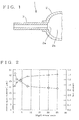
- Ceramic made discharge vessel or chambers for high-intensity discharge lamps are generally classified into an integral type where the center body defining a discharge space and the capillary for holding an electrode are formed integral with each other and an assembly type which comprise the body and the capillary fabricated separately as two different components and assembled together. In either type, as shown in the explanatory cross sectional view of Fig.
- an electrode is fabricated by an electrode material 12 with a discharge electrode 14 made of tungsten or the like joining to the distal end of a current conductor 13 made of niobium, molybdenum, or the like and inserted into capillary 11 made of an alumina based ceramic material or an alumina material before the gap between the electrode and the capillary is sealed air-tightly with a frit sealer 15 of a glass material.
- the discharge vessel or chamber is then baked at its body and capillary simultaneously at a proper temperature.
- a discharge vessel or chamber for a high-intensity discharge lamp having a center body arranged providing a discharge space therein and two capillaries provided for shutting up both end openings of the body and accepting a pair of electrodes respectively is provided wherein the center body and the capillaries are made of an alumina material or an alumina-based ceramic material and the average diameter of alumina grains in the capillaries ranges from 10 micrometers to 25 micrometers.
- the discharge vessel or chamber according to claim 1 may be modified in which the capillaries contain an amount of magnesium oxide, yttrium oxide, zirconium oxide, scandium oxide, lanthanum oxide, or their combination, 1.5 times greater than that of the center body.
- the discharge vessel or chamber according to claim 1 may be modified in which the center body and the capillaries are made of an alumina-based composition.
- a method of fabricating a discharge vessel or chamber for a which has a center body arranged providing a discharge space therein and two capillaries provided for shutting up both end openings of the body and accepting a pair of electrodes respectively is provided comprising the steps of: forming the center body and the capillaries from an alumina material or an alumina-based ceramic material; and sintering the center body and at least portions of the capillaries at different temperatures.
- Fig. 1 is an explanatory cross sectional view of a electrode section of a discharge vessel or chamber of a high-pressure discharge lamp according to the present invention.
- the discharge vessel or chamber 1 comprises a center body 2 having an opening 2a provided at each end thereof and a discharge space 2b defined therein and a pair of capillaries 3, each inserted into the opening 2a and having a tubular shape for accepting and holding an electrode material (not shown).
- the capillary 3 is doped with an amount of magnesium oxide substantially 20 times greater than that in the body 2 and its average diameter of alumina grains is decreased to as smaller as 19 micrometers than 32 micrometers in the body 2 for increasing the physical strength.
- the doping of magnesium oxide permits the average diameter to be decreased, thus improving the physical strength. Accordingly, the generation of cracks during the installation of the electrode material will be prevented. It is hence unnecessary for the sealing to measure a precise amount of the frit sealer and fill the gap close to the center body with the frit sealer more than hitherto. It is also not needed to increase the thickness of the capillary, thus down-sizing the discharge lamp with much ease.
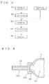
- the dosage of magnesium oxide is not limited to 20 times greater than in the center body but may be within a range of the ratio shown in the diagram of Fig. 2 for the relation between the dosage, the average grain diameter, and the physical strength.
- the capillary 3 is greater in the dosage of magnesium oxide than the center body 2, it can be smaller in the average diameter but higher in the physical strength than the center body 2. If the ratio is not greater than 1.5 times, the physical strength may hardly increase. When the ratio exceeds 25 times, the strength is not increased in proportion with the dosage.
- the dosage is preferably within a range from 1.5 times to 25 times.
- the horizontal axis represents the ratio in the dosage of magnesium oxide of the capillary 3 to the center body while the bend strength is a ratio to the center body.
- the center body 2 and the capillary 3 are made of an alumina material or an alumina-based ceramic material.
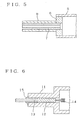
- the procedure starts with forming the capillary 3 at Step 1 (S1). During this forming step, an amount of magnesium oxide, e.g. 20 time greater than of the center body 2, is doped.
- S2 a green form is pre-baked at 1200 °C for three hours under the atmospheric conditions.
- the pre-sintering is followed by inserting at S3 the capillary 3 into the opening 2a of the center body 2 formed separately. Then, the assembly is pre-based at 1200 °C for three hours under the atmospheric conditions at S4. Finally, the same is baked at 1850 °C for three hours under the hydrogen atmosphere at S5.
- the oxide dopant is not limited to magnesium oxide but maybe selected from yttrium oxide, zirconiumoxide, scandium oxide, lanthanum oxide, and their combination. Those like magnesium oxide also permit the diameter of grains to be minimized and the physical strength to be increased.
- the center body 2 and the capillary 3 may not be made of the same composition.
- the capillary 3 may contain a metal material, which is used in the joint of an electrode material, in order to make its characteristic of thermal expansion equal to that of the metal material.
- FIG. 4 is an explanatory cross sectional view of an electrode section showing the second embodiment of the present invention.
- a center body 9 has an opening 9a provided at each of both, left and right, ends of a discharge space 9b thereof.
- Each the opening 9a of the body 9 is shut up with a capillary 10 in which an electrode material (not shown) is inserted and secured by sealing.
- the capillary 10 comprises a cover portion 10a for closing the opening 9a of the body 9 and a capillary portion 10b extending outwardly and vertically from the center of the cover portion 10a.
- Amethod of fabricating the second embodiment comprises the steps of forming the center body 9 and the capillary 10 of an alumina material or an alumina-based ceramic material and after pre-sintering, sintering the center body 9 at 1850 °C.
- the capillary 10 after formed is pre-baked at 1200 °C to 1400 °C. Then, both are joined to each other and baked at 1700°C. The joining is made by the cover portion 10a inserted into the opening 9a and shrunk-on joining to the center body 9.
- the sintering temperature of the center body 9 is 1850 °C and that of the capillary 10 is 1700 °C, i.e. the center body 9 is baked at the higher temperature, the average diameter of alumina grains in the center body 9 can be increased as great as 35 micrometers, hence increasing the permeability of light and improving the optical properties.
- the capillary 10 is baked at the lower temperature and its average diameter of alumina grains can be as small as 25 micrometers.
- the sintering temperature of 1850 °C the physical strength can be increased, for instance, from 29 kg/cm 2 to 38 to 45 kg/cm 2 . This will prevent the generation of cracks on the frit sealer during the sealing of the electrode. If the capillary 10 has an average diameter greater than 25 micrometers, its physical strength may be declined. When lower than 10 micrometers, the other properties including the resistance to corrosion may be degraded.
- the average diameter ranges from 10 to 25 micrometers.
- FIG. 5 illustrates a third embodiment of the present invention.
- a center body 5 of a cylindrical shape has two openings provided in both ends thereof, each the opening shut up with a ring-like plug 6.
- a capillary 7 is inserted into the center hole of the opening.
- a tubular member 8 is fitted onto the capillary 7, thus forming a double-capillary structure.
- the body 5, the plug 6, and the capillary 7 are assembled and joined by a conventional sintering method, such as a shrunk-on method of sintering at 1850 °C, which is based on a difference in the shrinkage.
- a conventional sintering method such as a shrunk-on method of sintering at 1850 °C, which is based on a difference in the shrinkage.
- the tubular member 8 is fitted onto the capillary 7 and subjected to a re-sintering process.
- the tubular member 8 is baked at 1200 °C, fitted onto the capillary 7, and baked again at 1700 °C for shrunk-on joining with the capillary 7.
- the present invention allows the capillary to be improved in the physical strength thus minimizing the generation of cracks during the sealing of the discharge vessel or chamber and also contributing to the down-sizing of the discharge vessel or chamber.
- the present invention according to claim 4 allows the center body and the capillary to be different in the sintering temperature so that the average diameter of grains in the capillary can be smaller than that in the center body. As a result, the physical strength of the capillary can be increased thus preventing the generation of cracks during the sealing with the electrode.
Landscapes
- Engineering & Computer Science (AREA)
- Manufacturing & Machinery (AREA)
- Vessels And Coating Films For Discharge Lamps (AREA)
- Manufacture Of Electron Tubes, Discharge Lamp Vessels, Lead-In Wires, And The Like (AREA)
Abstract
Description
Claims (4)
- A discharge vessel or chamber for a high-intensity discharge lamp having a center body arranged providing a discharge space therein and two capillaries provided for shutting up both end openings of the center body and accepting a pair of electrodes respectively, wherein
the center body and the capillaries are made of an alumina material or an alumina-based ceramic material and the average diameter of alumina grains in the capillaries ranges from 10 micrometers to 25 micrometers. - A discharge vessel or chamber for a high-intensity discharge lamp according to claim 1, wherein the capillaries contain an amount of magnesium oxide, yttrium oxide, zirconium oxide, scandium oxide, lanthanum oxide, or their combination, 1.5 times greater than that of the center body.
- A discharge vessel or chamber for a high-intensity discharge lamp according to claim 1, wherein the center body and the capillaries are made of an alumina-based composition.
- A method of fabricating a discharge vessel or chamber for a high-intensity discharge lamp which has a center body arranged providing a discharge space therein and two capillaries provided for shutting up both end openings of the body and accepting a pair of electrodes respectively, comprising the steps of:forming the center body and the capillaries from an alumina material or an alumina-based ceramic material; andsintering the center body and at least portions of the capillaries at different temperatures.
Applications Claiming Priority (5)
| Application Number | Priority Date | Filing Date | Title |
|---|---|---|---|
| JP29418099 | 1999-10-15 | ||
| JP29418099 | 1999-10-15 | ||
| JP2000306641A JP4613408B2 (en) | 1999-10-15 | 2000-10-05 | Manufacturing method of arc tube for high pressure discharge lamp |
| JP2000306641 | 2000-10-05 | ||
| PCT/JP2000/007086 WO2001027966A1 (en) | 1999-10-15 | 2000-10-12 | High pressure discharge lamp arc tube and method of producing the same |
Publications (3)
| Publication Number | Publication Date |
|---|---|
| EP1146537A1 true EP1146537A1 (en) | 2001-10-17 |
| EP1146537A4 EP1146537A4 (en) | 2006-09-13 |
| EP1146537B1 EP1146537B1 (en) | 2008-12-17 |
Family
ID=26559709
Family Applications (1)
| Application Number | Title | Priority Date | Filing Date |
|---|---|---|---|
| EP00966444A Expired - Lifetime EP1146537B1 (en) | 1999-10-15 | 2000-10-12 | High pressure discharge lamp arc tube and method of producing the same |
Country Status (7)
| Country | Link |
|---|---|
| US (1) | US6969951B1 (en) |
| EP (1) | EP1146537B1 (en) |
| JP (1) | JP4613408B2 (en) |
| CN (1) | CN1218351C (en) |
| CZ (1) | CZ20012192A3 (en) |
| DE (1) | DE60041122D1 (en) |
| WO (1) | WO2001027966A1 (en) |
Cited By (1)
| Publication number | Priority date | Publication date | Assignee | Title |
|---|---|---|---|---|
| EP1363863A4 (en) * | 2000-12-19 | 2007-08-15 | Gen Electric | Method for forming complex ceramic shapes |
Families Citing this family (4)
| Publication number | Priority date | Publication date | Assignee | Title |
|---|---|---|---|---|
| US6873108B2 (en) * | 2001-09-14 | 2005-03-29 | Osram Sylvania Inc. | Monolithic seal for a sapphire metal halide lamp |
| US20100026181A1 (en) * | 2008-08-01 | 2010-02-04 | Osram Sylvania Inc. | Ceramic discharge vessel and method of making same |
| JP2010287555A (en) * | 2009-05-15 | 2010-12-24 | Toshiba Lighting & Technology Corp | High pressure discharge lamp |
| CN103730326A (en) * | 2014-01-07 | 2014-04-16 | 戴建国 | Ceramic nanometer lamp |
Family Cites Families (24)
| Publication number | Priority date | Publication date | Assignee | Title |
|---|---|---|---|---|
| US3311482A (en) * | 1966-01-25 | 1967-03-28 | Emil A Klingler | Sintered transparent bodies of aluminum oxide and method of preparing the same |
| JPS51107683A (en) * | 1975-03-18 | 1976-09-24 | Ngk Insulators Ltd | Taketsushotomeiaruminahatsukokan |
| FR2475533A1 (en) * | 1980-02-08 | 1981-08-14 | Euroceral | PROCESS FOR MANUFACTURING PARTS, IN PARTICULAR TUBES, OF TRANSLUCENT ALUMINA |
| US4285732A (en) * | 1980-03-11 | 1981-08-25 | General Electric Company | Alumina ceramic |
| JPS5823158A (en) * | 1981-08-04 | 1983-02-10 | Ngk Insulators Ltd | Manufacture of ceramic tube for metal vapor electric- discharge lamp |
| JPS5929345A (en) * | 1982-08-10 | 1984-02-16 | Matsushita Electronics Corp | High pressure sodium lamp |
| US5096862A (en) * | 1990-08-09 | 1992-03-17 | Minnesota Mining And Manufacturing Company | Transparent ceramic composite article comprising aluminum oxide and aluminum magnesium oxynitride |
| US5424609A (en) * | 1992-09-08 | 1995-06-13 | U.S. Philips Corporation | High-pressure discharge lamp |
| US5426343A (en) * | 1992-09-16 | 1995-06-20 | Gte Products Corporation | Sealing members for alumina arc tubes and method of making the same |
| EP0609477B1 (en) * | 1993-02-05 | 1999-05-06 | Patent-Treuhand-Gesellschaft für elektrische Glühlampen mbH | Ceramic discharge vessel for high-pressure lamps, method of manufacturing same, and related sealing material |
| EP0657399B1 (en) | 1993-12-10 | 1997-07-16 | Patent-Treuhand-Gesellschaft für elektrische Glühlampen mbH | High-pressure discharge lamp having a ceramic discharge vessel, sintered body suitable therefor, and methods for producing the said sintered body |
| US5487353A (en) * | 1994-02-14 | 1996-01-30 | General Electric Company | Conversion of doped polycrystalline material to single crystal |
| JP3301887B2 (en) * | 1995-02-28 | 2002-07-15 | 京セラ株式会社 | Arc tube for metal vapor discharge lamp |
| JPH10134768A (en) * | 1996-10-25 | 1998-05-22 | Toto Ltd | Discharge lamp |
| JP3399763B2 (en) * | 1996-12-26 | 2003-04-21 | ウシオ電機株式会社 | Ceramic high-pressure mercury discharge lamp for LCD backlight |
| US6020685A (en) * | 1997-06-27 | 2000-02-01 | Osram Sylvania Inc. | Lamp with radially graded cermet feedthrough assembly |
| US5861714A (en) * | 1997-06-27 | 1999-01-19 | Osram Sylvania Inc. | Ceramic envelope device, lamp with such a device, and method of manufacture of such devices |
| EP0960432B1 (en) * | 1997-12-16 | 2004-07-14 | Koninklijke Philips Electronics N.V. | High-pressure discharge lamp |
| US6169366B1 (en) * | 1997-12-24 | 2001-01-02 | Ngk Insulators, Ltd. | High pressure discharge lamp |
| US6126889A (en) * | 1998-02-11 | 2000-10-03 | General Electric Company | Process of preparing monolithic seal for sapphire CMH lamp |
| JPH11283569A (en) * | 1998-03-30 | 1999-10-15 | Ngk Insulators Ltd | High pressure discharge lamp |
| US6635993B1 (en) * | 1998-08-26 | 2003-10-21 | Ngk Insulators, Ltd. | Joined bodies, high-pressure discharge lamps and a method for manufacturing the same |
| US6004503A (en) * | 1998-10-02 | 1999-12-21 | Osram Sylvania Inc. | Method of making a ceramic arc tube for metal halide lamps |
| DE10038841C1 (en) * | 2000-08-04 | 2001-12-20 | Heraeus Gmbh W C | Silicon dioxide glass bulb used in a high power discharge lamp has a current duct made from a gas-tight composite material consisting of a precious metal and silicon dioxide |
-
2000
- 2000-10-05 JP JP2000306641A patent/JP4613408B2/en not_active Expired - Fee Related
- 2000-10-12 DE DE60041122T patent/DE60041122D1/en not_active Expired - Lifetime
- 2000-10-12 US US09/857,540 patent/US6969951B1/en not_active Expired - Fee Related
- 2000-10-12 CZ CZ20012192A patent/CZ20012192A3/en unknown
- 2000-10-12 WO PCT/JP2000/007086 patent/WO2001027966A1/en not_active Ceased
- 2000-10-12 CN CN00803811.2A patent/CN1218351C/en not_active Expired - Fee Related
- 2000-10-12 EP EP00966444A patent/EP1146537B1/en not_active Expired - Lifetime
Cited By (1)
| Publication number | Priority date | Publication date | Assignee | Title |
|---|---|---|---|---|
| EP1363863A4 (en) * | 2000-12-19 | 2007-08-15 | Gen Electric | Method for forming complex ceramic shapes |
Also Published As
| Publication number | Publication date |
|---|---|
| DE60041122D1 (en) | 2009-01-29 |
| EP1146537B1 (en) | 2008-12-17 |
| JP2001185085A (en) | 2001-07-06 |
| US6969951B1 (en) | 2005-11-29 |
| CN1340206A (en) | 2002-03-13 |
| JP4613408B2 (en) | 2011-01-19 |
| WO2001027966A1 (en) | 2001-04-19 |
| EP1146537A4 (en) | 2006-09-13 |
| CN1218351C (en) | 2005-09-07 |
| CZ20012192A3 (en) | 2001-11-14 |
Similar Documents
| Publication | Publication Date | Title |
|---|---|---|
| JP3019968B2 (en) | High pressure discharge lamp and manufacturing method thereof | |
| US5424608A (en) | High-pressure discharge lamp with ceramic discharge vessel | |
| CA1214491A (en) | Direct seal between niobium and ceramics | |
| EP0751549B1 (en) | High pressure discharge lamp and production method thereof | |
| US6274982B1 (en) | Monolithic seal for sapphire CMH lamp | |
| EP1568066B1 (en) | High-pressure discharge lamp, and method of manufacture thereof | |
| JP3465193B2 (en) | High pressure discharge lamp | |
| US5404077A (en) | High-pressure discharge lamp | |
| US6528945B2 (en) | Seal for ceramic metal halide discharge lamp | |
| US5783907A (en) | High pressure discharge lamps with sealing members | |
| US4800320A (en) | Discharge tube for a high pressure metal vapor discharge lamp and a method of manufacturing the same | |
| EP2122663B1 (en) | High-pressure discharge lamp having a ceramic discharge vessel | |
| EP1759403B1 (en) | Ceramic metal halide discharge lamp | |
| US20080211410A1 (en) | High intensity discharge lamp having compliant seal | |
| EP1146537B1 (en) | High pressure discharge lamp arc tube and method of producing the same | |
| GB2366908A (en) | Metal halide lamp with ceramic discharge vessel | |
| EP0960432B1 (en) | High-pressure discharge lamp | |
| US20090267513A1 (en) | High-Pressure Discharge Lamp With Ceramic Discharge Vessel |
Legal Events
| Date | Code | Title | Description |
|---|---|---|---|
| PUAI | Public reference made under article 153(3) epc to a published international application that has entered the european phase |
Free format text: ORIGINAL CODE: 0009012 |
|
| 17P | Request for examination filed |
Effective date: 20010621 |
|
| AK | Designated contracting states |
Kind code of ref document: A1 Designated state(s): AT BE CH CY DE DK ES FI FR GB GR IE IT LI LU MC NL PT SE |
|
| RBV | Designated contracting states (corrected) |
Designated state(s): BE DE FR GB NL |
|
| A4 | Supplementary search report drawn up and despatched |
Effective date: 20060817 |
|
| RIC1 | Information provided on ipc code assigned before grant |
Ipc: H01J 61/82 20060101ALI20060810BHEP Ipc: H01J 61/30 20060101AFI20060810BHEP Ipc: C04B 35/115 20060101ALI20060810BHEP |
|
| 17Q | First examination report despatched |
Effective date: 20061206 |
|
| 17Q | First examination report despatched |
Effective date: 20061206 |
|
| GRAP | Despatch of communication of intention to grant a patent |
Free format text: ORIGINAL CODE: EPIDOSNIGR1 |
|
| GRAS | Grant fee paid |
Free format text: ORIGINAL CODE: EPIDOSNIGR3 |
|
| GRAA | (expected) grant |
Free format text: ORIGINAL CODE: 0009210 |
|
| AK | Designated contracting states |
Kind code of ref document: B1 Designated state(s): BE DE FR GB NL |
|
| REG | Reference to a national code |
Ref country code: GB Ref legal event code: FG4D |
|
| REF | Corresponds to: |
Ref document number: 60041122 Country of ref document: DE Date of ref document: 20090129 Kind code of ref document: P |
|
| PG25 | Lapsed in a contracting state [announced via postgrant information from national office to epo] |
Ref country code: BE Free format text: LAPSE BECAUSE OF FAILURE TO SUBMIT A TRANSLATION OF THE DESCRIPTION OR TO PAY THE FEE WITHIN THE PRESCRIBED TIME-LIMIT Effective date: 20081217 |
|
| PLBE | No opposition filed within time limit |
Free format text: ORIGINAL CODE: 0009261 |
|
| STAA | Information on the status of an ep patent application or granted ep patent |
Free format text: STATUS: NO OPPOSITION FILED WITHIN TIME LIMIT |
|
| 26N | No opposition filed |
Effective date: 20090918 |
|
| REG | Reference to a national code |
Ref country code: FR Ref legal event code: ST Effective date: 20100630 |
|
| PG25 | Lapsed in a contracting state [announced via postgrant information from national office to epo] |
Ref country code: FR Free format text: LAPSE BECAUSE OF NON-PAYMENT OF DUE FEES Effective date: 20091102 |
|
| PG25 | Lapsed in a contracting state [announced via postgrant information from national office to epo] |
Ref country code: GB Free format text: LAPSE BECAUSE OF NON-PAYMENT OF DUE FEES Effective date: 20091012 |
|
| PGFP | Annual fee paid to national office [announced via postgrant information from national office to epo] |
Ref country code: DE Payment date: 20121031 Year of fee payment: 13 |
|
| PGFP | Annual fee paid to national office [announced via postgrant information from national office to epo] |
Ref country code: NL Payment date: 20121008 Year of fee payment: 13 |
|
| REG | Reference to a national code |
Ref country code: NL Ref legal event code: V1 Effective date: 20140501 |
|
| REG | Reference to a national code |
Ref country code: DE Ref legal event code: R119 Ref document number: 60041122 Country of ref document: DE Effective date: 20140501 |
|
| PG25 | Lapsed in a contracting state [announced via postgrant information from national office to epo] |
Ref country code: NL Free format text: LAPSE BECAUSE OF NON-PAYMENT OF DUE FEES Effective date: 20140501 Ref country code: DE Free format text: LAPSE BECAUSE OF NON-PAYMENT OF DUE FEES Effective date: 20140501 |