EP1146513A2 - Data recording and reproducing - Google Patents
Data recording and reproducing Download PDFInfo
- Publication number
- EP1146513A2 EP1146513A2 EP01303470A EP01303470A EP1146513A2 EP 1146513 A2 EP1146513 A2 EP 1146513A2 EP 01303470 A EP01303470 A EP 01303470A EP 01303470 A EP01303470 A EP 01303470A EP 1146513 A2 EP1146513 A2 EP 1146513A2
- Authority
- EP
- European Patent Office
- Prior art keywords
- data
- linking
- block
- run
- written
- Prior art date
- Legal status (The legal status is an assumption and is not a legal conclusion. Google has not performed a legal analysis and makes no representation as to the accuracy of the status listed.)
- Withdrawn
Links
Images




Classifications
-
- G—PHYSICS
- G11—INFORMATION STORAGE
- G11B—INFORMATION STORAGE BASED ON RELATIVE MOVEMENT BETWEEN RECORD CARRIER AND TRANSDUCER
- G11B27/00—Editing; Indexing; Addressing; Timing or synchronising; Monitoring; Measuring tape travel
- G11B27/10—Indexing; Addressing; Timing or synchronising; Measuring tape travel
- G11B27/19—Indexing; Addressing; Timing or synchronising; Measuring tape travel by using information detectable on the record carrier
- G11B27/28—Indexing; Addressing; Timing or synchronising; Measuring tape travel by using information detectable on the record carrier by using information signals recorded by the same method as the main recording
- G11B27/32—Indexing; Addressing; Timing or synchronising; Measuring tape travel by using information detectable on the record carrier by using information signals recorded by the same method as the main recording on separate auxiliary tracks of the same or an auxiliary record carrier
- G11B27/327—Table of contents
- G11B27/329—Table of contents on a disc [VTOC]
-
- G—PHYSICS
- G11—INFORMATION STORAGE
- G11B—INFORMATION STORAGE BASED ON RELATIVE MOVEMENT BETWEEN RECORD CARRIER AND TRANSDUCER
- G11B20/00—Signal processing not specific to the method of recording or reproducing; Circuits therefor
- G11B20/10—Digital recording or reproducing
-
- G—PHYSICS
- G11—INFORMATION STORAGE
- G11B—INFORMATION STORAGE BASED ON RELATIVE MOVEMENT BETWEEN RECORD CARRIER AND TRANSDUCER
- G11B20/00—Signal processing not specific to the method of recording or reproducing; Circuits therefor
- G11B20/10—Digital recording or reproducing
- G11B20/12—Formatting, e.g. arrangement of data block or words on the record carriers
-
- G—PHYSICS
- G11—INFORMATION STORAGE
- G11B—INFORMATION STORAGE BASED ON RELATIVE MOVEMENT BETWEEN RECORD CARRIER AND TRANSDUCER
- G11B20/00—Signal processing not specific to the method of recording or reproducing; Circuits therefor
- G11B20/10—Digital recording or reproducing
- G11B20/12—Formatting, e.g. arrangement of data block or words on the record carriers
- G11B20/1217—Formatting, e.g. arrangement of data block or words on the record carriers on discs
-
- G—PHYSICS
- G11—INFORMATION STORAGE
- G11B—INFORMATION STORAGE BASED ON RELATIVE MOVEMENT BETWEEN RECORD CARRIER AND TRANSDUCER
- G11B27/00—Editing; Indexing; Addressing; Timing or synchronising; Monitoring; Measuring tape travel
- G11B27/10—Indexing; Addressing; Timing or synchronising; Measuring tape travel
- G11B27/19—Indexing; Addressing; Timing or synchronising; Measuring tape travel by using information detectable on the record carrier
- G11B27/24—Indexing; Addressing; Timing or synchronising; Measuring tape travel by using information detectable on the record carrier by sensing features on the record carrier other than the transducing track ; sensing signals or marks recorded by another method than the main recording
-
- G—PHYSICS
- G11—INFORMATION STORAGE
- G11B—INFORMATION STORAGE BASED ON RELATIVE MOVEMENT BETWEEN RECORD CARRIER AND TRANSDUCER
- G11B27/00—Editing; Indexing; Addressing; Timing or synchronising; Monitoring; Measuring tape travel
- G11B27/10—Indexing; Addressing; Timing or synchronising; Measuring tape travel
- G11B27/19—Indexing; Addressing; Timing or synchronising; Measuring tape travel by using information detectable on the record carrier
- G11B27/28—Indexing; Addressing; Timing or synchronising; Measuring tape travel by using information detectable on the record carrier by using information signals recorded by the same method as the main recording
- G11B27/30—Indexing; Addressing; Timing or synchronising; Measuring tape travel by using information detectable on the record carrier by using information signals recorded by the same method as the main recording on the same track as the main recording
- G11B27/3027—Indexing; Addressing; Timing or synchronising; Measuring tape travel by using information detectable on the record carrier by using information signals recorded by the same method as the main recording on the same track as the main recording used signal is digitally coded
- G11B27/3063—Subcodes
-
- G—PHYSICS
- G11—INFORMATION STORAGE
- G11B—INFORMATION STORAGE BASED ON RELATIVE MOVEMENT BETWEEN RECORD CARRIER AND TRANSDUCER
- G11B20/00—Signal processing not specific to the method of recording or reproducing; Circuits therefor
- G11B20/10—Digital recording or reproducing
- G11B20/12—Formatting, e.g. arrangement of data block or words on the record carriers
- G11B2020/1264—Formatting, e.g. arrangement of data block or words on the record carriers wherein the formatting concerns a specific kind of data
- G11B2020/1265—Control data, system data or management information, i.e. data used to access or process user data
- G11B2020/1277—Control data, system data or management information, i.e. data used to access or process user data for managing gaps between two recordings, e.g. control data in linking areas, run-in or run-out fields, guard or buffer zones
-
- G—PHYSICS
- G11—INFORMATION STORAGE
- G11B—INFORMATION STORAGE BASED ON RELATIVE MOVEMENT BETWEEN RECORD CARRIER AND TRANSDUCER
- G11B2220/00—Record carriers by type
- G11B2220/20—Disc-shaped record carriers
- G11B2220/21—Disc-shaped record carriers characterised in that the disc is of read-only, rewritable, or recordable type
- G11B2220/215—Recordable discs
-
- G—PHYSICS
- G11—INFORMATION STORAGE
- G11B—INFORMATION STORAGE BASED ON RELATIVE MOVEMENT BETWEEN RECORD CARRIER AND TRANSDUCER
- G11B2220/00—Record carriers by type
- G11B2220/20—Disc-shaped record carriers
- G11B2220/21—Disc-shaped record carriers characterised in that the disc is of read-only, rewritable, or recordable type
- G11B2220/215—Recordable discs
- G11B2220/216—Rewritable discs
-
- G—PHYSICS
- G11—INFORMATION STORAGE
- G11B—INFORMATION STORAGE BASED ON RELATIVE MOVEMENT BETWEEN RECORD CARRIER AND TRANSDUCER
- G11B2220/00—Record carriers by type
- G11B2220/20—Disc-shaped record carriers
- G11B2220/21—Disc-shaped record carriers characterised in that the disc is of read-only, rewritable, or recordable type
- G11B2220/215—Recordable discs
- G11B2220/218—Write-once discs
-
- G—PHYSICS
- G11—INFORMATION STORAGE
- G11B—INFORMATION STORAGE BASED ON RELATIVE MOVEMENT BETWEEN RECORD CARRIER AND TRANSDUCER
- G11B2220/00—Record carriers by type
- G11B2220/20—Disc-shaped record carriers
- G11B2220/25—Disc-shaped record carriers characterised in that the disc is based on a specific recording technology
- G11B2220/2537—Optical discs
-
- G—PHYSICS
- G11—INFORMATION STORAGE
- G11B—INFORMATION STORAGE BASED ON RELATIVE MOVEMENT BETWEEN RECORD CARRIER AND TRANSDUCER
- G11B2220/00—Record carriers by type
- G11B2220/20—Disc-shaped record carriers
- G11B2220/25—Disc-shaped record carriers characterised in that the disc is based on a specific recording technology
- G11B2220/2537—Optical discs
- G11B2220/2545—CDs
-
- G—PHYSICS
- G11—INFORMATION STORAGE
- G11B—INFORMATION STORAGE BASED ON RELATIVE MOVEMENT BETWEEN RECORD CARRIER AND TRANSDUCER
- G11B27/00—Editing; Indexing; Addressing; Timing or synchronising; Monitoring; Measuring tape travel
- G11B27/10—Indexing; Addressing; Timing or synchronising; Measuring tape travel
- G11B27/19—Indexing; Addressing; Timing or synchronising; Measuring tape travel by using information detectable on the record carrier
- G11B27/28—Indexing; Addressing; Timing or synchronising; Measuring tape travel by using information detectable on the record carrier by using information signals recorded by the same method as the main recording
- G11B27/30—Indexing; Addressing; Timing or synchronising; Measuring tape travel by using information detectable on the record carrier by using information signals recorded by the same method as the main recording on the same track as the main recording
- G11B27/3027—Indexing; Addressing; Timing or synchronising; Measuring tape travel by using information detectable on the record carrier by using information signals recorded by the same method as the main recording on the same track as the main recording used signal is digitally coded
Definitions
- the present invention relates to a data reproducing method and apparatus, and a data recording method and apparatus.
- An embodiment of the present invention relates to a data reproducing method and apparatus for reading data written in a data recording area of a recording medium while linking the data in predetermined units, and to a data recording method and apparatus for writing data to a data recording area of a recoding medium while linking the data in predetermined units.
- CD compact disc
- the CD system has initially been developed as a recording and playback system for digital audio data. As this technology has been accepted very widely, a wide variety of CD systems have so far been proposed for various applications.
- CD-ROM read-only memory
- CD-R recordable
- CD-RW rewritable optical disc
- Data is recorded to the CD-R and CD-RW by the so-called "Track At Once” method by which data is written in units of a track, and the so-called “Packet Writing” method by which data is written in units of a packet which is a smaller unit than the track.
- a plurality of data linking blocks is provided between tracks or between packets, each being a unit in which data is continuously recorded, according to a predetermined linking rule. That is, in case data is recorded by the "Track At Once” method or “Packet Writing” method, it will be written with a plurality of data linking blocks appended at each unit of data which is to be continuously written.
- the plurality of data linking blocks is appended between tracks or packets.
- the CD-R and CD-RW adopt a convolution type cross coding method called "CIRC (cross interleave Reed-Solomon code)" and a data discontinuity takes place at a linking position because of the CIRC interleaving. That is, the data linking blocks are provided at a linking position of data as a guard area in which data missing is prevented in linking interleaved data to each other.
- CIRC cross interleave Reed-Solomon code
- the additional or appended data linking blocks are meaningless as user data, and are removed when reading data. Therefore, the number of data linking blocks should desirably be as small as possible.
- the CD-R and CD-RW having the current format need as many as seven data linking blocks (14 kilobytes) for each unit of data to continuously be written, in practice.
- An embodiment of the present invention seeks to overcome the above-mentioned drawbacks of the prior art by providing a data reproducing method and apparatus, capable of properly reading data linked to each other by a small number of data linking blocks, and a data recording method and apparatus, capable of properly linking data with a decreased number of data linking blocks.
- a first aspect of the invention provides a data reproducing method for reading data written in a data recording area of a recording medium, the data being interleaved with a data linking block appended at each fixed length packet as a recording unit, and linked at a linking position in the data linking block, the method including steps of:
- A provides a data player for reading data having been written in a data recording area of a recording medium, the data being interleaved with a data linking block appended at each fixed length packet as a recording unit, and linked at a linking position in the data linking block, the apparatus including:
- the reading signal generating means detects the position of the data linking block by checking that the data has been written in units of the fixed length packet.
- the data having been written in the data recording area of the recording-medium is read by the data reading means.
- the data read from the data recording area of the recording medium by the data reading means is supplied to the de-interleaving means where it will be de-interleaved.
- the data thus de-interleaved is supplied to the reading data generating means where the data linking block will be removed from the supplied de-interleaved data to generate a reading data.
- the reading data generating means detects the position of the data linking block by checking that the supplied data has been written in units of the fixed length packet, and removes the data linking block to generate the reading data.
- the reading data generating means detects the position of the data linking block by checking that the supplied data has been written in units of the fixed length packet as in the above, the data player can properly read data even if the number of data linking blocks is set small.
- a third aspect of the invention provides a data recording method for writing data to a data recording area of a recording medium by appending data linking blocks at each unit of data to continuously be written to the data recording area, interleaving the data to which the data linking blocks have been appended and linking the interleaved data at a linking position in the data linking block, the method including steps of:
- this data recording method can effectively prevent data from being missing due to the linking of the interleaved data with a reduced number of data linking blocks.
- a fourth aspect of the invention provides a data recorder for writing data to a data recording area of a recording medium, including:
- the data writing means stores one, after the linking position, of the data in the data linking block which will be placed across the linking position due to the interleaving, and links the interleaved data by appending the stored data to subsequent data.
- the data linking block appending means appends the data linking blocks to data to be recorded at each unit of data to continuously be written to the data recording area of the recording medium.
- the data having the data linking blocks appended thereto by the data linking block appending means is supplied to the interleaving means where it will be interleaved.
- the data thus interleaved by the interleaving means is supplied to the data writing means, and written to the data recording area of the recording medium by the data writing means while being linked at the linking position in the data linking block.
- the data writing means stores one, after the linking position, of the data in the data linking block which will be placed across the linking position due to the interleaving by the interleaving means.
- the data writing means appends to the subsequent data the stored data, that is, one, after the linking position, of the data in the data linking block which will be placed across the linking position due to the interleaving by the interleaving means.
- the data writing means stores one, after the linking position, of the data in the data linking block which will be placed across the linking position due to the interleaving, and appends the stored data to subsequent data, to thereby link the interleaved data
- the data recorder can effectively prevent data from being missing due to the linking of the interleaved data with a reduced number of data linking blocks.
- a fifth aspect of the invention provides a data recording method for writing data to a data recording area of a recording medium by appending data linking blocks at each unit of data to continuously be written to the data recording area, interleaving the data to which the data linking blocks have been appended and linking the interleaved data at a linking position in the data linking block, the method including, according to the present invention, steps of:
- this data recording method can effectively prevent data from being missing due to the linking of the interleaved data with a reduced number of data linking blocks.
- a sixth aspect of the invention provides a data recorder for writing data to a data recording area of a recording medium, including:
- the data writing means reproduces one, after the linking position, of the data in the data linking block which will be placed across the linking position due to the interleaving, and links the interleaved data by appending the reproduced data to subsequent data.
- the data linking block appending means appends the data linking blocks to data to be recorded at each unit of data to continuously be written to the data recording area of the recording medium.
- the data having the data linking blocks appended thereto by the data linking block appending means is supplied to the interleaving means where it will be interleaved.
- the data thus interleaved by the interleaving means is supplied to the data writing means, and written to the data recording area of the recording medium by the data writing means while being linked at the linking position in the data linking block.
- the data writing means reproduces one, after the linking position, of the data in the data linking block which will be placed across the linking position due to the interleaving by the interleaving means.
- the data writing means appends to the subsequent data the reproduced data, that is, one, after the linking position, of the data in the data linking block which will be placed across the linking position due to the interleaving by the interleaving means.
- the data writing means reproduces one, after the linking position, of the data in the data linking block which will be placed across the linking position due to the interleaving, and appends the reproduced data to subsequent data, to thereby link the interleaved data
- the data recorder can effectively prevent data from being missing due to the linking of the interleaved data with a reduced number of data linking blocks.
- FIG. 1 there is schematically illustrated in the form of a sectional view a CD-R to and/or from which data is written and/or read by the illustrative optical disc drive according to the present invention.
- the CD-R includes a disc substrate 101 being a disc of polymethyl methacrylate (PMMA) or polycarbonate (PC), formed to have an outside diameter of 120 mm and thickness of 1.2 mm.
- the disc substrate 101 has a recording layer 102 formed thereon by spin coating of an organic-dye recording material.
- the recording layer 102 has formed thereon a reflective layer 103 of gold (Au) or silver (Ag) for example, and the reflective layer 103 has a protective layer 104 formed thereon by spin coating of an ultraviolet-settable resin for example.
- wobbling grooves 105 being wobbling guide grooves are formed spiral for example in a data recording area of the disc substrate 101. Portions of the recording layer 102 corresponding to the wobbling grooves 105 are set as recording tracks along which user data etc. subjected to error-correction coding and EFM modulation will be recorded. Therefore, the interval between the adjacent wobbling grooves 105 is taken as a track pitch TP in this CD-R as shown in FIG. 2.
- the wobbling grooves 105 are formed to wobble slightly resembling a sinusoidal wave. Owing to this wobbling, FM modulated positional information, that is, time-base information indicative of an absolute position on the disc, is recorded as an ATIP (absolute time in pregroove) wobble signal.
- ATIP absolute time in pregroove
- the ATIP wobble signal is recorded to have a center frequency of 22.05 kHz for example when the CD-R is rotated at a predetermined velocity.
- One sector of the ATIP wobble signal coincides with one data sector (2352 bytes) of user data, and thus the user data is written to the CD-R while the data sector of the user data is being brought into sync with the sector of the ATIP wobble signal.
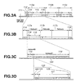
- FIGS. 3A to 3D A data structure of the CD-R is shown in FIGS. 3A to 3D.
- the data structure shown in FIGS. 3A to 3D is an example in which data is written in units of a packet to the CD-R by the so-called "Packet Writing" method.
- the data recording area of the CD-R includes a power calibration area (PCA) 111, program memory area (PMA) 112 and a plurality of sessions 113a, 113b and 113c in this order beginning from the near-center inner circumference of the optical disc.
- PCA power calibration area
- PMA program memory area
- the writing laser power is calibrated.
- This area further includes a test area in which a trial write is actually made, and a count area in which the used status of this test area is recorded.
- information such as a recording data mode, write start and write end positions, etc. are provisionally stored.
- Each of the plurality of sessions 113a, 113b and 113c includes a lead-in area 114, program area 115 and a lead-out area 116 in this order beginning from the inner circumference of the optical disc.
- the lead-in area 114 is used to read data written in the program area 115, and will have TOC (table of contents) information or the like written therein. At the time of data reading, the optical pickup can instantly access a desired recording track by reading the TOC information written in the lead-in area 114.
- the lead-out area 116 will have variety of information on the optical disc recorded therein.
- the lead-out area 116 of the session area 113c located along the outermost circumference of the optical disc serves as a buffer area to prevent the optical pickup of the optical disc drive from overrunning.
- the program area 115 will actually have user data written therein.
- one session includes three data tracks 117a, 117b and 117c.
- Each of the data tracks 117a, 117b and 117c to which a corresponding track number "TNO" is assigned includes two areas each having an "Index" as shown in FIG. 3C.
- An area 118 having an index of "00” will have TD (track descriptor) information which is track information written therein.
- an area 119 having an index of "01” will have user data in units of a packet 120. That is, user data is continuously written at each packet 120 in the area 119 having the index of "01".
- a fixed-length packet method in which one packet has a length fixed to 32 data blocks
- a variable-length packet method in which one packet is variable in length.
- the fixed-length packet method is adopted by way of example herein to write user data.
- the packet 120 includes a plurality of data blocks 121.
- the data block 121 is a mass of data being a unit of access used when the optical disc drive accesses user data in the optical disc, and normally includes 2352 bytes of user data. Note that the data block 121 is also called "data sector”.
- the packet 120 has appended thereto a plurality of data linking blocks necessary for linking between this packet 120 and an adjacent packet 120.
- Each of the data linking blocks 122 is provided as a guard area, according to a predetermined linking rule, to prevent user data from being missing at a linking position due to interleaving of the user data.
- the data linking block 122 includes a linking block 123 appended to the head of the packet 120, a plurality of run-in blocks 124 provided next to the linking block 123, and a plurality of run-out blocks 125 appended to the tail of the packet 120.
- a preceding packet 120 and a packet 120 after the preceding packet 120 will be linked to each other by the plurality of data linking blocks 122 including the run-out block 125 appended to the tail of the preceding packet 120, linking block 123 and the run-in block 124 appended to the head of the trailing packet 120.
- FIG. 4 shows an example of the data structure at a position where the packets 120 are linked to each other according to the linking rule adopted in the CD-R having the current format.
- two run-out blocks 125 are appended to the tail of the preceding packet 120 and one linking block 123 and four run-in blocks 124 are appended to the head of the trailing packet 120. Therefore, the packets 120 including 32 data blocks 121 for example are linked to each other by seven data linking blocks 122.
- the number of the data linking blocks 122 is set as small as possible in embodiments of the present invention.
- a total of the data linking blocks can be made three, namely, the data linking blocks may include one link block 123, one run-in block 124 and one run-out block 125. This will further be described later.
- data is coded with a Reed-Solomon code (C2 code) at each data unit of 24 bytes (12 words) and a 4-byte parity (Q parity) is appended to the coded data.
- C2 code Reed-Solomon code
- Q parity 4-byte parity
- User data and Q parity are interleaved, and then subjected to coding by a Reed-Solomon code (C1 code), and further a 4-byte parity (P parity) is appended to the coded data, thereby providing a total of 32 bytes of data.
- the 4-byte Q parity and 4-bytes P parity are appended to each user data of 24 bytes by the CIRC error-correction coding to provide the 32 bytes of data.
- a 2-byte frame sync signal "Frame Sync” and 1-byte subcode “Subcode” are appended to the 32 bytes of data to form one frame which is a data transmission unit, as shown in FIG. 5.
- Subcode includes eight channels P to W, and one bit for each channel (one byte in total) is inserted in each frame. Subcodes in a total of 98 frames will complete a piece of data. As shown in FIG. 6, a data block (data sector) being a unit of access in which th optical disc drive will access the subcode is composed of the 98 frames of which the subcodes complete one data unit.
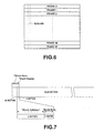
- User data included in one data block is of 2352 bytes (24 bytes by 98) in total, and it includes, at the head thereof, 12 bytes of block sync signal "Block Sync" and 4 bytes of "Block Header” as shown in FIG. 7.
- Block Header 3 bytes thereof is assigned as a "Block Address”, and the rest (1 byte) is assigned as a "Mode Byte” which indicates the attribute of the block.
- the subcodes included in one data block are a total of 98 bytes of data of which the first 2 bytes are assigned to a subcode sync signal "S 0 , S 1 " as shown in FIG. 8.
- the remaining 96 bytes are assigned to channels P to W.
- the channels P and Q are used for access to a data block to which the subcodes belong, and the channels R to W are used to record incidental data.
- Data will be subjected to the CIRC interleaving as in the above before being written to the CD-R.
- the CIRC interleaving is to impart a delay of 0, D, 2D, ..., 27D to a total of 28 bytes of data, respectively, to which 4 bytes of Q parity has been appended.
- data to be written in units of a packet have a data linking block 122 appended to each packet 120 thereof according to a predetermined linking rule as in the above.
- the linking rule applied to the CD-R having the current format will be described herebelow. According to that linking rule applied to the CD-R having the current format, data should be linked at a position of 26 EFM frames from the leading edge of a subcode sync signal "S 0 , S 1 " of a link block.
- the EFM frame is a unit of data transmission and the same as the frames forming together the aforementioned data block.
- the reason why the data linking position is not determined with reference to the leading edge of the block sync signal "Block Sync" but to the leading edge of the subcode sync signal "S 0 , S 1 " is that since the block sync signal "Block Sync" is also interleaved, it cannot be read after being interleaved.
- the data linking position is allowed to have a shift of ⁇ 4 EFM frames but the linking rule will be described on the assumption that there is not such a shift of the data linking position, for the simplicity of explanation.
- the "minimum delay encoder” means an encoder having not any circuit delay other than the intentional delay by the interleaving.
- two run-out blocks will be provided at the tail of a preceding data and one linking block and four run-in blocks be provided at the head of a trailing data, when the data area linked to each other.
- the user data will be linked by means of these seven data linking blocks.
- a block to be read should be judged to be a data linking block. That is, if the data linking block can correctly be read, it can be removed from the series of data to generate reading data properly.
- FIG. 9 data status before being subjected to the CIRC interleaving is shown in the upper portion of each of the drawings while data status after being interleaved with a delay parameter D of 4 (frames) is shown in the lower portion. Also, in the data after being so interleaved, shown in the lower portion in FIG. 9, data series to be subjected to error correction by the C2 code is shown obliquely in the direction of arrow A while data series to be subjected to error correction by the C1 code is shown vertically in the direction of arrow B.
- D delay parameter 4
- post-write restart since data included within a range of up to 108-th EFM frame from the linking position include one having been interleaved before and also after the write stop position, it will not be able to correctly be read, and so the first run-in block will not be able to correctly be read. However, the second and subsequent run-in blocks can correctly be read. Of course, the post-write restart user data can correctly be read since they are after the fourth run-in block.
- the linking rule is such that when linking data having been interleaved with the delay parameter D of 4 and maximum delay of 108 EFM frames, the user data can of course be read correctly, and at least one run-out block and one run-in block can correctly be read. Also, a number of run-in blocks, possibly larger than really required, are provided so that positive re-synchronization therewith is assured when reading the post-write restart data.
- each of the data linking blocks are a data block to which no user data is written, namely, a data block which is meaningless as user data
- the optical disc drive has to positively detect the position of the data linking block meaningless as user data, remove the data linking blocks from a series of data read from the CD-R and generate reading data.
- the block can be judged to be a run-out block, namely, it will be detected that the optical disc drive has reached the data linking block.
- the second run-out block will not correctly be read and no "Mode Byte” can be detected from the second run-out block.
- the optical disc drive can detect, by detecting the "Mode Byte" in the first run-out block, when it has reached the data linking block.
- the block can be judged to be a run-in block and it can be detected that there are no more data linking blocks.
- the first run-in block will not correctly be read and no "Mode Byte” can be detected from the first run-in block.
- the optical disc drive can detect, by detecting the "Mode Byte” in any of the second and subsequent run-in blocks, when there are no more data linking blocks.
- the optical disc drive can detect, at the time of data reading, when it has reached a data linking block and when there are no more data linking blocks, it will be able to positively detect the position of the data linking block, remove the data linking block from the series of data read from the CD-R, and generate reading data.
- the number of data linking blocks should desirably be as small as possible.
- the second run-out block should be provided, and the first run-out block is provided to make it possible to detect when the optical disc drive has reached the data linking blocks. Therefore, if it is possible to detect, without reading the first run-out block, when the optical disc drive has reached the data linking block, the first run-out block will be unnecessary and thus the number of data linking blocks can be reduced.
- the number of run-out blocks is reduced by appending a data linking block to each predetermined amount of user data to make it possible to predict the position of the data linking block. That is, if the amount of user data to which the data linking block is appended is set constant, the position of the data linking block can be predicted by reading data while monitoring the "Block Address" in the "Block Header" in the user data block. Therefore, the first run-out block in the example shown in FIG. 9 is unnecessary and thus only one run-out block may be used as the data linking block.
- a data linking block is appended at every 32 data blocks of user address. Therefore, by detecting the position of the thirty-second user data block in each packet while monitoring the "Block Address" in each user data block, it will be known that the thirty-second user data block is followed by a data linking block and thus it can positively be detected when the data linking block is reached.
- such identification information may be written in the CD-R as an ATIP wobble signal from a wobbling groove 105 formed in the lead-in area 114 of the session 113a located along the innermost disc circumference as shown in FIG. 3A for example. That is, the ATIP wobble signal from the wobbling groove 105 provided in the lead-in area 114 includes "Special Information" indicative of incidental information in addition to time-base information indicative of an absolution position on the optical disc. A frame assigned as the "Special Information" has a "reserved” part. The identification information for determining that user data has been written in units of the fixed-length packet may be included in the "reserved" part.
- identification information for determining that user data has been written in units of the fixed-length packet may be included in a Q channel of a subcode written to the PMA 112.
- the Q channel of the subcode written to the PMA 112 there is defined an item indicative of a disc ID. Since the item indicating the disc ID includes a "reserved" part, the identification information for determining that the user data has been written in units of the fixed-length packet can be included in the "reserved" part.
- identification information indicating that user data has been written in units of the fixed-length packet can be included in the Q channel of a subcode written to the lead-in area 114 of the session. That is, since an item indicating TOC information is defined in the Q channel of the subcode written to the lead-in area 114 and the item indicating the TOC information has a part indicating a recording format of the session, the identification information indicating that the user data has been written in units of the fixed-length packet can be included in that part.
- identification information indicating that user data has been written in units of the fixed-length packet can be included as TD (track descriptor) written to the area 118 of the data track, having an index "Index" "00".
- the run-out block requisite to detect the position of the data linking block is unnecessary and thus the number of data linking blocks can be reduced correspondingly.
- the data, interleaved as that before the write stop and deployed in the buffer memory and which actually be after the linking position due to the interleaving, will correspond to a former half of the data after restarting of the data writing. Since the data has been processed as pre-write stop data, it will not be handled as post-write stop data and thus the former half will be missing. Therefore, the latter half of the post-write restart data interleaved and deployed in the buffer memory has a part where on data exists (filled with "0" data in practice).
- the C1 series including the part having no data cannot correctly be subjected to error correction at the time of reading the data after the restart of data writing, and cannot correctly be read. More specifically, in the example shown in FIG. 9, since up to the first run-in block includes many parts having not data as the C1 series, the first run-in block will not be able to correctly be read.
- correct reading of the first run-in block makes it possible to reduce the number of run-in blocks.
- at least four run-in blocks are provided a for positive re-synchronization at the time of reading post-write restart data.
- the reliability of read data is maintained very high through a strong error correction and so, if a run-in block just before the user data can correctly be read, almost positive re-synchronization is possible.
- such an arrangement is made that by correctly reading the first run-in block, the second and subsequent run-in blocks in the example shown in FIG. 9 are made unnecessary and the number of run-in blocks is reduced to one.
- the part having no data should be filled with correct data when the post-write restart data is deployed in the buffer memory, and the full after the restart of data writing be written to the CD-R and linked.
- the "correct" data refers to a one interleaved as the pre-write stop data and deployed in the buffer memory but which is actually after the linking position due to the interleaving. Therefore, to fill a part having no data with correct data, for example, pre-write stop data deployed in the buffer memory, should be stored, have the stored pre-write stop data appended thereto when the post-write restart data is deployed in the buffer memory, to provide a series of data, and the series of data be written to the CD-R.
- the pre-write stop data deployed in the buffer memory should be left in the buffer memory also after the data writing is stopped, the post-write restart should be deployed in the buffer memory in which the pre-write stop data has already been deployed, the data across the linking position is prevented from being missing to provide a series of data, and only the data after the linking position is written to the CD-R and linked.
- run-in block provided can correctly be read. Namely, the number of run-in blocks can be limited to one.
- the above method cannot be applied in case the buffer memory has to be updated after the data writing is stopped and before it is restarted. For example, in case data is to be recorded to any other disc before the data writing is stopped and before it is restarted, the above method cannot be applied because the pre-write stop data cannot be left in the buffer memory.
- the pre-write stop data interleaved and deployed in the buffer memory but which will actually be after the linking position due to the interleaving may be re-generated when the post-write restart data is deployed in the buffer memory, and the re-generated data may be appended to the post-write restart data deployed in the buffer memory.
- the data linking blocks should include only the “Block Address” of the data linking blocks, "Mode Byte”, and “Recorder ID” indicating the type of a recorder in which the data linking blocks have been written as necessary. That is, meaningful ones of the data linking blocks are only the “Block Address”, “Mode Byte” and “Recorder ID”. If these can be re-generated, the data in the data linking blocks can be re-generated.
- the "Block Address” and “Mode Byte” can easily be re-generated after the data writing is restarted, even if they have been processed as pre-write stop data. That is, since the "Block Address” can be determined by counting down from the "Block Address” of the trailing data block and the type of data linking blocks which will miss data is always the same, namely; for example in the example shown in FIG. 9, the second run-out block will always miss data, it suffices to always generate a "Mode Byte” corresponding to the type of data linking block.
- the "Recorder ID” should be re-generated by reading once data in the data linking block before the data writing is stopped and whose data is not missing and re-generating the same data as the data thus read after the data writing is restarted. However, in case the number of run-out blocks is minimized as in the above, the "Recorder ID” cannot be read from data linking block before the data writing is stopped (will be referred to as "pre-write stop data lining block” hereunder), in some cases.
- the "Recorder ID” may not be included in the data in the data linking blocks (run-out block and linking block) processed as pre-write stop data. Since the "Recorder ID” is optionally written as necessary, it may be defined that the “Recorder ID” should be included only in the data in the data linking block (run-in block) processed as post-write restart data. In this case, it is only the "Block Address” and "Mode Byte” that have to be re-generated, and thus they can easily be re-generated.
- the data re-generated as in the above is interleaved along with the post-write restart data for example and deployed in the buffer memory.
- a full series of data across the linking position will be deployed in the buffer memory.
- pre-write stop user data is written in units of a fixed-length packet and identification information for determining that the user data has been written in units of the fixed-length packet is read to predict the position of data linking block, thereby reducing the number of run-out blocks to one for example. Also, by storing or re-generating data in the data linking block, which will be across the linking position due to the interleaving and which will be missing as post-write restart data, and appending the stored or re-generated data to data to be processed as post-write restart data, in order to prevent data from being missing, the number of run-in blocks is reduced to one for example.
- the number of data linking blocks can be reduced to a minimum of three: one link block, one run-in block and one run-out block.
- the number of data linking blocks being meaningless as user data can considerably be reduced and user data can be recorded more for the recording capacity corresponding to the reduction of the number of data linking blocks, whereby user data can efficiently be recorded.
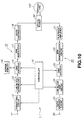
- FIG. 10 shows an example construction of the optical disc drive.
- the optical disc drive is generally indicated with a reference 1.
- This optical disc drive 1 is constructed to write and/or read data to and/or from a recordable optical disc (CD-R). It writes data to the CD-R while linking it in units of a fixed-length packet and reads data having been written to the CD-R in units of the fixed-length packet to the reading signal.
- CD-R recordable optical disc
- the optical disc drive 1 includes a data recording system generally indicated with a reference 10 and which records data supplied to a host computer or the like to a CD-R 100, and a data playback or reading system generally indicated with a reference 20 and which reads data recorded in the CD-R 100 and supplies the read data to the host computer or the like.
- the data recording system 10 has an input terminal 11 to which data (user data) from the host computer or the like is supplied.
- the user data supplied at the input terminal 11 is first supplied to a formatting circuit 12.
- the formatting circuit 12 blocks and packetizes user data supplied from the input terminal 11 according to a predetermined format.
- One data block include for example 2352 bytes of user data, and one packet includes for example 32 data blocks.
- the packet is a minimum unit of data to be continuously written to the CD-R and-data will not be written to the CD-R in any unit smaller than the packet.
- APacket Writing@ in which data is written in units of a packet, data can be written by a variable-length packet method in which the number of data blocks included in one packet is variable.
- the optical disc drive 1 according to the present embodiment is so designed that data is written by the fixed-length packet method in which data is written the number of data blocks included one packet is fixed.
- a formatting circuit 12 provided in the optical disc drive 1 packetizes user data supplied from an input terminal 11 thereof at every 32 data blocks for example. Also the formatting circuit 12 generates identification information for determining that user data is written in units of a fixed-length packet, and embeds the identification information in a series of data.
- the user data blocked and packetized by the formatting circuit 12 is supplied to a linking block appending unit 13.
- the linking block appending unit 13 appends a data linking block necessary for linking of data to each packet of the user data supplied from the formatting circuit 12. More specifically, the linking block appending unit 13 appends one linking block and one run-in block to the head of each packet for example while appending one run-out block to the tail of each packet. Then the data having thus appended to each packet thereof a total of three data linking blocks is supplied to a CIRC encoder 15 also provided in the optical disc drive 1.
- the CIRC encoder 15 includes a C2 encoder, interleaver and a C1 encoder.
- the CIRC encoder 15 makes CIRC (cross interleave Reed-Solomon Code) error correction coding of the data supplied from the linking block appending unit 13 under the control of the controller 14.
- the data supplied from the linking block appending circuit 13 is first supplied to the C2 encoder.
- This C2 encoder makes a Reed-Solomon coding (C2 code) of the supplied data at each data unit of 24 bytes (12 words) and appends 4 bytes of parity (Q parity) to the coded data.
- C2 code Reed-Solomon coding
- Q parity parity
- the interleaver has a delay parameter D of "4" (frames) set therein and will be selected for data write to the normal-density CD-R.
- D delay parameter
- the interleaver When the interleaver is supplied with the data having the Q parity appended thereto, it interleaves the data with a maximum delay of 108 frames (27 ⁇ 4 frames) for example.
- the data having thus been interleaved is supplied to the C 1 encoder.
- the C1 encoder makes a Reed-Solomon coding (C1 code) of the data having the Q parity appended thereto at each data unit of 28 bytes and further appends 4 bytes of parity (P parity) to the coded data.
- C1 code Reed-Solomon coding
- the data thus subjected to the CIRC error correction is deployed in a buffer memory 16 and then supplied to an EFM modulation circuit 17 where it will be subjected to EFM modulation (eight to fourteen modulation).
- EFM modulation (eight to fourteen modulation).
- the data thus EFM-modulated is supplied to a write controller 18.
- the write controller 18 generates a recording signal corresponding to data going to be written to the CD-R 100 under the control of the controller 14, and supplies the recording signal to an optical pickup 50.
- the optical pickup 50 Based on the recording signal supplied from the write controller 18, the optical pickup 50 forms, in the recording area of the CD-R 100, a pit (mark) row corresponding to data to be written.
- the user data and a variety of information including identification information supplied from the host-side computer or the like will be recorded to the CD-R.
- the controller 14 controls the operation of each component of the optical disc drive 1 so that data before the linking position at a stage before the interleaving is processed as the pre-write stop data. That is, the data before the linking position before the interleaving will be interleaved by the interleaver in the CIRC encoder 15 and deployed in a buffer memory 16 connected to the CIRC encoder 15. Only the one of the series of data deployed in the buffer memory 16, which actually lies before the linking position, is supplied to the EFM modulation circuit 17 where it is EFM modulated, and converted to a recording signal by the write controller 18 and supplied to the optical pickup 50. Thus, the data before the linking position in practice will be written to the data recording area of the CD-R 100.
- the controller 14 controls the operation of each component of the optical disc drive 1 so that the data after the linking position at a step before the interleaving is processed as the post-write restart data. At this time, in the former half of the post-write restart, there will be missing the data which will lie after the linking position due to the interleaving.
- the controller 14 controls the operation of each component of the optical disc drive I so that the part having no data can be filled with correct data.
- the controller 14 reserves the pre-write stop data deployed in the buffer memory 16 in the buffer memory 16 until the data writing is restarted.
- the post-write restart data is interleaved by the interleaver in the CIRC encoder 15 and deployed in the buffer memory 16, it has the reserved post-write stop data appended thereto, and deployed as a series of data in the buffer memory 16.
- the series of data deployed in the buffer memory 16 only the data after the linking position is supplied to the EFM modulation circuit 17 where it will be EFM-modulated.
- the EFM-modulated data is converted by the write controller 18 to a recording signal which will be supplied to the optical pickup 50.
- the data after the linking position will be written to the data recording area of the CD-R 100 without any missing data.
- the controller 14 may control the operation of each component of the optical disc drive 1 to re-generate the missing data, that is, data having been processed as the post-write stop data after the linking position, when the post-write restart data is deployed in the buffer memory 16, and to append the re-generated data to the post-write restart data deployed in the buffer memory 16.
- the data after the linking position is written to the data recording area of the CD-R for no data to be missing when linking data, a proper data linkage is possible even if the number of run-in blocks included in the data linking blocks is limited to one. Therefore, by recording data to the CD-R 100 with the optical disc drive 1 according to the present embodiment, it is possible to efficiently record user data.
- a signal recorded as a pit (mark) row in the CD-R 100 is read by the optical pickup 50 and supplied to a playback amplifier 21.
- the playback amplifier 21 produces a reading signal (RF signal), focus error signal, tracking error signal, etc.
- the reading signal produced by the playback amplifier 21 is converted to digital data by a binarization circuit, clock extraction circuit and the like (not shown), and supplied to an EFM demodulation circuit 22. Also, the focus error signal and tracking error signal produced by the playback amplifier 21 are supplied to a servo controller (not shown). The servo controller will provide focus and tracking servo control of the optical pickup 50 on the basis of these focus and tracking error signals.
- the digital data (reading data) supplied to the EFM demodulation circuit 22 is the digital data (reading data) supplied to the EFM demodulation circuit 22 .
- the CIRC decoder 23 is provided correspondingly to the CIRC encoder 15 in the data recording system 10. It includes a C1 decoder, de-interleaver, and a C2 decoder. Under the control of the controller 14, the CIRC decoder 23 makes a CIRC error correction of the reading data supplied from the EFM demodulation circuit 22.
- the reading data from the EFM demodulation circuit 22 is first supplied to the C1 decoder where it is subjected to error correction with C1 code. Mainly random errors being small errors will be corrected by the C 1 code error correction.
- the reading data having been error-corrected with the C 1 code by the C 1 decoder is supplied to the de-interleaver which will de-interleave the reading data.
- the de-interleaver has a delay parameter D set to A4@ (frames) for example.
- D delay parameter
- the de-interleaver When the de-interleaver is supplied with data having Q parity appended thereto, it de-interleaves the data with a maximum delay of 108 frames (27 H 4 frames) for example.
- the reading data thus de-interleaved by the de-interleaver is supplied to the C2 decoder.
- the C2 decoder makes error correction of the de-interleaved reading data with the C2 code. Main a burst error being a large error will be corrected by the error correction with the C2 code.
- the reading data having been subjected to the error correction with the C2 code in the C2 decoder will be supplied to a linking block skipping circuit 24.
- the linking block skipping circuit 24 removes the data linking blocks from the reading data having been error-corrected by the CIRC decoder 23. That is, supplied with the reading data from the CIRC decoder 23, the linking block skipping circuit 24 removes one linking block and one run-in block appended to the head of each packet and one run-out block appended to the tail of ac packet.
- the position of data linking block is detected by the controller 14 by reading identification information indicating that user data has been written in units of a fixed-length packet. That is, checking, based on the identification information, that the user data has been written in units of the fixed-length packet, the controller 14 recognizes that the data linking block has been appended to each user data of 32 data blocks for example, and monitors the ABlock Address@ of a preceding user data block, thereby detecting the position of the data linking block.
- the run-in block is written with no missing data in the CD-R 100 so that it can correctly be read. Therefore, the position of the run-in block can be detected by referring to the AMode Byte@ in the run-in block.
- the controller 14 can correctly detect the position of the data linking block including from the leading run-out block to the last run-in block of the data linking blocks, and allow the linking block skipping circuit 24 to remove the data linking blocks.
- the reading data having the data linking blocks therein removed by the data linking block skipping circuit 24 is supplied to a data extraction circuit 25.
- the user data extracted by the data extraction circuit 25 is delivered as an output terminal 26, and supplied to the host-side computer or the like.
- the identification information written in the CD-R 100 is read to check that user data has been written in units of a fixed-length packet, thereby detecting the position of the data linking block and correctly removing the data linking blocks as in the above. So, even if the number of run-out blocks in the data linking blocks is limited to one, data can properly be read.
- a high density CD-R having for example a recording density about double that of the CD-R having the current format has been developed for these years.
- the present invention can effectively be applied to data write to, and/or read from, to such a high density CD-R.
- the delay parameter D in the CIRC interleaving is set to 7 frames.
- the interleaving will have an influence on a wider range, and to prevent user data from being missing, two run-out blocks are necessary as the data linking blocks.
- the number of data linking blocks has not to be increased for detection of the position of data linking block, so a total of four data linking blocks including two run-out blocks and one linking block and one run-in block is only required for appending to the high recording density CD-R.
- the present invention is effectively applicable for writing data to a CD-RW which is a rewritable optical disc.
- the CD-RW is a recording medium in which data is recorded by phase-change recording and its recording format is almost the same as that of the CD-R. Therefore, an optical disc drive constructed similarly to the optical disc drive having been described in the foregoing can support the CD-RW which is a rewritable optical disc.
- the CD-RW is lower in reflectance than the CD-R, so it is necessary to additionally provide an AGC (automatic gain controller) which can amplify even a weak signal.
- AGC automatic gain controller
- an embodiment of the present invention can handle data with a reduced number of data linking blocks, so it permits to record user data efficiently and properly read the recorded user data.
Landscapes
- Engineering & Computer Science (AREA)
- Signal Processing (AREA)
- Signal Processing For Digital Recording And Reproducing (AREA)
- Optical Recording Or Reproduction (AREA)
- Management Or Editing Of Information On Record Carriers (AREA)
Abstract
Description
Claims (17)
- A data reproducing method for reading data having been written in a data recording area of a recording medium, the data being interleaved with a data linking block appended at each fixed length packet as a recording unit, and linked at a linking position in the data linking block, the method comprising steps of:reading the data from the data recording area of the recording medium and de-interleaving the data thus read;detecting the position of the data linking block by checking that the data is a one having been written in units of the fixed length packet; andgenerating a reading data by removing the data linking block.
- The method as set forth in claim 1, wherein it is checked based on data written in the recording medium that the data has been written in units of the fixed length packet.
- The method as set forth in claim 1, wherein the data linking blocks include at least one run-out block, one link block and at least one run-in block.
- A data player for reading data having been written in a data recording area of a recording medium, the data being interleaved with a data linking block appended at each fixed length packet as a recording unit, and linked at a linking position in the data linking block, the apparatus comprising:means for reading the data from the data recording area of the recording medium;means for de-interleaving the data read from the data recording area of the recording medium; andmeans removing the data linking block from the de-interleaved data to generate a reading data;the reading signal generating means detecting the position of the data linking block by checking that the data has been written in units of the fixed length packet.
- The apparatus as set forth in claim 4, wherein it is checked based on data written in the recording medium that the data has been written in units of the fixed length packet.
- The apparatus as set forth in claim 4, wherein the data linking blocks include at least one run-out block, one link block and at least one run-in block.
- The apparatus as set forth in claim 4, wherein the data linking blocks include one run-out block, one link block and one run-in block.
- A data recording method for writing data to a data recording area of a recording medium by appending data linking blocks at each unit of data to continuously be written to the data recording area, interleaving the data to which the data linking blocks have been appended and linking the interleaved data at a linking position in the data linking block, the method comprising steps of:storing one, after the linking position, of the data in the data linking block which will be placed across the linking position due to the interleaving; andlinking the interleaved data by appending the stored data to subsequent data.
- The method as set forth in claim 8, wherein the data linking blocks include at least one run-out block, one link block and at least one run-in block.
- A data recorder for writing data to a data recording area of a recording medium, the apparatus comprising:means for appending data linking blocks at each unit of data to continuously be written to the data recording area;means for interleaving the data to which the data linking blocks have been appended; andmeans for writing the data to the data recording area of the recording medium while linking the interleaved data at a linking position in the data linking block;the data writing means storing one, after the linking position, of the data in the data linking block which will be placed across the linking position due to the interleaving, and linking the interleaved data by appending the stored data to subsequent data.
- The apparatus as set forth in claim 10, wherein the data linking blocks include at least one run-out block, one link block and at least one run-in block.
- The apparatus as set forth in claim 10, wherein the data linking blocks include one run-out block, one link block and one run-in block.
- A data recording method for writing data to a data recording area of a recording medium by appending data linking blocks at each unit of data to continuously be written to the data recording area, interleaving the data to which the data linking blocks have been appended and linking the interleaved data at a linking position in the data linking block, the method comprising steps of:reproducing one, after the linking position, of the data in the data linking block which will be placed across the linking position due to the interleaving; andlinking the interleaved data by appending the reproduced data to subsequent data.
- The method as set forth in claim 13, wherein the data linking blocks include at least one run-out block, one link block and at least one run-in block.
- A data recorder for writing data to a data recording area of a recording medium, the apparatus comprising:means for appending data linking blocks at each unit of data to continuously be written to the data recording area;means for interleaving the data to which the data linking blocks have been appended; andmeans for writing the data to the data recording area of the recording medium while linking the interleaved data at a linking position in the data linking block;the data writing means reproducing one, after the linking position, of the data in the data linking block which will be placed across the linking position due to the interleaving, and linking the interleaved data by appending the reproduced data to subsequent data.
- The apparatus as set forth in claim 15, wherein the data linking blocks include at least one run-out block, one link block and at least one run-in block.
- The apparatus as set forth in claim 15, wherein the data linking blocks include one run-out block, one link block and one run-in block.
Applications Claiming Priority (2)
| Application Number | Priority Date | Filing Date | Title |
|---|---|---|---|
| JP2000118513A JP2001297536A (en) | 2000-04-14 | 2000-04-14 | Data reproduction method, data reproduction device, data recording method, and data recording device |
| JP2000118513 | 2000-04-14 |
Publications (2)
| Publication Number | Publication Date |
|---|---|
| EP1146513A2 true EP1146513A2 (en) | 2001-10-17 |
| EP1146513A3 EP1146513A3 (en) | 2006-01-18 |
Family
ID=18629635
Family Applications (1)
| Application Number | Title | Priority Date | Filing Date |
|---|---|---|---|
| EP01303470A Withdrawn EP1146513A3 (en) | 2000-04-14 | 2001-04-12 | Data recording and reproducing |
Country Status (7)
| Country | Link |
|---|---|
| US (1) | US6917574B2 (en) |
| EP (1) | EP1146513A3 (en) |
| JP (1) | JP2001297536A (en) |
| KR (1) | KR100697751B1 (en) |
| CN (1) | CN1215477C (en) |
| MY (1) | MY127319A (en) |
| TW (1) | TW561465B (en) |
Cited By (2)
| Publication number | Priority date | Publication date | Assignee | Title |
|---|---|---|---|---|
| EP1324335A2 (en) | 2001-12-17 | 2003-07-02 | Samsung Electronics Co., Ltd. | Method and apparatus for recording data on optical recording medium |
| SG135933A1 (en) * | 2002-12-13 | 2007-10-29 | Sony Corp | Reproduction-only recording medium, reproducing apparatus, reproducing method, and disk manufacturing method |
Families Citing this family (15)
| Publication number | Priority date | Publication date | Assignee | Title |
|---|---|---|---|---|
| KR100669617B1 (en) * | 2001-05-24 | 2007-01-15 | 엘지전자 주식회사 | Data recording method of optical record player |
| JP2003067929A (en) * | 2001-08-29 | 2003-03-07 | Yamaha Corp | Optical disk, optical disk recording device, method for controlling the optical disk recording device and program |
| JP3846249B2 (en) * | 2001-09-28 | 2006-11-15 | ヤマハ株式会社 | Optical disk recording device |
| US6774486B2 (en) * | 2001-10-10 | 2004-08-10 | Micron Technology, Inc. | Circuit boards containing vias and methods for producing same |
| JP4077820B2 (en) * | 2002-05-20 | 2008-04-23 | サムスン エレクトロニクス カンパニー リミテッド | Optical disc and optical disc recording method |
| CN1592929A (en) * | 2002-08-17 | 2005-03-09 | Lg电子株式会社 | High-density optical disc, method for recording address and/or servo information on the high-density optical disc, and method for reproducing data recorded on the high-density optical disc |
| KR20040016536A (en) * | 2002-08-17 | 2004-02-25 | 엘지전자 주식회사 | Method for recording address information of high density read only optical disc and high density read only optical disc therof |
| KR100475094B1 (en) | 2002-09-16 | 2005-03-10 | 삼성전자주식회사 | Apparatus and method for detecting position of pickup |
| KR100524931B1 (en) | 2002-09-25 | 2005-10-31 | 삼성전자주식회사 | Apparatus and method for deciding area of optical disc |
| JP4184210B2 (en) * | 2003-03-25 | 2008-11-19 | 株式会社リコー | Method of judging validity of recording medium, program and computer-readable recording medium |
| KR100860985B1 (en) * | 2003-05-23 | 2008-09-30 | 삼성전자주식회사 | Recording / Playback Method Using Padding Information |
| WO2005057576A1 (en) * | 2003-12-11 | 2005-06-23 | Matsushita Electric Industrial Co., Ltd. | Signal processing circuit |
| US20100118679A1 (en) * | 2007-02-19 | 2010-05-13 | Koninklijke Philips Electronics N.V. | Multi-layer optical discs |
| CN101576445B (en) * | 2009-06-03 | 2010-12-01 | 重庆大学 | An anthropomorphic memory-based structural health monitoring failure sensor data recovery method |
| CN108647357B (en) * | 2018-05-17 | 2023-01-31 | 创新先进技术有限公司 | Method and device for data query |
Family Cites Families (11)
| Publication number | Priority date | Publication date | Assignee | Title |
|---|---|---|---|---|
| FR2656753B1 (en) * | 1989-12-29 | 1992-03-20 | Europ Rech Electr Lab | METHOD FOR LINKING DATA WHEN RECORDING ENCODED DATA ON AN OPTICAL DISC OF THE RECORDABLE TYPE. |
| JP3158474B2 (en) * | 1991-03-28 | 2001-04-23 | ソニー株式会社 | Recording method, disk recording device and disk reproducing device |
| JP3318841B2 (en) * | 1992-08-20 | 2002-08-26 | ソニー株式会社 | Reproduction device and reproduction method |
| JP3440952B2 (en) * | 1993-02-24 | 2003-08-25 | ソニー株式会社 | Data recording method and data reproducing method |
| JP2747268B2 (en) * | 1995-01-30 | 1998-05-06 | 株式会社東芝 | Method and apparatus for reproducing data according to navigation data, and method and apparatus for recording data with navigation data on recording medium |
| JP3874211B2 (en) * | 1996-10-31 | 2007-01-31 | ソニー株式会社 | Information recording method and apparatus |
| JP3796858B2 (en) * | 1996-11-15 | 2006-07-12 | ヤマハ株式会社 | Optical disk reading device |
| JP3070494B2 (en) * | 1996-11-15 | 2000-07-31 | ヤマハ株式会社 | Optical disk recording device |
| JP3659555B2 (en) * | 1998-09-01 | 2005-06-15 | 船井電機株式会社 | Disk unit |
| JP2000099401A (en) * | 1998-09-22 | 2000-04-07 | Sony Corp | Recording medium, recording method and recording device |
| JP2000251405A (en) * | 1999-02-26 | 2000-09-14 | Sanyo Electric Co Ltd | Disk recording device |
-
2000
- 2000-04-14 JP JP2000118513A patent/JP2001297536A/en not_active Withdrawn
-
2001
- 2001-04-09 TW TW090108463A patent/TW561465B/en not_active IP Right Cessation
- 2001-04-10 MY MYPI20011719A patent/MY127319A/en unknown
- 2001-04-12 EP EP01303470A patent/EP1146513A3/en not_active Withdrawn
- 2001-04-12 US US09/833,858 patent/US6917574B2/en not_active Expired - Fee Related
- 2001-04-13 KR KR1020010019853A patent/KR100697751B1/en not_active Expired - Fee Related
- 2001-04-13 CN CNB01116378XA patent/CN1215477C/en not_active Expired - Fee Related
Cited By (5)
| Publication number | Priority date | Publication date | Assignee | Title |
|---|---|---|---|---|
| EP1324335A2 (en) | 2001-12-17 | 2003-07-02 | Samsung Electronics Co., Ltd. | Method and apparatus for recording data on optical recording medium |
| EP1324335A3 (en) * | 2001-12-17 | 2006-11-02 | Samsung Electronics Co., Ltd. | Method and apparatus for recording data on optical recording medium |
| SG135933A1 (en) * | 2002-12-13 | 2007-10-29 | Sony Corp | Reproduction-only recording medium, reproducing apparatus, reproducing method, and disk manufacturing method |
| US7408853B2 (en) | 2002-12-13 | 2008-08-05 | Sony Corporation | Reproduction-only recording medium, reproducing apparatus, reproducing method, and disk manufacturing method |
| US8320225B2 (en) | 2002-12-13 | 2012-11-27 | Sony Corporation | Reproduction-only recording medium, reproducing apparatus, reproducing method, and disk manufacturing method |
Also Published As
| Publication number | Publication date |
|---|---|
| CN1324075A (en) | 2001-11-28 |
| US20010050891A1 (en) | 2001-12-13 |
| JP2001297536A (en) | 2001-10-26 |
| KR20010098589A (en) | 2001-11-08 |
| TW561465B (en) | 2003-11-11 |
| CN1215477C (en) | 2005-08-17 |
| US6917574B2 (en) | 2005-07-12 |
| KR100697751B1 (en) | 2007-03-21 |
| EP1146513A3 (en) | 2006-01-18 |
| MY127319A (en) | 2006-11-30 |
Similar Documents
| Publication | Publication Date | Title |
|---|---|---|
| US6917574B2 (en) | Data recording and reproducing apparatus and method for linking data using a decreased number of data linking blocks | |
| US7719946B2 (en) | Device and method for recording information enabling reduced response time of a recording device | |
| CN1963926B (en) | Disk record medium and its manufacture method | |
| EP1395987B1 (en) | Device and method for recording information | |
| JP3269097B2 (en) | Optical disc, recording method therefor and recording device therefor | |
| EP1483760B1 (en) | Device, record carrier and method for recording information | |
| US7016279B2 (en) | Method for recording and/or reproducing data on/from recording/recorded medium, reproducing apparatus, recording medium, method for recogizing recording/recorded medium, and method for recording and/or reproducing data for apparatus using recording/recorded medium | |
| US6438084B2 (en) | Data recording apparatus and method, data playback apparatus and method, and optical disc | |
| US6661763B2 (en) | Optical disk recording apparatus and recording control method for recording data in a lead-in area and a program area | |
| US20040057363A1 (en) | Optical disk drive with increased recording efficiency | |
| US7830769B2 (en) | Recording apparatus and recording method | |
| US6819642B2 (en) | Data recording device, data reproducing device, and optical disc | |
| KR100821950B1 (en) | Method and apparatus for recording information in multiple units | |
| RU2274912C2 (en) | Method of recording and/or playing back for record carrier, playback device, record carrier, method of determining record carrier and method of recording and playing back for device using record carrier | |
| JP2001291330A (en) | Optical recording medium, information recording device, and information reproducing device | |
| JP4147544B2 (en) | Recording medium, recording method, recording apparatus, reproducing method, and reproducing apparatus | |
| JP2001291331A (en) | Optical recording medium and information recording method | |
| JP2001210009A (en) | Playback device, recording device and dubbing device | |
| JP2005078673A (en) | Playback apparatus and format determination method | |
| HK1070739B (en) | Device, record carrier and method for recording information |
Legal Events
| Date | Code | Title | Description |
|---|---|---|---|
| PUAI | Public reference made under article 153(3) epc to a published international application that has entered the european phase |
Free format text: ORIGINAL CODE: 0009012 |
|
| AK | Designated contracting states |
Kind code of ref document: A2 Designated state(s): AT BE CH CY DE DK ES FI FR GB GR IE IT LI LU MC NL PT SE TR |
|
| AX | Request for extension of the european patent |
Free format text: AL;LT;LV;MK;RO;SI |
|
| PUAL | Search report despatched |
Free format text: ORIGINAL CODE: 0009013 |
|
| AK | Designated contracting states |
Kind code of ref document: A3 Designated state(s): AT BE CH CY DE DK ES FI FR GB GR IE IT LI LU MC NL PT SE TR |
|
| AX | Request for extension of the european patent |
Extension state: AL LT LV MK RO SI |
|
| 17P | Request for examination filed |
Effective date: 20060630 |
|
| AKX | Designation fees paid |
Designated state(s): DE FR GB NL |
|
| 17Q | First examination report despatched |
Effective date: 20120309 |
|
| STAA | Information on the status of an ep patent application or granted ep patent |
Free format text: STATUS: THE APPLICATION IS DEEMED TO BE WITHDRAWN |
|
| 18D | Application deemed to be withdrawn |
Effective date: 20120720 |