EP1146508A2 - Information recording medium - Google Patents
Information recording medium Download PDFInfo
- Publication number
- EP1146508A2 EP1146508A2 EP01303202A EP01303202A EP1146508A2 EP 1146508 A2 EP1146508 A2 EP 1146508A2 EP 01303202 A EP01303202 A EP 01303202A EP 01303202 A EP01303202 A EP 01303202A EP 1146508 A2 EP1146508 A2 EP 1146508A2
- Authority
- EP
- European Patent Office
- Prior art keywords
- area
- recording
- read
- recording medium
- reproducing
- Prior art date
- Legal status (The legal status is an assumption and is not a legal conclusion. Google has not performed a legal analysis and makes no representation as to the accuracy of the status listed.)
- Granted
Links
Images



Classifications
-
- G—PHYSICS
- G11—INFORMATION STORAGE
- G11B—INFORMATION STORAGE BASED ON RELATIVE MOVEMENT BETWEEN RECORD CARRIER AND TRANSDUCER
- G11B7/00—Recording or reproducing by optical means, e.g. recording using a thermal beam of optical radiation by modifying optical properties or the physical structure, reproducing using an optical beam at lower power by sensing optical properties; Record carriers therefor
- G11B7/24—Record carriers characterised by shape, structure or physical properties, or by the selection of the material
- G11B7/2407—Tracks or pits; Shape, structure or physical properties thereof
- G11B7/24073—Tracks
- G11B7/24082—Meandering
-
- G—PHYSICS
- G11—INFORMATION STORAGE
- G11B—INFORMATION STORAGE BASED ON RELATIVE MOVEMENT BETWEEN RECORD CARRIER AND TRANSDUCER
- G11B23/00—Record carriers not specific to the method of recording or reproducing; Accessories, e.g. containers, specially adapted for co-operation with the recording or reproducing apparatus ; Intermediate mediums; Apparatus or processes specially adapted for their manufacture
- G11B23/38—Visual features other than those contained in record tracks or represented by sprocket holes the visual signals being auxiliary signals
- G11B23/40—Identifying or analogous means applied to or incorporated in the record carrier and not intended for visual display simultaneously with the playing-back of the record carrier, e.g. label, leader, photograph
-
- G—PHYSICS
- G11—INFORMATION STORAGE
- G11B—INFORMATION STORAGE BASED ON RELATIVE MOVEMENT BETWEEN RECORD CARRIER AND TRANSDUCER
- G11B7/00—Recording or reproducing by optical means, e.g. recording using a thermal beam of optical radiation by modifying optical properties or the physical structure, reproducing using an optical beam at lower power by sensing optical properties; Record carriers therefor
- G11B7/007—Arrangement of the information on the record carrier, e.g. form of tracks, actual track shape, e.g. wobbled, or cross-section, e.g. v-shaped; Sequential information structures, e.g. sectoring or header formats within a track
-
- G—PHYSICS
- G11—INFORMATION STORAGE
- G11B—INFORMATION STORAGE BASED ON RELATIVE MOVEMENT BETWEEN RECORD CARRIER AND TRANSDUCER
- G11B7/00—Recording or reproducing by optical means, e.g. recording using a thermal beam of optical radiation by modifying optical properties or the physical structure, reproducing using an optical beam at lower power by sensing optical properties; Record carriers therefor
- G11B7/007—Arrangement of the information on the record carrier, e.g. form of tracks, actual track shape, e.g. wobbled, or cross-section, e.g. v-shaped; Sequential information structures, e.g. sectoring or header formats within a track
- G11B7/0079—Zoned data area, e.g. having different data structures or formats for the user data within data layer, Zone Constant Linear Velocity [ZCLV], Zone Constant Angular Velocity [ZCAV], carriers with RAM and ROM areas
-
- G—PHYSICS
- G11—INFORMATION STORAGE
- G11B—INFORMATION STORAGE BASED ON RELATIVE MOVEMENT BETWEEN RECORD CARRIER AND TRANSDUCER
- G11B7/00—Recording or reproducing by optical means, e.g. recording using a thermal beam of optical radiation by modifying optical properties or the physical structure, reproducing using an optical beam at lower power by sensing optical properties; Record carriers therefor
- G11B7/08—Disposition or mounting of heads or light sources relatively to record carriers
- G11B7/09—Disposition or mounting of heads or light sources relatively to record carriers with provision for moving the light beam or focus plane for the purpose of maintaining alignment of the light beam relative to the record carrier during transducing operation, e.g. to compensate for surface irregularities of the latter or for track following
- G11B7/0901—Disposition or mounting of heads or light sources relatively to record carriers with provision for moving the light beam or focus plane for the purpose of maintaining alignment of the light beam relative to the record carrier during transducing operation, e.g. to compensate for surface irregularities of the latter or for track following for track following only
-
- G—PHYSICS
- G11—INFORMATION STORAGE
- G11B—INFORMATION STORAGE BASED ON RELATIVE MOVEMENT BETWEEN RECORD CARRIER AND TRANSDUCER
- G11B7/00—Recording or reproducing by optical means, e.g. recording using a thermal beam of optical radiation by modifying optical properties or the physical structure, reproducing using an optical beam at lower power by sensing optical properties; Record carriers therefor
- G11B7/08—Disposition or mounting of heads or light sources relatively to record carriers
- G11B7/09—Disposition or mounting of heads or light sources relatively to record carriers with provision for moving the light beam or focus plane for the purpose of maintaining alignment of the light beam relative to the record carrier during transducing operation, e.g. to compensate for surface irregularities of the latter or for track following
- G11B7/0938—Disposition or mounting of heads or light sources relatively to record carriers with provision for moving the light beam or focus plane for the purpose of maintaining alignment of the light beam relative to the record carrier during transducing operation, e.g. to compensate for surface irregularities of the latter or for track following servo format, e.g. guide tracks, pilot signals
-
- G—PHYSICS
- G11—INFORMATION STORAGE
- G11B—INFORMATION STORAGE BASED ON RELATIVE MOVEMENT BETWEEN RECORD CARRIER AND TRANSDUCER
- G11B7/00—Recording or reproducing by optical means, e.g. recording using a thermal beam of optical radiation by modifying optical properties or the physical structure, reproducing using an optical beam at lower power by sensing optical properties; Record carriers therefor
- G11B7/24—Record carriers characterised by shape, structure or physical properties, or by the selection of the material
- G11B7/2407—Tracks or pits; Shape, structure or physical properties thereof
- G11B7/24091—Combinations of pits and tracks with specific interrelation
-
- G—PHYSICS
- G11—INFORMATION STORAGE
- G11B—INFORMATION STORAGE BASED ON RELATIVE MOVEMENT BETWEEN RECORD CARRIER AND TRANSDUCER
- G11B20/00—Signal processing not specific to the method of recording or reproducing; Circuits therefor
- G11B20/00086—Circuits for prevention of unauthorised reproduction or copying, e.g. piracy
- G11B20/0021—Circuits for prevention of unauthorised reproduction or copying, e.g. piracy involving encryption or decryption of contents recorded on or reproduced from a record carrier
- G11B20/00217—Circuits for prevention of unauthorised reproduction or copying, e.g. piracy involving encryption or decryption of contents recorded on or reproduced from a record carrier the cryptographic key used for encryption and/or decryption of contents recorded on or reproduced from the record carrier being read from a specific source
- G11B20/00253—Circuits for prevention of unauthorised reproduction or copying, e.g. piracy involving encryption or decryption of contents recorded on or reproduced from a record carrier the cryptographic key used for encryption and/or decryption of contents recorded on or reproduced from the record carrier being read from a specific source wherein the key is stored on the record carrier
- G11B20/00297—Circuits for prevention of unauthorised reproduction or copying, e.g. piracy involving encryption or decryption of contents recorded on or reproduced from a record carrier the cryptographic key used for encryption and/or decryption of contents recorded on or reproduced from the record carrier being read from a specific source wherein the key is stored on the record carrier the key being stored in a management area, e.g. the video manager [VMG] of a DVD
- G11B20/00304—Circuits for prevention of unauthorised reproduction or copying, e.g. piracy involving encryption or decryption of contents recorded on or reproduced from a record carrier the cryptographic key used for encryption and/or decryption of contents recorded on or reproduced from the record carrier being read from a specific source wherein the key is stored on the record carrier the key being stored in a management area, e.g. the video manager [VMG] of a DVD the key being stored in the lead-in area [LIA]
-
- G—PHYSICS
- G11—INFORMATION STORAGE
- G11B—INFORMATION STORAGE BASED ON RELATIVE MOVEMENT BETWEEN RECORD CARRIER AND TRANSDUCER
- G11B20/00—Signal processing not specific to the method of recording or reproducing; Circuits therefor
- G11B20/00086—Circuits for prevention of unauthorised reproduction or copying, e.g. piracy
- G11B20/0021—Circuits for prevention of unauthorised reproduction or copying, e.g. piracy involving encryption or decryption of contents recorded on or reproduced from a record carrier
- G11B20/00217—Circuits for prevention of unauthorised reproduction or copying, e.g. piracy involving encryption or decryption of contents recorded on or reproduced from a record carrier the cryptographic key used for encryption and/or decryption of contents recorded on or reproduced from the record carrier being read from a specific source
- G11B20/00253—Circuits for prevention of unauthorised reproduction or copying, e.g. piracy involving encryption or decryption of contents recorded on or reproduced from a record carrier the cryptographic key used for encryption and/or decryption of contents recorded on or reproduced from the record carrier being read from a specific source wherein the key is stored on the record carrier
- G11B20/00405—Circuits for prevention of unauthorised reproduction or copying, e.g. piracy involving encryption or decryption of contents recorded on or reproduced from a record carrier the cryptographic key used for encryption and/or decryption of contents recorded on or reproduced from the record carrier being read from a specific source wherein the key is stored on the record carrier the key being stored by varying characteristics of the recording track, e.g. by altering the track pitch or by modulating the wobble track
-
- G—PHYSICS
- G11—INFORMATION STORAGE
- G11B—INFORMATION STORAGE BASED ON RELATIVE MOVEMENT BETWEEN RECORD CARRIER AND TRANSDUCER
- G11B20/00—Signal processing not specific to the method of recording or reproducing; Circuits therefor
- G11B20/00086—Circuits for prevention of unauthorised reproduction or copying, e.g. piracy
- G11B20/00572—Circuits for prevention of unauthorised reproduction or copying, e.g. piracy involving measures which change the format of the recording medium
- G11B20/00586—Circuits for prevention of unauthorised reproduction or copying, e.g. piracy involving measures which change the format of the recording medium said format change concerning the physical format of the recording medium
- G11B20/00601—Circuits for prevention of unauthorised reproduction or copying, e.g. piracy involving measures which change the format of the recording medium said format change concerning the physical format of the recording medium wherein properties of tracks are altered, e.g., by changing the wobble pattern or the track pitch, or by adding interruptions or eccentricity
-
- G—PHYSICS
- G11—INFORMATION STORAGE
- G11B—INFORMATION STORAGE BASED ON RELATIVE MOVEMENT BETWEEN RECORD CARRIER AND TRANSDUCER
- G11B7/00—Recording or reproducing by optical means, e.g. recording using a thermal beam of optical radiation by modifying optical properties or the physical structure, reproducing using an optical beam at lower power by sensing optical properties; Record carriers therefor
- G11B7/24—Record carriers characterised by shape, structure or physical properties, or by the selection of the material
- G11B7/241—Record carriers characterised by shape, structure or physical properties, or by the selection of the material characterised by the selection of the material
- G11B7/242—Record carriers characterised by shape, structure or physical properties, or by the selection of the material characterised by the selection of the material of recording layers
- G11B7/243—Record carriers characterised by shape, structure or physical properties, or by the selection of the material characterised by the selection of the material of recording layers comprising inorganic materials only, e.g. ablative layers
- G11B2007/24302—Metals or metalloids
- G11B2007/24308—Metals or metalloids transition metal elements of group 11 (Cu, Ag, Au)
-
- G—PHYSICS
- G11—INFORMATION STORAGE
- G11B—INFORMATION STORAGE BASED ON RELATIVE MOVEMENT BETWEEN RECORD CARRIER AND TRANSDUCER
- G11B7/00—Recording or reproducing by optical means, e.g. recording using a thermal beam of optical radiation by modifying optical properties or the physical structure, reproducing using an optical beam at lower power by sensing optical properties; Record carriers therefor
- G11B7/24—Record carriers characterised by shape, structure or physical properties, or by the selection of the material
- G11B7/241—Record carriers characterised by shape, structure or physical properties, or by the selection of the material characterised by the selection of the material
- G11B7/242—Record carriers characterised by shape, structure or physical properties, or by the selection of the material characterised by the selection of the material of recording layers
- G11B7/243—Record carriers characterised by shape, structure or physical properties, or by the selection of the material characterised by the selection of the material of recording layers comprising inorganic materials only, e.g. ablative layers
- G11B2007/24302—Metals or metalloids
- G11B2007/2431—Metals or metalloids group 13 elements (B, Al, Ga, In)
-
- G—PHYSICS
- G11—INFORMATION STORAGE
- G11B—INFORMATION STORAGE BASED ON RELATIVE MOVEMENT BETWEEN RECORD CARRIER AND TRANSDUCER
- G11B7/00—Recording or reproducing by optical means, e.g. recording using a thermal beam of optical radiation by modifying optical properties or the physical structure, reproducing using an optical beam at lower power by sensing optical properties; Record carriers therefor
- G11B7/24—Record carriers characterised by shape, structure or physical properties, or by the selection of the material
- G11B7/241—Record carriers characterised by shape, structure or physical properties, or by the selection of the material characterised by the selection of the material
- G11B7/242—Record carriers characterised by shape, structure or physical properties, or by the selection of the material characterised by the selection of the material of recording layers
- G11B7/243—Record carriers characterised by shape, structure or physical properties, or by the selection of the material characterised by the selection of the material of recording layers comprising inorganic materials only, e.g. ablative layers
- G11B2007/24302—Metals or metalloids
- G11B2007/24314—Metals or metalloids group 15 elements (e.g. Sb, Bi)
-
- G—PHYSICS
- G11—INFORMATION STORAGE
- G11B—INFORMATION STORAGE BASED ON RELATIVE MOVEMENT BETWEEN RECORD CARRIER AND TRANSDUCER
- G11B7/00—Recording or reproducing by optical means, e.g. recording using a thermal beam of optical radiation by modifying optical properties or the physical structure, reproducing using an optical beam at lower power by sensing optical properties; Record carriers therefor
- G11B7/24—Record carriers characterised by shape, structure or physical properties, or by the selection of the material
- G11B7/241—Record carriers characterised by shape, structure or physical properties, or by the selection of the material characterised by the selection of the material
- G11B7/242—Record carriers characterised by shape, structure or physical properties, or by the selection of the material characterised by the selection of the material of recording layers
- G11B7/243—Record carriers characterised by shape, structure or physical properties, or by the selection of the material characterised by the selection of the material of recording layers comprising inorganic materials only, e.g. ablative layers
- G11B2007/24302—Metals or metalloids
- G11B2007/24316—Metals or metalloids group 16 elements (i.e. chalcogenides, Se, Te)
-
- G—PHYSICS
- G11—INFORMATION STORAGE
- G11B—INFORMATION STORAGE BASED ON RELATIVE MOVEMENT BETWEEN RECORD CARRIER AND TRANSDUCER
- G11B2220/00—Record carriers by type
- G11B2220/20—Disc-shaped record carriers
- G11B2220/21—Disc-shaped record carriers characterised in that the disc is of read-only, rewritable, or recordable type
- G11B2220/211—Discs having both read-only and rewritable or recordable areas containing application data; Partial ROM media
-
- G—PHYSICS
- G11—INFORMATION STORAGE
- G11B—INFORMATION STORAGE BASED ON RELATIVE MOVEMENT BETWEEN RECORD CARRIER AND TRANSDUCER
- G11B7/00—Recording or reproducing by optical means, e.g. recording using a thermal beam of optical radiation by modifying optical properties or the physical structure, reproducing using an optical beam at lower power by sensing optical properties; Record carriers therefor
- G11B7/002—Recording, reproducing or erasing systems characterised by the shape or form of the carrier
- G11B7/0033—Recording, reproducing or erasing systems characterised by the shape or form of the carrier with cards or other card-like flat carriers, e.g. flat sheets of optical film
-
- G—PHYSICS
- G11—INFORMATION STORAGE
- G11B—INFORMATION STORAGE BASED ON RELATIVE MOVEMENT BETWEEN RECORD CARRIER AND TRANSDUCER
- G11B7/00—Recording or reproducing by optical means, e.g. recording using a thermal beam of optical radiation by modifying optical properties or the physical structure, reproducing using an optical beam at lower power by sensing optical properties; Record carriers therefor
- G11B7/004—Recording, reproducing or erasing methods; Read, write or erase circuits therefor
- G11B7/0045—Recording
- G11B7/00455—Recording involving reflectivity, absorption or colour changes
-
- G—PHYSICS
- G11—INFORMATION STORAGE
- G11B—INFORMATION STORAGE BASED ON RELATIVE MOVEMENT BETWEEN RECORD CARRIER AND TRANSDUCER
- G11B7/00—Recording or reproducing by optical means, e.g. recording using a thermal beam of optical radiation by modifying optical properties or the physical structure, reproducing using an optical beam at lower power by sensing optical properties; Record carriers therefor
- G11B7/24—Record carriers characterised by shape, structure or physical properties, or by the selection of the material
- G11B7/24003—Shapes of record carriers other than disc shape
- G11B7/24012—Optical cards
-
- G—PHYSICS
- G11—INFORMATION STORAGE
- G11B—INFORMATION STORAGE BASED ON RELATIVE MOVEMENT BETWEEN RECORD CARRIER AND TRANSDUCER
- G11B7/00—Recording or reproducing by optical means, e.g. recording using a thermal beam of optical radiation by modifying optical properties or the physical structure, reproducing using an optical beam at lower power by sensing optical properties; Record carriers therefor
- G11B7/24—Record carriers characterised by shape, structure or physical properties, or by the selection of the material
- G11B7/241—Record carriers characterised by shape, structure or physical properties, or by the selection of the material characterised by the selection of the material
- G11B7/252—Record carriers characterised by shape, structure or physical properties, or by the selection of the material characterised by the selection of the material of layers other than recording layers
- G11B7/258—Record carriers characterised by shape, structure or physical properties, or by the selection of the material characterised by the selection of the material of layers other than recording layers of reflective layers
- G11B7/2585—Record carriers characterised by shape, structure or physical properties, or by the selection of the material characterised by the selection of the material of layers other than recording layers of reflective layers based on aluminium
-
- Y—GENERAL TAGGING OF NEW TECHNOLOGICAL DEVELOPMENTS; GENERAL TAGGING OF CROSS-SECTIONAL TECHNOLOGIES SPANNING OVER SEVERAL SECTIONS OF THE IPC; TECHNICAL SUBJECTS COVERED BY FORMER USPC CROSS-REFERENCE ART COLLECTIONS [XRACs] AND DIGESTS
- Y10—TECHNICAL SUBJECTS COVERED BY FORMER USPC
- Y10T—TECHNICAL SUBJECTS COVERED BY FORMER US CLASSIFICATION
- Y10T428/00—Stock material or miscellaneous articles
- Y10T428/21—Circular sheet or circular blank
Definitions
- the present invention relates to an information recording medium utilized for an optical recording/reproducing apparatus, which reads out information recorded on the information recording medium by making the information recording medium relatively move, particularly, relates to an information recording medium comprising a read only area of enabling to read out information and a recording/reproducing area of enabling to record and reproduce information.
- Such information recording mediums are divided into two types in consideration of mechanism of recording or reproducing: one is a read only type and the other is a recording/reproducing type, that is, a recordable type and an overwritable type.
- a read only type information recording medium is shipped out into a market with being prerecorded with information such as a CD audio disk typically, and is reproduced by a user.
- a recordable or overwritable type information recording medium is shipped out into a market without any recorded information, and a user records information on it and reproduces it if necessary.
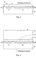
- FIG. 2 is a cross sectional view of such the information recording medium 301.
- the information recording medium 301 comprises a substrate 10, a recording layer 13, and a resin layer 14.
- a microscopic pattern is formed on a surface of the substrate 10 at a boundary area between the substrate 10 and the recording layer 13.
- Microscopic patterns constituting a read only area and a recording/reproducing area are engraved in areas corresponding to the read only and recording/reproducing areas respectively.
- microscopic patterns 11 corresponding to the read only area and other microscopic patterns 12 corresponding to the recording/reproducing area are engraved.
- a depth “d1" of the microscopic patterns 11 is ⁇ /4n
- a depth “d2" of the microscopic patterns 12 is ⁇ /8n, wherein ⁇ is a reproduction wavelength of a laser beam and "n" is a refractive index of the substrate 10 at the reproduction wavelength ⁇ .
- Specifying the depth of the microscopic patterns 11 to ⁇ /4n is caused by a phase depth in which a signal output from the read only area becomes maximum. Further, specifying the depth of the microscopic patterns 12 to ⁇ /8n is caused by that a push-pull signal related to tracking of the information recording medium becomes a maximum output.
- a defect has occurred when an information recording medium formed with microscopic patterns shown in Fig. 2 has been loaded in various recording/reproducing apparatuses, which are currently available in a market, and operated.
- a mode of the defect is out of tracking while reproducing the information recording medium with continuously traversing from a recording/reproducing area to a read only area. Further, an operation traversing reversely from the read only area to the recording/reproducing area is also defective.
- a recording/reproducing apparatus employs a push-pull method for tracking so as to record information in a groove and the push-pull method does not match with the information recording medium 301.
- the push-pull signal output is zero, a track can not be detected. Therefore, the reproduction stops at the track.
- output difference between a push-pull signal output of the read only area and a push-pull signal output of the recording/reproducing area is large, so that a servo system of the recording/reproducing apparatus can not follow properly. Accordingly, it is required to solve such the problem as out of tracking when an information recording medium having two areas is actually recorded and reproduced.
- an object of the present invention is to provide an information recording medium, which can solve the problem mentioned above.
- the present invention provides, according to an aspect thereof, an information recording medium, which comprises a substrate, a recording layer, and a resin layer, wherein the substrate is formed with a pit corresponding to a read only area and a groove corresponding to a recording/reproducing area without overlapping with each other, and wherein a reflectivity of the recording layer is more than 10 %, the information recording medium is characterized in that a push-pull signal output T1 reproduced from the read only area and another push-pull signal output T2 reproduced from the recording/reproducing area is more than 0.1 respectively and further 1.5 ⁇ T1/T2 ⁇ 0.5.
- Fig. 1 is a plan view of an information recording medium in a disk shape according to an embodiment of the present invention.
- Fig. 2 is a cross sectional view of an information recording medium common to a prior art and the present invention.
- Fig. 3 is a cross sectional view of an information recording medium according to the present invention.
- Fig. 4 is a cross sectional view of an information recording medium according to a first embodiment of the present invention.
- Fig. 5 is a plan view of a boundary area between a read only area and a recording/reproducing area of an information recording medium according to the present invention.
- Fig. 6 is a plan view of a boundary area between a read only area and a recording/reproducing area of an information recording medium according to the present invention.
- Fig. 7 is a plan view of a boundary area between a read only area and a recording/reproducing area of an information recording medium according to the present invention.
- Fig. 8 is a plan view of a boundary area between a read only area and a recording/reproducing area of an information recording medium according to the present invention.
- Fig. 9 is a cross sectional view of a 4-division photodetector utilized for recording and reproducing an information recording medium according to the present invention.
- Fig. 10 is a graph showing a relation between a depth of a read only area of an information recording medium and a push-pull signal output according to the present invention.
- Fig. 11 is a graph showing a relation between a depth of a recording/reproducing area of an information recording medium and a push-pull signal output according to the present invention.
- Fig. 12 is a plan view of an information recording medium in a card shape according to the present invention.
- Fig. 13 is a plan view of another information recording medium in a card shape according to the present invention.
- Fig. 1 is a plan view of an information recording medium in a disk shape according to an embodiment of the present invention.
- Fig. 2 is a cross sectional view of the information recording medium shown in Fig. 1.
- Fig. 3 is another cross sectional view of the information recording medium shown in Fig. 1.
- an information recording medium 1 in a disk shape comprises a read only area 31 and a recording/reproducing area 32.
- the read only area 31 and the recording/reproducing area 32 is allocated in an innermost circumference area and an outer circumference area of the information recording medium 1 respectively. However, these allocations can be reversely arranged. Further, these two areas are formed not so as to overlap with each other. Some gap existing between two areas can be allowable. Furthermore, a plurality of the read only and recording/reproducing areas 31 and 32 can also be allowable.
- Fig. 2 shows a fundamental configuration of an information recording medium 1 of the present invention.
- the information recording medium 1 of the present invention is resemble to that of the prior art in appearance, so that the same drawing is used for explaining the present invention.
- Fig. 3 also shows a fundamental configuration of an information recording medium 2 of the present invention.
- the configuration shown in Fig. 3 is a same as that shown in Fig. 2 except a reading out direction, that is, an optical path. An optical path will be explained.
- the information recording medium 1 or 2 comprises a substrate 10, a recording layer 13 and a resin layer 14.
- a microscopic pattern is formed on a surface of the substrate 10 at a boundary between the substrate 10 and the recording layer 13.
- Microscopic patterns 11 and 12 are formed in areas corresponding to the read only area 31 and the recording/reproducing area 32 respectively without overlapping with each other.
- these microscopic patterns 11 and 12 have a depth of "d1" and "d2" respectively. Either cases can be acceptable whether or not the depth "d1" of the microscopic patterns 11 is a same as the depth "d2" of the microscopic patterns 12. However, a depth must be designated so as to be able to obtain a range of push-pull signal output, which will be depicted.
- Layers composed of the substrate 10, the recording layer 13, and the resin layer 14 are formed in parallel to each other.
- the resin layer 14 is adhered on the recording layer 13 with continuously covering over all areas including at least the read only area 31 and the recording/reproducing area 32.
- recording or reproducing by light beam is performed on the recording layer 13, it is arbitrarily determined that a laser beam having a wavelength of ⁇ nm, which is stopped down by a objective lens having a numerical aperture of NA, is irradiated from either side of the information recording medium 1. In other words, it is arbitrarily determined whether the laser beam is irradiated from the substrate 10 side or the resin layer 14 side.
- a path of irradiating the laser beam that is, an optical path has a certain refractive index "n" for the wavelength ⁇ .
- An effective optical length is determined by the refractive index "n".
- the substrate 10 is illustrated as an optical path in Fig. 2.
- the resin layer 14 can be used as an optical path as shown in Fig. 3.
- the refractive index "n" of these optical paths is desirable to be 1.4 through 1.7 in consideration of interchangeability with current optical disks, more desirable to be 1.45 through 1.65. Further, if birefringence of the optical path is designated to be less than 100 nm by double paths, deviation of reproduction output can be sufficiently suppressed, so that it is most desirable.
- Synthetic resins of high strength and various ceramics can be utilized for a material of the substrate 10.
- Actual materials are such resins as polycarbonate, polymethyle methacrylate, polystyrene, polycarbonate-polystyrene copolymer, polyvinyl chloride, alicyclic polyorefin, polymethyle pentene, polyacetate resin, and various copolymer having a resin frame of them, and such synthetic resin as block polymer, and such ceramics as soda aluminosilicate glass, boron silicate glass, and silica glass.
- the recording layer 13 is at least made of a recording material of which a reflectivity is more than 10 % at the wavelength ⁇ .
- a recording material of enabling recordable or write once recording such dye materials as cyanine dye, phthalocyanine dye, naphthalocyanine dye, azo dye, and naphthoquinone dye.
- a phase change recording material, so called, and a magneto-optical recording material can be used for a recording material of enabling overwrite.
- phase change recording materials are as follows: alloys made of some materials selected from indium, antimony, tellurium, selenium, germanium, gallium, bismuth, platinum, gold, silver, copper, tin, sulfur, and aluminum, wherein an alloy includes compound such as oxide, nitride, and carbide. Moreover, in a case of magneto-optical recording material, there existed an alloy, which contains at least a transition metal and a rare earth element.
- the alloy is made of some materials selected from terbium, cobalt, iron, gadolinium, neodymium, dysprosium, bismuth, palladium, samarium, holmium, praseodymium, manganese, titanium, erbium, ytterbium, lutetium, chromium, tin, platinum, wherein an alloy includes compound such as oxide, nitride, and carbide.
- the recording layer 13 can be multi-layered or laminated by an optical interference film such as SiN, SiC, SiO, ZnS, ZnSSiO, AlO, GeN, MgF, InO, and ZrO, and an optical reflection film such as aluminum, gold, silver, and titanium for a purpose of improving performance.
- an optical interference film such as SiN, SiC, SiO, ZnS, ZnSSiO, AlO, GeN, MgF, InO, and ZrO
- an optical reflection film such as aluminum, gold, silver, and titanium for a purpose of improving performance.
- the recording layer 13 can be laminated by a super resolution masking film or a contrast enhancing film, which is commonly known.
- the resin layer 14 is provided for protecting the recording layer 13 chemically and physically, and can be selected from thermosetting resins, ultra violet ray curable resins, various radiation including visible light curable resins, electron beam curable resins, moisture curable resins, and multiple liquid mixture curable resins. A surface of the resin layer 14 can be printed if necessary.
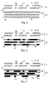
- Fig. 5 is a plan view of a boundary area between a read only area and a recording/reproducing area of an information recording medium partially enlarged according to the present invention.
- a gap having a distance of "G” hereinafter referred to a gap "G"
- the gap "G” exists between the microscopic patterns 11 of the read only area 31 and the microscopic patterns 12 of the recording/reproducing area 32.
- a recording/reproducing apparatus can jump across the gap "G” by forcing to drive a pickup or a like. According to our experiment, the jumping motion can be smoothly performed by setting the gap "G" in less than 25 ⁇ m.
- the microscopic patterns 11 of the read only area 31 is a group of pit 21, which is engraved by what is called a recording method of cutting.
- a track is composed of continuing groups of the pit 21.
- the microscopic patterns 12 utilized for the recording/reproducing area 32 are not formed in the read only area 31.
- a gap between each track is in a distance of P1 (hereinafter referred to a track pitch P1).
- the pit 21 is modulated by a well-known modulation method and formed a pit in various length.
- a minimal pit length closely relating to quality of a reproduction signal is defined as L1.
- the groups of pit 21 can be meandered or wobbled by applying a sinusoidal deflection to the pit 21 when the pit 21 is recorded with cutting.
- wobbling is recorded by either the CLV (constant linear velocity) or the CAV (constant angular velocity) method.
- a specific code which can not be rewritten by a user, is recorded in the read only area 31.
- the specific code is such a key or code as a key for ciphering, a key for deciphering, a code for permitting to record, a code for refusing to record, and a disk serial number inherent to each disk.
- a lead-in signal can be recorded as a same manner as that of a current read only disk.
- the microscopic patterns 12 in the recording/reproducing area 32 are composed of a group of groove 22.
- a gap between each groove 22 is called a land 23 commonly.
- Each groove 22 is spaced in a distance of P2 (hereinafter referred to a track pitch P2).
- the groove 22 can also be wobbled by applying a sinusoidal deflection to the groove 22 when the groove 22 is recorded with cutting. It is acceptable that wobbling is recorded by either the CLV or the CAV method.
- an address pit which specifies an address number, can be allocated in between each groove 22, that is, in the land 23.
- Fig. 6 is a plan view of the interface area as same as that of shown in Fig. 5 with showing a mark 24 written in the groove 22.
- Fig. 7 is a plan view of the interface area as same as that of shown in Fig. 5 with showing the mark 24 written in the land 23.
- the mark 24 is formed in the groove 22 by focusing a laser beam for recording on the groove 22.
- the mark 24 is modulated by a well-known modulating method, and then formed in various lengths.
- a minimal pit length closely relating to quality of a reproduction signal is defined as L2.
- the mark 24 can be written in between each groove 22, that is, in the land 23. Further, the mark 24 can be written in both the groove 22 and the land 23 although not shown in any drawings.
- the well-known modulation method applied for the read only and recording/reproducing areas 31 and 32 is a signal of which minimal mark length is specified to one of lengths such as 2T, 3T, 4T, and 5T.
- a signal system in which a minimal pit length or a minimal mark length is specified to 2T for example, such a signal system as an eight to twelve (8/12) modulation, which is composed of signals from 2T to 8T, can be utilized.
- signal systems such as an eight to fourteen (8/14) modulation, an eight to fifteen (8/15) modulation, and an eight to seventeen (8/17) modulation, which are composed of signals from 3T to 11T, and another signal system such as an eight to sixteen (8/16) modulation, which is composed of signal from 3T to 11T and 14T, can be utilized.
- each signal in the respective areas can be modulated by different modification methods.
- the depth d1 and d2 of respective areas of the information recording medium 1 according to the present invention are adjusted so as to enable to obtain a predetermined push-pull signal.
- a predetermined push-pull signal satisfies following inequalities simultaneously with defining that a push-pull signal output of the read only area 31 is T1 and a push-pull signal output of the recording/reproducing area 32 before recording is T2.
- respective push-pull signal outputs are desirable to be within a range of satisfying following inequalities simultaneously: T1 ⁇ 0.15 T2 ⁇ 0.15 and 1.4 ⁇ T1/T2 ⁇ 0.6.
- a range of tracking signal of the information recording medium according to the present invention is obtained by a limiting value, which is obtained by reproducing the information recording medium actually loaded in a player by means of the push-pull method.
- a result of experiment is shown in Table 1. By examining tracking ability in the read only area 31 with respect to T1, tracking is completely disabled by T1 in less than 0.08.
- Table 2 shows a result of examining tracking ability in the recording/reproducing area 31 with respect to T2. Tracking is completely disabled by T2 in less than 0.08 as same situation as that of T1. T2 Tracking 0.08 Disable 0.10 Enable 0.15 Enable 0.22 Enable 0.31 Enable 0.45 Enable
- T1 and T2 must be more than 0.1. Furthermore, the value is desirable to be more than 0.15, in consideration of a case that the information recording medium 1 is dusted or scratched.
- a limitation of continuous reproducibility over two areas is caused by that there is existed a limit in a dynamic range of a servo circuit of a recording apparatus. In other words, it is required that a difference between T1 and T2 is smaller. Therefore, with respect to the information recording medium 1, which satisfies the inequalities of T1 ⁇ 0.1 and T2 ⁇ 0.1, a limiting value is obtained by performing a traverse reproduction over two areas for various disk samples of T1/T2.
- Table 3 As shown in Table 3, the traverse reproduction over two areas is enabled in a case that T1/T2 is within a range from 0.5 to 1.5.
- the value is desirable to be within a range from 0.6 to 1.4, in consideration of a case that the information recording medium 1 is dusted or scratched.
- T1 T2 T1/T2 Traverse reproduction over areas 0.10 0.10 1.0 Enable 0.10 0.20 0.5 Enable 0.10 0.25 0.4 Disable 0.15 0.22 0.7 Enable 0.20 0.12 1.7 Disable 0.20 0.13 1.5 Enable 0.20 0.28 0.7 Enable 0.20 0.40 0.5 Enable 0.20 0.45 0.4 Disable 0.22 0.16 1.4 Enable 0.25 0.16 1.6 Disable 0.25 0.17 1.5 Enable 0.25 0.25 1.0 Enable 0.25 0.34 0.7 Enable 0.25 0.44 0.6 Enable
- a push-pull signal output is defined as follows: a push-pull signal is a signal, which is produced by calculating respective outputs from a 4-division photodetector utilized for a recording/reproducing apparatus as a pickup.
- Fig. 9 is a cross sectional view of a 4-division photodetector 9 utilized for recording and reproducing the information recording medium 1 according to the present invention.
- a horizontal and vertical axes are a radial direction and a tangential direction (track direction) respectively in corresponding to Figs. 5 through 7.
- Reproduced outputs of the 4-division photodetector 9 are Ia, Ib, Ic, and Id respectively.
- is measured by an AC (alternative current) coupling, and then total outputs, that is,
- the present invention specifies a push-pull signal output to a predetermined range.
- Fig. 1 is a plan view of an information recording medium in a disk shape according to an embodiment of the present invention.
- Fig. 4 is a cross sectional view of the information recording medium shown in Fig. 1 according to a first embodiment of the present invention.
- an information recording medium 3 comprises a read only area 31 formed a ring shape in an inner circumference area and a recording/reproducing area 32 formed a ring shape in an area outside the read only area 31.
- the information recording medium 3 comprises a substrate 10, a recording layer 13, a resin layer 14 and a dummy substrate 15.
- the resin layer 14 is adhered on the recording layer 13 with continuously covering over two areas including the read only area 31 and the recording/reproducing area 32.
- the substrate 13 comprises polycarbonate of which a refractive index "n" is 1.58 at a wavelength ⁇ of 650 nm.
- the recording layer 13 comprises a phase change material having a reflectivity of more than 15 % such as an alloy of antimony, tellurium, and a metal having a melting point of less than 1100 °C.
- the alloy is composed of silver, indium, antimony, and tellurium (AgInSbTe), for example.
- the alloy is sandwiched by dielectric such as ZnSSiO and further laminated by a reflection film of an aluminum alloy, and then they are formed as a recording layer having a reflectivity of 18 to 30 %.
- the resin layer 14 comprises an ultra violet curable resin and is adhered to the dummy substrate 15 with laminated.
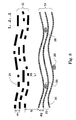
- Fig. 8 is a plan view of microscopic patterns 11 and 12 formed on the substrate 10 typically before recording information.
- a gap "G" between the microscopic pattern 11 and 12, that is, a gap “G” between the read only area 31 and the recording/reproducing area 32 is 25 ⁇ m.
- the microscopic patterns 11 corresponding to the read only area 31 is recorded spirally by the CLV method, that is, a group of pit 21, which is wobbled sinusoidally.
- a width of wobbling is 0.009 to 0.017 ⁇ m.
- An average track pitch P1 of the microscopic patterns 11 is 0.74 ⁇ m.
- the 8/16-modification method is utilized.
- a minimal pit length of the pit 21 is 0.4 ⁇ m.
- the recording/reproducing area 32 is composed of a sinusoidally wobbled groove 22 and an address pit 25 formed on a land 23, which is provided between each groove 22 with being adjacent to a groove wall. These groove 22 and address pit 25 is also formed in a spiral. A width of wobbling is 0.009 to 0.017 ⁇ m. An average track pitch P2 of the microscopic patterns 12 is 0.74 ⁇ m.
- the address pit 25 is a pit recorded with an address, which is useful when recording, and is recorded throughout the information recording medium from an innermost circumference area to an outermost circumference area in accordance with a certain rule. Recording is performed by forming a mark (not shown) in the groove 22.
- a minimal pit length L2 (not shown) of a recorded mark in the groove 2 is 0.4 ⁇ m as a same length as the minimal pit length L1.
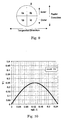
- Fig. 10 is a graph showing a relation between the depth d1 of the read only area 31 of the information recording medium and a push-pull signal output T1 according to the present invention.
- a vertical and horizontal axes represent a value of (d1 ⁇ n) divided by ⁇ , that is, (nd1/ ⁇ ) and a push-pull signal output T1 respectively.
- the T1 is defined by the sine function of the P1. According to Fig. 10, the (nd1/ ⁇ ) is specified to 0.03 through 0.22 so as to realize T1 ⁇ 0.1.
- a reproduction jitter which is fluctuation in a time axis direction, decreases as far as the (nd1/ ⁇ ) approaches to 0.25, so that it is proper for the (nd1/ ⁇ ) to be 0.12 through 0.22 in a depth.
- Fig. 11 is a graph showing a relation between the depth d2 of the recording/reproducing area 32 of the information recording medium and a push-pull signal output T2 according to the present invention.
- the T2 is defined by the sine function of the P2 as same as the T1. However, in a case of a groove, a value of the T2 is approximately twice a value of the T1. According to Fig. 11, the (nd2/ ⁇ ) is specified to 0.02 through 0.23 so as to realize T2 ⁇ 0.1.
- a jitter decreases in conjunction with reflectivity, which increase, as far as the (nd2/ ⁇ ) approaches to zero, so that it is proper for the (nd2/ ⁇ ) to be 0.02 through 0.12 in a depth.
- a reproduction jitter can be obtained in accordance with the Annex "F" of JIS-X-6241 (Japanese Industrial Standard). According to the Standard, a jitter is required to be not more than 8 %. In other words, if a jitter exceeds 8 %, reading out a reproduction signal is seriously affected by disturbance such as disk tilt.
- ranges of (nd1/ ⁇ ) and (nd2/ ⁇ ) are as follows:
- An information recording medium 2 has a cross sectional configuration shown in Fig. 3.
- the information recording medium 2 comprises a substrate 10 composed of polycarbonate, a recording layer 13 composed of a phase change material having reflectivity of more than 10 %, particularly, an alloy composed of antimony, tellurium, and a metal having a melting point of less than 1100 °C, and a resin layer 14. Further, the recording layer 13 actually comprises an alloy composed of silver, indium, antimony, and tellurium (AgInSbTe), for example.
- the alloy is sandwiched by dielectric such as ZnSSiO and further laminated by a reflection film of an aluminum alloy, and then they are formed as a recording layer having a reflectivity of 10 to 25 %.
- the resin layer 14 comprises polycarbonate having a refractive index "n" of 1.6 at the wavelength ⁇ of 405 nm.
- Microscopic patterns on a surface of the substrate 10 in both the read only area 31 and the recording/reproducing area 32 are recorded spirally by the CAV method with being wobbled sinusoidally.
- Other parameters are the same as those of the first embodiment except for an average track pitch such that P1 and P2 is 0.374 ⁇ m, wherein respective width of wobbling is 0.006 to 0.011 ⁇ m.
- the D8/15-modification method which is one variation of the 8/15-modulation method and disclosed in the Japanese Patent Application No 11-23316/1999, is utilized.
- a minimal pit length L1 and a minimal mark length L2 is 0.2 ⁇ m respectively.
- Fig. 12 is a plan view of an information recording medium in a card shape according to the present invention.
- Fig. 13 is a plan view of another information recording medium in a card shape according to the present invention.
- the information recording medium is exemplified by a disk shaped one.
- an information recording medium 101 in a card shape provided with a read only area 131 in a stripe and a recording/reproducing area 132 in a stripe can be utilized.
- an information recording medium 201 in a card shape provided with a read only area 231 in a ring shape and a recording/reproducing area 232 in a ring shape can also be utilized.
- a phase change recording material is utilized for the recording layer 13.
- the material is not limited to a phase change recording material.
- a magneto-optical recording material and a recordable type recording material such as a dye material can also be utilized.
- a wavelength of a laser beam utilized for reproducing or recording/reproducing is specified as 650 and 405 nm.
- a wavelength is not limited to them. Any length such as 830, 635, 515, 460, 430, and 370 nm, and their adjacent wavelength can be utilized.
- any NA such as 0.4, 0.45, 0.55, 0.65, 0.7, 0.75, 0.8, 0.85, and 0.9 other than 0.60 can be applicable.
- a lens having an NA of more than 1.0 which is represented by a solid immersion lens, can also be applicable.
- the information recording medium which comprises at least the read only area 31 and the recording/reproducing area 32, can perform a traverse reproduction over two areas by specifying push-pull signal outputs from the read only area 31 and the recording/reproducing area 32 to a predetermined range.
Landscapes
- Engineering & Computer Science (AREA)
- Software Systems (AREA)
- Theoretical Computer Science (AREA)
- Optical Recording Or Reproduction (AREA)
- Optical Record Carriers And Manufacture Thereof (AREA)
Abstract
Description
| T1 | Tracking |
| 0.08 | Disable |
| 0.10 | Enable |
| 0.15 | Enable |
| 0.18 | Enable |
| 0.25 | Enable |
| T2 | Tracking |
| 0.08 | Disable |
| 0.10 | Enable |
| 0.15 | Enable |
| 0.22 | Enable |
| 0.31 | Enable |
| 0.45 | Enable |
| T1 | T2 | T1/T2 | Traverse reproduction over areas |
| 0.10 | 0.10 | 1.0 | Enable |
| 0.10 | 0.20 | 0.5 | Enable |
| 0.10 | 0.25 | 0.4 | Disable |
| 0.15 | 0.22 | 0.7 | Enable |
| 0.20 | 0.12 | 1.7 | Disable |
| 0.20 | 0.13 | 1.5 | Enable |
| 0.20 | 0.28 | 0.7 | Enable |
| 0.20 | 0.40 | 0.5 | Enable |
| 0.20 | 0.45 | 0.4 | Disable |
| 0.22 | 0.16 | 1.4 | Enable |
| 0.25 | 0.16 | 1.6 | Disable |
| 0.25 | 0.17 | 1.5 | Enable |
| 0.25 | 0.25 | 1.0 | Enable |
| 0.25 | 0.34 | 0.7 | Enable |
| 0.25 | 0.44 | 0.6 | Enable |
Claims (5)
- An information recording medium comprising a substrate, a recording layer, and a resin layer, wherein said substrate is formed with a pit corresponding to a read only area and a groove corresponding to a recording/reproducing area without overlapping with each other, and wherein a reflectivity of said recording layer is more than 10 %, said information recording medium is characterized in that a push-pull signal output T1 reproduced from said read only area and another push-pull signal output T2 reproduced from said recording/reproducing area is more than 0.1 respectively and further 1.5 ≧ T1/T2 ≧ 0.5.
- The information recording medium in accordance with claim 1, wherein said recording layer comprises a phase change material so as for a reflectivity of said recording layer to be more than 15 %.
- The information recording medium in accordance with claim 1, wherein said information recording medium is characterized in that (nd1/λ) and (nd2/λ) is specified to be 0.12 to 0.22 and 0.02 to 0.12 respectively with defining a refractive index of said substrate at a reproduction wavelength λ to "n", a depth of said read only area to d1, and a depth of said recording/reproducing area to d2.
- The information recording medium in accordance with claim 1, wherein a track pitch P1 of said read only area and another track pitch P2 of said recording/reproducing area is equal to each other, and a minimal pit length L1 in said read only area and a minimal mark length L2 in said recording/reproducing area is equal to each other.
- The information recording medium in accordance with claim 1, wherein a gap between said read only area and said recording/reproducing area is specified to be less than 25 µm.
Priority Applications (7)
| Application Number | Priority Date | Filing Date | Title |
|---|---|---|---|
| EP06004923A EP1667126B1 (en) | 2000-04-10 | 2001-04-04 | Information recording medium |
| EP07016745A EP1870884B1 (en) | 2000-04-10 | 2001-04-04 | Information recording medium |
| EP07016743A EP1863018B1 (en) | 2000-04-10 | 2001-04-04 | Information recording medium |
| EP06004924A EP1667127B1 (en) | 2000-04-10 | 2001-04-04 | Information recording medium |
| EP07016746A EP1863020B1 (en) | 2000-04-10 | 2001-04-04 | Information recording medium |
| EP07016744A EP1863019B1 (en) | 2000-04-10 | 2001-04-04 | Information recording medium |
| EP09168741A EP2117001B1 (en) | 2000-04-10 | 2001-04-04 | Information recording medium |
Applications Claiming Priority (4)
| Application Number | Priority Date | Filing Date | Title |
|---|---|---|---|
| JP2000107736 | 2000-04-10 | ||
| JP2000107736 | 2000-04-10 | ||
| JP2000225094A JP2001357534A (en) | 2000-04-10 | 2000-07-26 | Information recording medium |
| JP2000225094 | 2000-07-26 |
Related Child Applications (2)
| Application Number | Title | Priority Date | Filing Date |
|---|---|---|---|
| EP06004924A Division EP1667127B1 (en) | 2000-04-10 | 2001-04-04 | Information recording medium |
| EP06004923A Division EP1667126B1 (en) | 2000-04-10 | 2001-04-04 | Information recording medium |
Publications (3)
| Publication Number | Publication Date |
|---|---|
| EP1146508A2 true EP1146508A2 (en) | 2001-10-17 |
| EP1146508A3 EP1146508A3 (en) | 2004-07-14 |
| EP1146508B1 EP1146508B1 (en) | 2006-05-24 |
Family
ID=26589768
Family Applications (8)
| Application Number | Title | Priority Date | Filing Date |
|---|---|---|---|
| EP01303202A Expired - Lifetime EP1146508B1 (en) | 2000-04-10 | 2001-04-04 | Information recording medium |
| EP07016743A Expired - Lifetime EP1863018B1 (en) | 2000-04-10 | 2001-04-04 | Information recording medium |
| EP06004924A Expired - Lifetime EP1667127B1 (en) | 2000-04-10 | 2001-04-04 | Information recording medium |
| EP07016746A Expired - Lifetime EP1863020B1 (en) | 2000-04-10 | 2001-04-04 | Information recording medium |
| EP09168741A Expired - Lifetime EP2117001B1 (en) | 2000-04-10 | 2001-04-04 | Information recording medium |
| EP07016745A Expired - Lifetime EP1870884B1 (en) | 2000-04-10 | 2001-04-04 | Information recording medium |
| EP07016744A Expired - Lifetime EP1863019B1 (en) | 2000-04-10 | 2001-04-04 | Information recording medium |
| EP06004923A Expired - Lifetime EP1667126B1 (en) | 2000-04-10 | 2001-04-04 | Information recording medium |
Family Applications After (7)
| Application Number | Title | Priority Date | Filing Date |
|---|---|---|---|
| EP07016743A Expired - Lifetime EP1863018B1 (en) | 2000-04-10 | 2001-04-04 | Information recording medium |
| EP06004924A Expired - Lifetime EP1667127B1 (en) | 2000-04-10 | 2001-04-04 | Information recording medium |
| EP07016746A Expired - Lifetime EP1863020B1 (en) | 2000-04-10 | 2001-04-04 | Information recording medium |
| EP09168741A Expired - Lifetime EP2117001B1 (en) | 2000-04-10 | 2001-04-04 | Information recording medium |
| EP07016745A Expired - Lifetime EP1870884B1 (en) | 2000-04-10 | 2001-04-04 | Information recording medium |
| EP07016744A Expired - Lifetime EP1863019B1 (en) | 2000-04-10 | 2001-04-04 | Information recording medium |
| EP06004923A Expired - Lifetime EP1667126B1 (en) | 2000-04-10 | 2001-04-04 | Information recording medium |
Country Status (4)
| Country | Link |
|---|---|
| US (24) | US6582793B2 (en) |
| EP (8) | EP1146508B1 (en) |
| JP (1) | JP2001357534A (en) |
| DE (7) | DE60131207T2 (en) |
Cited By (2)
| Publication number | Priority date | Publication date | Assignee | Title |
|---|---|---|---|---|
| EP1302937A3 (en) * | 2001-10-15 | 2006-10-25 | Victor Company Of Japan, Limited | Information recording medium |
| EP1525578A4 (en) * | 2002-06-28 | 2007-05-09 | Samsung Electronics Co Ltd | HIGHLY DENSITY REPRODUCTION OPTICAL DISC AND METHOD OF REPRODUCING DATA THEREFROM |
Families Citing this family (13)
| Publication number | Priority date | Publication date | Assignee | Title |
|---|---|---|---|---|
| DE60043406D1 (en) * | 1999-11-25 | 2010-01-07 | Victor Company Of Japan | Medium for recording optical information, and substrate and method for manufacturing the optical information recording medium |
| JP2001357534A (en) * | 2000-04-10 | 2001-12-26 | Victor Co Of Japan Ltd | Information recording medium |
| JP3922424B2 (en) * | 2000-07-25 | 2007-05-30 | パイオニア株式会社 | Optical recording medium, optical recording medium manufacturing apparatus, and optical recording medium manufacturing method |
| JP4300727B2 (en) * | 2001-10-09 | 2009-07-22 | ソニー株式会社 | DISC RECORDING MEDIUM, DISC DRIVE DEVICE, REPRODUCTION METHOD, AND DISC MANUFACTURING METHOD |
| JP2003257094A (en) * | 2002-02-28 | 2003-09-12 | Fuji Photo Film Co Ltd | Method for manufacturing optical information recording medium |
| US20050122890A1 (en) * | 2002-03-15 | 2005-06-09 | Kabushiki Kaisha Toshiba | Information recording medium and information recording/ reproducing device and method |
| JP2005078782A (en) * | 2003-09-04 | 2005-03-24 | Tdk Corp | Optical recording medium, its manufacturing method, and data recording and reproducing method for optical recording medium |
| US20060018240A1 (en) * | 2004-07-21 | 2006-01-26 | Charles Marshall | Digital media created using electron beam technology |
| US20060023573A1 (en) * | 2004-07-29 | 2006-02-02 | Rivera Manuel Jr | Method and system for enhanced optical medium reads |
| GB2433647B (en) * | 2005-12-20 | 2008-05-28 | Univ Southampton | Phase change memory materials, devices and methods |
| JP5367692B2 (en) * | 2006-02-08 | 2013-12-11 | タイレックス・インコーポレイテッド | Temporary stiffening mesh prosthesis |
| KR100870106B1 (en) * | 2006-03-21 | 2008-11-25 | 제일모직주식회사 | Optical disc using methyl methacrylate-acrylonitrile-butadiene-styrene copolymer resin |
| JP2013065363A (en) * | 2011-09-15 | 2013-04-11 | Sony Corp | Optical recording medium, recording device and recording method |
Family Cites Families (28)
| Publication number | Priority date | Publication date | Assignee | Title |
|---|---|---|---|---|
| US2002A (en) * | 1841-03-12 | Tor and planter for plowing | ||
| JPH0827992B2 (en) | 1989-07-24 | 1996-03-21 | 太陽誘電株式会社 | Optical information recording medium and optical information recording method using the same |
| US5204852A (en) | 1990-02-17 | 1993-04-20 | Victor Company Of Japan, Ltd. | Optical disc-like recoding medium and manufacturing method thereof |
| JPH04243019A (en) | 1991-01-17 | 1992-08-31 | Fuji Photo Film Co Ltd | Information recording medium |
| JPH05166229A (en) | 1991-12-11 | 1993-07-02 | Sony Corp | optical disk |
| JPH05298697A (en) | 1992-04-22 | 1993-11-12 | Ricoh Co Ltd | Optical disk and optical disk master exposure device |
| TW325185U (en) | 1994-03-22 | 1998-01-11 | Mitsubish Chem Corp | Optical disk |
| JP3703569B2 (en) | 1996-04-02 | 2005-10-05 | ソニー株式会社 | Optical recording medium, recording / reproducing method thereof, and recording / reproducing apparatus |
| JP3545893B2 (en) | 1996-12-05 | 2004-07-21 | 株式会社リコー | Optical information recording medium and master disc exposure method |
| JP3635514B2 (en) | 1997-02-24 | 2005-04-06 | パイオニア株式会社 | Information recording device |
| JPH10326435A (en) * | 1997-03-25 | 1998-12-08 | Sony Corp | Optical recording medium and optical disk device |
| US6163521A (en) * | 1997-04-16 | 2000-12-19 | Matsushita Electric Industrial Co., Ltd. | Disk having read-only and read-write areas |
| JPH10302310A (en) * | 1997-04-25 | 1998-11-13 | Sony Corp | Optical recording medium and optical disk device |
| JPH1166626A (en) * | 1997-08-18 | 1999-03-09 | Sony Corp | Optical disk and recording / reproducing method thereof |
| JPH1196579A (en) * | 1997-09-19 | 1999-04-09 | Tdk Corp | Recording and reproducing method of optical recording medium and optical recording medium |
| US6310854B1 (en) * | 1997-11-28 | 2001-10-30 | Yamaha Corporation | Optical disk having areas of different recording densities or functions |
| JP2000187842A (en) * | 1998-12-21 | 2000-07-04 | Taiyo Yuden Co Ltd | Method and device for optical information recording |
| EP1026670B1 (en) * | 1999-02-02 | 2001-12-12 | Matsushita Electric Industrial Co., Ltd. | Optical recording medium and recording/reproduction method and apparatus therefor |
| JP2000231745A (en) * | 1999-02-09 | 2000-08-22 | Sony Corp | Optical recording medium, master for producing optical recording medium, and method for producing the same |
| JP3512702B2 (en) | 1999-03-30 | 2004-03-31 | Hoya株式会社 | Method for manufacturing glass substrate for information recording medium and method for manufacturing information recording medium |
| JP2000293894A (en) * | 1999-04-07 | 2000-10-20 | Sony Corp | Optical recording medium |
| US6355916B1 (en) * | 1999-05-18 | 2002-03-12 | Alaris Medical Systems, Inc. | Closed loop system and method for heating a probe |
| US6212158B1 (en) * | 1999-06-01 | 2001-04-03 | Eastman Kodak Company | Hybrid optical disc construction |
| JP2000348388A (en) | 1999-06-04 | 2000-12-15 | Sharp Corp | Optical recording medium |
| TW476957B (en) * | 1999-09-08 | 2002-02-21 | Mitsubishi Chem Corp | Rewritable compact disk and manufacturing method thereof |
| DE60043406D1 (en) * | 1999-11-25 | 2010-01-07 | Victor Company Of Japan | Medium for recording optical information, and substrate and method for manufacturing the optical information recording medium |
| JP2001357534A (en) * | 2000-04-10 | 2001-12-26 | Victor Co Of Japan Ltd | Information recording medium |
| CN1220981C (en) * | 2001-10-15 | 2005-09-28 | 日本胜利株式会社 | information record carrier |
-
2000
- 2000-07-26 JP JP2000225094A patent/JP2001357534A/en active Pending
-
2001
- 2001-04-04 DE DE60131207T patent/DE60131207T2/en not_active Expired - Lifetime
- 2001-04-04 DE DE60140277T patent/DE60140277D1/en not_active Expired - Lifetime
- 2001-04-04 DE DE60140154T patent/DE60140154D1/en not_active Expired - Lifetime
- 2001-04-04 DE DE60140332T patent/DE60140332D1/en not_active Expired - Lifetime
- 2001-04-04 DE DE60139731T patent/DE60139731D1/en not_active Expired - Lifetime
- 2001-04-04 DE DE60131206T patent/DE60131206T2/en not_active Expired - Lifetime
- 2001-04-04 EP EP01303202A patent/EP1146508B1/en not_active Expired - Lifetime
- 2001-04-04 EP EP07016743A patent/EP1863018B1/en not_active Expired - Lifetime
- 2001-04-04 EP EP06004924A patent/EP1667127B1/en not_active Expired - Lifetime
- 2001-04-04 EP EP07016746A patent/EP1863020B1/en not_active Expired - Lifetime
- 2001-04-04 DE DE60119829T patent/DE60119829T2/en not_active Expired - Lifetime
- 2001-04-04 EP EP09168741A patent/EP2117001B1/en not_active Expired - Lifetime
- 2001-04-04 EP EP07016745A patent/EP1870884B1/en not_active Expired - Lifetime
- 2001-04-04 EP EP07016744A patent/EP1863019B1/en not_active Expired - Lifetime
- 2001-04-04 EP EP06004923A patent/EP1667126B1/en not_active Expired - Lifetime
- 2001-04-05 US US09/825,924 patent/US6582793B2/en not_active Expired - Fee Related
-
2003
- 2003-05-12 US US10/435,057 patent/US6744725B2/en not_active Expired - Fee Related
-
2004
- 2004-02-12 US US10/776,322 patent/US6925050B2/en not_active Expired - Fee Related
- 2004-02-12 US US10/776,212 patent/US7035199B2/en not_active Expired - Fee Related
-
2005
- 2005-06-22 US US11/157,856 patent/US7072284B2/en not_active Expired - Fee Related
- 2005-06-22 US US11/157,943 patent/US7197006B2/en not_active Expired - Fee Related
-
2006
- 2006-01-10 US US11/328,066 patent/US7385912B2/en not_active Expired - Fee Related
- 2006-01-10 US US11/328,064 patent/US7313084B2/en not_active Expired - Fee Related
- 2006-05-12 US US11/432,477 patent/US7898934B2/en not_active Expired - Lifetime
- 2006-05-12 US US11/432,481 patent/US7397756B2/en not_active Expired - Fee Related
-
2007
- 2007-10-20 US US11/875,877 patent/US7411892B2/en not_active Expired - Lifetime
- 2007-10-20 US US11/875,875 patent/US7570572B2/en not_active Expired - Lifetime
- 2007-10-20 US US11/875,869 patent/US7599280B2/en not_active Expired - Fee Related
- 2007-10-20 US US11/875,872 patent/US7471619B2/en not_active Expired - Lifetime
- 2007-10-20 US US11/875,868 patent/US7570571B2/en not_active Expired - Fee Related
- 2007-10-20 US US11/875,876 patent/US7567500B2/en not_active Expired - Lifetime
- 2007-10-20 US US11/875,874 patent/US7577083B2/en not_active Expired - Lifetime
- 2007-10-20 US US11/875,871 patent/US7577082B2/en not_active Expired - Lifetime
- 2007-10-20 US US11/875,878 patent/US7570573B2/en not_active Expired - Lifetime
- 2007-10-22 US US11/876,039 patent/US7580343B2/en not_active Expired - Lifetime
- 2007-10-22 US US11/876,049 patent/US7570574B2/en not_active Expired - Lifetime
-
2009
- 2009-07-20 US US12/505,658 patent/US7826335B2/en not_active Expired - Fee Related
- 2009-07-20 US US12/505,666 patent/US7817531B2/en not_active Expired - Fee Related
- 2009-07-20 US US12/505,650 patent/US7821911B2/en not_active Expired - Fee Related
Cited By (2)
| Publication number | Priority date | Publication date | Assignee | Title |
|---|---|---|---|---|
| EP1302937A3 (en) * | 2001-10-15 | 2006-10-25 | Victor Company Of Japan, Limited | Information recording medium |
| EP1525578A4 (en) * | 2002-06-28 | 2007-05-09 | Samsung Electronics Co Ltd | HIGHLY DENSITY REPRODUCTION OPTICAL DISC AND METHOD OF REPRODUCING DATA THEREFROM |
Also Published As
Similar Documents
| Publication | Publication Date | Title |
|---|---|---|
| US7570573B2 (en) | Information recording medium |
Legal Events
| Date | Code | Title | Description |
|---|---|---|---|
| PUAI | Public reference made under article 153(3) epc to a published international application that has entered the european phase |
Free format text: ORIGINAL CODE: 0009012 |
|
| AK | Designated contracting states |
Kind code of ref document: A2 Designated state(s): AT BE CH CY DE DK ES FI FR GB GR IE IT LI LU MC NL PT SE TR |
|
| AX | Request for extension of the european patent |
Free format text: AL;LT;LV;MK;RO;SI |
|
| PUAL | Search report despatched |
Free format text: ORIGINAL CODE: 0009013 |
|
| AK | Designated contracting states |
Kind code of ref document: A3 Designated state(s): AT BE CH CY DE DK ES FI FR GB GR IE IT LI LU MC NL PT SE TR |
|
| AX | Request for extension of the european patent |
Extension state: AL LT LV MK RO SI |
|
| 17P | Request for examination filed |
Effective date: 20040806 |
|
| AKX | Designation fees paid |
Designated state(s): DE FR GB |
|
| 17Q | First examination report despatched |
Effective date: 20050421 |
|
| GRAP | Despatch of communication of intention to grant a patent |
Free format text: ORIGINAL CODE: EPIDOSNIGR1 |
|
| GRAS | Grant fee paid |
Free format text: ORIGINAL CODE: EPIDOSNIGR3 |
|
| GRAA | (expected) grant |
Free format text: ORIGINAL CODE: 0009210 |
|
| AK | Designated contracting states |
Kind code of ref document: B1 Designated state(s): DE FR GB |
|
| REG | Reference to a national code |
Ref country code: GB Ref legal event code: FG4D |
|
| REF | Corresponds to: |
Ref document number: 60119829 Country of ref document: DE Date of ref document: 20060629 Kind code of ref document: P |
|
| ET | Fr: translation filed | ||
| PLBE | No opposition filed within time limit |
Free format text: ORIGINAL CODE: 0009261 |
|
| STAA | Information on the status of an ep patent application or granted ep patent |
Free format text: STATUS: NO OPPOSITION FILED WITHIN TIME LIMIT |
|
| 26N | No opposition filed |
Effective date: 20070227 |
|
| REG | Reference to a national code |
Ref country code: DE Ref legal event code: R082 Ref document number: 60119829 Country of ref document: DE Representative=s name: 2K PATENTANWAELTE BLASBERG KEWITZ & REICHEL, P, DE |
|
| REG | Reference to a national code |
Ref country code: DE Ref legal event code: R081 Ref document number: 60119829 Country of ref document: DE Owner name: JVC KENWOOD CORPORATION, JP Free format text: FORMER OWNER: VICTOR COMPANY OF JAPAN, LTD., YOKOHAMA, JP Effective date: 20120430 Ref country code: DE Ref legal event code: R082 Ref document number: 60119829 Country of ref document: DE Representative=s name: 2K PATENTANWAELTE BLASBERG KEWITZ & REICHEL, P, DE Effective date: 20120430 Ref country code: DE Ref legal event code: R082 Ref document number: 60119829 Country of ref document: DE Representative=s name: 2K PATENTANWAELTE BLASBERG KEWITZ & REICHEL PA, DE Effective date: 20120430 Ref country code: DE Ref legal event code: R081 Ref document number: 60119829 Country of ref document: DE Owner name: JVC KENWOOD CORPORATION, YOKOHAMA-SHI, JP Free format text: FORMER OWNER: VICTOR COMPANY OF JAPAN, LTD., YOKOHAMA, KANAGAWA, JP Effective date: 20120430 |
|
| REG | Reference to a national code |
Ref country code: FR Ref legal event code: TP Owner name: JVC KENWOOD CORPORATION, JP Effective date: 20120705 |
|
| REG | Reference to a national code |
Ref country code: GB Ref legal event code: 732E Free format text: REGISTERED BETWEEN 20140403 AND 20140409 |
|
| REG | Reference to a national code |
Ref country code: FR Ref legal event code: PLFP Year of fee payment: 16 |
|
| REG | Reference to a national code |
Ref country code: FR Ref legal event code: PLFP Year of fee payment: 17 |
|
| REG | Reference to a national code |
Ref country code: FR Ref legal event code: PLFP Year of fee payment: 18 |
|
| PGFP | Annual fee paid to national office [announced via postgrant information from national office to epo] |
Ref country code: GB Payment date: 20200325 Year of fee payment: 20 |
|
| PGFP | Annual fee paid to national office [announced via postgrant information from national office to epo] |
Ref country code: FR Payment date: 20200312 Year of fee payment: 20 |
|
| PGFP | Annual fee paid to national office [announced via postgrant information from national office to epo] |
Ref country code: DE Payment date: 20200325 Year of fee payment: 20 |
|
| REG | Reference to a national code |
Ref country code: DE Ref legal event code: R071 Ref document number: 60119829 Country of ref document: DE |
|
| REG | Reference to a national code |
Ref country code: GB Ref legal event code: PE20 Expiry date: 20210403 |
|
| PG25 | Lapsed in a contracting state [announced via postgrant information from national office to epo] |
Ref country code: GB Free format text: LAPSE BECAUSE OF EXPIRATION OF PROTECTION Effective date: 20210403 |