EP1146327B1 - Pressure measurement instrument - Google Patents
Pressure measurement instrument Download PDFInfo
- Publication number
- EP1146327B1 EP1146327B1 EP01107853A EP01107853A EP1146327B1 EP 1146327 B1 EP1146327 B1 EP 1146327B1 EP 01107853 A EP01107853 A EP 01107853A EP 01107853 A EP01107853 A EP 01107853A EP 1146327 B1 EP1146327 B1 EP 1146327B1
- Authority
- EP
- European Patent Office
- Prior art keywords
- fluid
- transducer
- valve
- test port
- pressure measurement
- Prior art date
- Legal status (The legal status is an assumption and is not a legal conclusion. Google has not performed a legal analysis and makes no representation as to the accuracy of the status listed.)
- Expired - Lifetime
Links
- 238000009530 blood pressure measurement Methods 0.000 title claims description 18
- 239000012530 fluid Substances 0.000 claims abstract description 97
- 238000012360 testing method Methods 0.000 claims abstract description 65
- 238000000034 method Methods 0.000 claims description 16
- 230000007704 transition Effects 0.000 claims 1
- 238000012544 monitoring process Methods 0.000 description 13
- 239000000523 sample Substances 0.000 description 12
- 238000005259 measurement Methods 0.000 description 7
- 238000010586 diagram Methods 0.000 description 3
- 230000007246 mechanism Effects 0.000 description 3
- 230000000694 effects Effects 0.000 description 2
- 238000009434 installation Methods 0.000 description 2
- XUIMIQQOPSSXEZ-UHFFFAOYSA-N Silicon Chemical compound [Si] XUIMIQQOPSSXEZ-UHFFFAOYSA-N 0.000 description 1
- 230000010354 integration Effects 0.000 description 1
- 238000012986 modification Methods 0.000 description 1
- 230000004048 modification Effects 0.000 description 1
- 238000012806 monitoring device Methods 0.000 description 1
- 238000007789 sealing Methods 0.000 description 1
- 229910052710 silicon Inorganic materials 0.000 description 1
- 239000010703 silicon Substances 0.000 description 1
- 238000006467 substitution reaction Methods 0.000 description 1
Images



Classifications
-
- G—PHYSICS
- G01—MEASURING; TESTING
- G01L—MEASURING FORCE, STRESS, TORQUE, WORK, MECHANICAL POWER, MECHANICAL EFFICIENCY, OR FLUID PRESSURE
- G01L19/00—Details of, or accessories for, apparatus for measuring steady or quasi-steady pressure of a fluent medium insofar as such details or accessories are not special to particular types of pressure gauges
- G01L19/0007—Fluidic connecting means
- G01L19/0015—Fluidic connecting means using switching means
-
- G—PHYSICS
- G01—MEASURING; TESTING
- G01L—MEASURING FORCE, STRESS, TORQUE, WORK, MECHANICAL POWER, MECHANICAL EFFICIENCY, OR FLUID PRESSURE
- G01L27/00—Testing or calibrating of apparatus for measuring fluid pressure
- G01L27/002—Calibrating, i.e. establishing true relation between transducer output value and value to be measured, zeroing, linearising or span error determination
- G01L27/005—Apparatus for calibrating pressure sensors
Definitions
- the present invention relates to measurement instruments and, more particularly, to a flexible, efficient, and easy-to-use mechanical-to-electrical measurement instrument.
- Measurement instruments are growing in popularity because of their small size and increasing functionality. However, despite the advances of size and functionality, many mechanical-to-electrical measurement instruments still require continual monitoring and calibration to retain measurement accuracy.
- an electronic device for measuring pressure must often be compared to a known reference, such as a mechanical pressure standard. This is often due to the inability of a pressure to electric transducer or other component(s) to maintain an accurate output.
- a known reference such as a mechanical pressure standard.
- many such electronic devices include electronic output adjustments.
- potentiometers or variable resistors are often included to allow a user to monitor and calibrate these electronic devices to a known reference.
- an electronic pressure gauge goes through a routine monitoring cycle. Periodically, the output of the electronic pressure gauge is recorded. The pressure source is then measured by a reference pressure standard. If the output from the reference pressure standard is equal to the output from the electronic pressure gauge, then the gauge is assumed to be operating properly.
- the electronic pressure gauge may also (or alternatively) go through a routine calibration cycle.
- a typical calibration cycle requires that the electronic pressure gauge be removed from the pressure source and connected to a source with a known output.
- the electronic pressure gauge must provide an output that is equal (within limits) to the known output.
- The-known output can be adjusted throughout an operating range to calibrate the electronic pressure gauge across that range.
- US-A-3,777,546 discloses an electronic instrument for providing an electrical output responsive to a pressure of a first fluid, having an operation input for receiving the first fluid, a pressure-to-electrical transducer for converting a pressure of a receiving fluid to an electrical signal, a mechanical test port with a test input for receiving a second fluid, and a moveable valve for selectively directing one of either the first or second fluid to the transducer, so that when the valve is in a first position, the first fluid is directed to the transducer, and when the valve is in a second position, the second fluid is directed to the transducer.
- this document addresses the problem of providing a selector valve which switches which fluids are routed to the transducer.
- the invention relates to a pressure measurement instrument as claimd in claim 1 and to a method as claimed in claim 14.
- the at least one fluid when the valve is in the second position, the at least one fluid is also directed to the transducer.
- At least one fluid is continually directed to the transducer.
- the first and second fluids are diverted from the transducer.
- the conduits are operable to direct two different fluids from the mechanical test port to the transducer.
- the conduits are operable only when test lines have been engaged with the mechanical test port.
- the mechanical test port is operable to rotate the valve by engaging test lines with the mechanical test port and rotating the test lines.
- the valve includes a spring for returning the valve to the first position whenever the test lines are disengaged with the mechanical test port.
- the instrument includes an electrical test port for receiving an external electrical test device, thereby allowing the device to monitor an output of the transducer.
- a DIN rail clip is included for mounting the instrument onto a pair of DIN rails.
- the reference numeral 10 refers to a measurement system embodying features of the present invention.
- the measurement instrument 10 includes two electronic pressure instruments 12 and 14.
- Each instrument 12, 14 includes a plurality of faces, including a front face 12f, 14f, a back face 12b, 14b, and a top face 12t, 14t, respectively.
- the two electronic pressure instruments 12, 14 are similarly configured, except where explicitly describe below. Therefore, to describe the similar configuration, only the electronic pressure instrument 14 will be discussed.
- the back face 14b of the electronic pressure instrument includes a mounting system.
- a DIN rail clip 16 is used to selectively mount the instrument 14 to a mounting rail 18.
- the mounting rail 18 includes a rail channel 20 in a conventional DIN rail geometry that allows standard components to be mounted to the rails.
- DIN rails are used for items such as junction boxes and circuit breakers, but are used in the present embodiment to attach the two electronic pressure instruments 12 and 14.
- a system includes some type of programmable controller along with other associated test devices, such as low pressure differential sensors.
- Even the smallest sensor available uses a two hole mounting scheme to affix the sensor to the cabinet.
- Several actions result from this conventional mounting scheme. The installer must drill and tap two holes, by hand, for each transducer to be mounted on a panel.
- the panel is quite large because of the amount of equipment that is assembled thereon. The fact that several transducers are used often makes the panel even larger because the end to end mounting technique used (a result of the transducer package) forces the width of the panel to grow. These all add to the cost of installation.
- the top face 14t of the electronic pressure instrument 14 includes two fluid inputs 22, 24.
- the inputs 22, 24 are for connecting with two fluid sources (not shown) in a leak proof manner and directing the fluid into the pressure instrument 14. It is understood that discussion of fluid flow and fluid movement are, in the present embodiment, directed towards fluid pressure measurement.
- the front face 14f of the electronic pressure instrument 14 includes a plurality of indicators 30.
- the indicators 30 are light emitting diodes.
- the front face 14f also includes two test ports 32a, 32b (collectively designated with the numeral 32).
- the test ports 32 allow two probes (not shown) to be inserted to measure an electrical output of the pressure instrument 14.
- the probes may form a serial or parallel connection with the test ports 32, as needed.
- the front face 14f also includes a plurality of calibration devices 34a, 34b.
- the calibration devices are two potentiometers that can be manually adjusted.
- the calibration devices can be used for a calibration mode, discussed in greater detail, below.
- the front face 14f also includes a plurality of electrical outputs 36, 38.
- the electrical outputs 36, 38 produce the electrical voltage differential (or current, as desired) responsive to a pressure differential from the two inputs 22, 24. This operation is also discussed in greater detail, below.
- the two electronic pressure instruments 12, 14 are different in that the front face 14f of the instrument 14 includes a valve port 40.
- the valve port 40 allows an external probe (not shown) to be selectively connected to the instrument 14 and to perform various monitoring and/or calibration activities. These activities are discussed in greater detail, below.
- FIG. 2 and 3 another embodiment of an electronic pressure instrument is designated with the reference numeral 50.
- Components of the electronic pressure instrument 50 that are identical to those of electronic pressure instruments 12 and 14 (Fig. 1) are similarly numbered.
- the electronic pressure instrument 50 includes a plastic shell 52 with a plurality of faces, including a front face 52f.
- the front face 52f includes a plurality of indicators 54.
- the indicators 54 are light emitting diodes (LED's) that are activated to indicate the conditions identified in Table 1, below.
- Table 1 LED Condition 54a the pressure differential is positive, and exceeds a preset limit 54b the pressure differential is within positive operating limits 54c there is no pressure differential 54d the pressure differential is within negative operating limits 54e the pressure differential is negative, and exceeds a preset limit
- the front face 52f also includes two test ports 56a, 56b.
- the test ports 56a, 56b allow two probes 57a, 57b, respectively, to be inserted to measure an electrical output of the pressure instrument 50.
- the probes may form a serial or parallel connection with the test ports 56a, 56b, as needed.
- a silicon diode (not shown) can be placed inside the pressure instrument 50 between the two ports 56a, 56b.
- the low impedance of an amp meter shunts all the current through the meter. This allows a user to know the current output of the sensor, in case an electrical problem exists elsewhere in the electronic pressure instrument 50, without disconnecting the instrument.
- the front face 52f also includes a plurality of electrical calibration devices 58a, 58b.
- the electrical calibration devices are two potentiometers that can be manually adjusted.
- the calibration devices 58a, 58b can be used for a calibration mode, discussed in greater detail, below.
- the front face 52f also includes a plurality of electrical outputs.
- three electrical lines 62a, 62b, 62c are connected to three screw-type terminals 64a, 64b, 64c, respectively.
- the electrical lines 62a, 62b, 62c further connect to another electrical device (not shown) to provided an electrical representation of the pressure difference between two fluids flowing through the two fluid inputs 22, 24.
- the terminals 64a, 64b, 64c can be used to attach additional electrical lines, test equipment, or facilitate other applications.
- the electronic pressure instrument 50 includes a pressure transducer 70 that receives fluid from two fluid tubes 72, 74, measures the pressure difference between the fluids in the tubes, and converts the pressure difference to an electrical output.
- the pressure transducer 70 may be a sensor device as described in U.S. Patent No. 4,996,627.
- the electrical output is then provided to the two electrical lines 62a, 62b and two screw-type terminals 64a, 64b.
- the third electrical line 62c and third terminal 64c provide an electrical common voltage.
- the valve port 40 includes two apertures 82a, 82b that are adapted to receive a probe 84.
- the probe 84 includes two test lines 86a, 86b, for engaging with the apertures 82a, 82b, respectively.
- the apertures 82a, 82b remain leak proof unless and until the test lines 86a, 86b are inserted. At that time, fluid may flow through the apertures 82a, 82b and the test lines 86a, 86b, respectively.
- the probe 84 includes a hand unit 87 so that a person's hand can easily insert and remove the test lines 86a, 86b into the valve port 40.
- the probe 84 is configured with two depressions 88, 90 so that the probe can be easily rotated, thereby rotating the valve port 40 when engaged.
- the valve port 40 is attached to a rotatable selecting valve cylinder 100.
- the valve cylinder 100 includes a plurality of apertures for selectively connecting the valve port 40, the two fluid tubes 72, 74, and the two fluid inputs 22, 24.
- the electronic pressure instrument 50 can be placed in various modes of operation: a normal mode, a monitor mode, and a calibrate mode.
- the electronic pressure instrument 50 is in the normal operation mode when the valve port 40, and hence the valve cylinder 100, is rotated into a first position, as illustrated.
- the valve port 40 may be easily rotated by engaging the probe 84 (Fig. 3) with the valve port and manually turning the probe accordingly.
- apertures 102a, 102b align with the two fluid inputs 22, 24, respectively
- apertures 104a, 104b align with the two fluid tubes 72, 74, respectively.
- Aperture 102a is connected to aperture 104a by an internal routing mechanism 106a
- aperture 102b is connected to aperture 104b by an internal routing mechanism 106b.
- the routing mechanisms are conduits formed in the valve cylinder 100. Fluid can thereby flow from the pressure source 107, through the fluid inputs 22, 24, through the conduits 106a, 106b, through the fluid tubes 72, 74, and to the sensor 70.
- the electronic pressure instrument 50 is in the monitoring operation mode when the valve port 40, and hence the valve cylinder 100, is rotated into a second position, as illustrated.
- apertures 108a, 108b align with the two fluid inputs 22, 24, respectively
- apertures 110a, 110b align with the two fluid tubes 72, 74, respectively.
- Aperture 108a is connected to aperture 110a by a conduit 112a
- aperture 108b is connected to aperture 110b by a conduit 112b.
- Conduit 112a is also connected to aperture 82a and conduit 112b is also connected to aperture 82b, both on the valve port 40.
- Fluid can thereby flow from the pressure source 107, through the fluid inputs 22, 24, through the conduits 112a, 112b, through the fluid tubes 72, 74, and to the sensor 70.
- the fluid can also flow through the conduits 112a, 112b, through the test lines 86a, 86b, and to a monitoring device (Fig. 2).
- the electronic pressure instrument 50 is in the calibrating operation mode when the valve port 40, and hence the valve cylinder 100, is rotated into a third position, as illustrated.
- the two fluid inputs 22, 24 (and hence the pressure source 107) are shut off from the two fluid tubes 72, 74, respectively.
- Apertures 114a, 114b in the valve cylinder 100 align with the two fluid tubes 72, 74, respectively and connected to apertures 82a, 82b through conduits 116a, 116b, respectively. Fluid can thereby flow to and from a calibration device through the test lines 86a, 86b (Fig. 2), through the conduits 116a, 116b, and to the sensor 70.
- test lines 86a, 86b are inserted, monitoring and/or calibration can be readily performed.
- a spring 120 returns the valve cylinder 100 to the first position, so that after monitoring mode or calibration mode operation has been completed, the test lines 86a, 86b can be simply removed from the apertures 82a, 82b and the pressure instrument 50 returns to normal operating mode.
- valve cylinder 120 has many of similar elements as valve cylinder 100 (Figs 4-6), the similar elements retaining the same reference numeral. However, the valve cylinder 120 allows a fluid to continuously flow from the fluid inputs 22, 24 to the sensor 70 when the valve cylinder is being rotated from the operating mode position to the monitor mode position (illustrated).
- two apertures 122a, 122b connect with the fluid input 22 when the valve cylinder 120 is in the monitor mode position, and only one aperture 122a connects with the fluid input 22 when the valve cylinder 120 is in the operating mode position.
- the aperture 122a is beyond the sealing portion of an o-ring 123a surrounding the aperture 122b. That is, the aperture 122a remains connected to the fluid input 22 while the valve cylinder is being rotated from operating mode to monitoring mode position. In this way, a fluid 124 can flow from the fluid source, through the aperture 122a, through the aperture 104a, and to the sensor 70.
- the aperture 122a is surrounded by two o-rings 125a, 125b so that the fluid 124 is securely directed to the aperture 104a.
- the aperture 122b is only connected to the fluid input 22 when the valve cylinder is in monitoring mode. In this way, a fluid 126 can flow from the fluid source, through the aperture slot 122b (only when the valve cylinder is in the monitoring mode), through a conduit 128, and through the aperture 82a.
- a fluid130 can continuously flow from the fluid input 24, through an aperture 132a and through the aperture 104b.
- the aperture 132a is surrounded by two o-rings 125b, 125c so that the fluid 130 is continually directed towards the aperture 104b while the valve cylinder 120 is being rotated between the operating and monitoring modes.
- a fluid 134 is directed through an aperture 132b, through a conduit 136, and through the aperture 82b.
- An o-ring 123b surrounds the aperture 132b so that the fluid 134 flows only when the valve cylinder is in the monitoring mode.
Landscapes
- Physics & Mathematics (AREA)
- General Physics & Mathematics (AREA)
- Chemical & Material Sciences (AREA)
- Analytical Chemistry (AREA)
- Measuring Fluid Pressure (AREA)
- Glass Compositions (AREA)
Abstract
Description
- The present invention relates to measurement instruments and, more particularly, to a flexible, efficient, and easy-to-use mechanical-to-electrical measurement instrument.
- Measurement instruments are growing in popularity because of their small size and increasing functionality. However, despite the advances of size and functionality, many mechanical-to-electrical measurement instruments still require continual monitoring and calibration to retain measurement accuracy.
- For example, an electronic device for measuring pressure (an electronic pressure gauge) must often be compared to a known reference, such as a mechanical pressure standard. This is often due to the inability of a pressure to electric transducer or other component(s) to maintain an accurate output. As a result, many such electronic devices include electronic output adjustments. For example, potentiometers or variable resistors are often included to allow a user to monitor and calibrate these electronic devices to a known reference.
- In typical operation, an electronic pressure gauge goes through a routine monitoring cycle. Periodically, the output of the electronic pressure gauge is recorded. The pressure source is then measured by a reference pressure standard. If the output from the reference pressure standard is equal to the output from the electronic pressure gauge, then the gauge is assumed to be operating properly.
- The electronic pressure gauge may also (or alternatively) go through a routine calibration cycle. A typical calibration cycle requires that the electronic pressure gauge be removed from the pressure source and connected to a source with a known output. To pass calibration, the electronic pressure gauge must provide an output that is equal (within limits) to the known output. The-known output can be adjusted throughout an operating range to calibrate the electronic pressure gauge across that range.
- US-A-3,777,546 discloses an electronic instrument for providing an electrical output responsive to a pressure of a first fluid, having an operation input for receiving the first fluid, a pressure-to-electrical transducer for converting a pressure of a receiving fluid to an electrical signal, a mechanical test port with a test input for receiving a second fluid, and a moveable valve for selectively directing one of either the first or second fluid to the transducer, so that when the valve is in a first position, the first fluid is directed to the transducer, and when the valve is in a second position, the second fluid is directed to the transducer. Thus, this document addresses the problem of providing a selector valve which switches which fluids are routed to the transducer.
- What is needed is an electronic pressure gauge that is easy to monitor and/or calibrate, and is relatively small and functional.
- The invention relates to a pressure measurement instrument as claimd in claim 1 and to a method as claimed in claim 14.
- In some embodiments, when the valve is in the second position, the at least one fluid is also directed to the transducer.
- In some embodiments, when the valve is being rotated to the second position, at least one fluid is continually directed to the transducer.
- In some embodiments, when the valve is in a third position, the first and second fluids are diverted from the transducer. In some embodiments, when the valve is in the third position, the conduits are operable to direct two different fluids from the mechanical test port to the transducer.
- In some embodiments, the conduits are operable only when test lines have been engaged with the mechanical test port.
- In some embodiments, the mechanical test port is operable to rotate the valve by engaging test lines with the mechanical test port and rotating the test lines.
- In some embodiments, the valve includes a spring for returning the valve to the first position whenever the test lines are disengaged with the mechanical test port.
- In some embodiments, the instrument includes an electrical test port for receiving an external electrical test device, thereby allowing the device to monitor an output of the transducer.
- In some embodiments, a DIN rail clip is included for mounting the instrument onto a pair of DIN rails.
-
- Fig. 1 is an isometric view of two electronic pressure instruments according to different embodiments of the present invention.
- Fig. 2 is an isometric cut-away view of one of the electronic pressure instruments of Fig. 1.
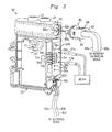
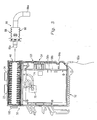
- Fig. 3 is a side cross-sectional view of the electronic pressure instrument of Fig. 2.
- Figs. 4a and 4b are functional diagrams of a valve cylinder of the electronic pressure instrument of Fig. 2 being in an operating mode position.
- Figs. 5a and 5b are functional diagrams of a valve cylinder of the electronic pressure instrument of Fig. 2 being in a monitoring mode position.
- Figs. 6a and 6b are functional diagrams of a valve cylinder of the electronic pressure instrument of Fig. 2 being in a calibrating mode position.
- Fig. 7 is an isometric view of another embodiment of a valve cylinder.
- In Fig. 1, the
reference numeral 10 refers to a measurement system embodying features of the present invention. In one embodiment, themeasurement instrument 10 includes two electronic pressure instruments 12 and 14. Each instrument 12, 14 includes a plurality of faces, including afront face back face top face - The
back face 14b of the electronic pressure instrument includes a mounting system. In one embodiment, aDIN rail clip 16 is used to selectively mount the instrument 14 to amounting rail 18. Themounting rail 18 includes arail channel 20 in a conventional DIN rail geometry that allows standard components to be mounted to the rails. Conventionally, DIN rails are used for items such as junction boxes and circuit breakers, but are used in the present embodiment to attach the two electronic pressure instruments 12 and 14. - The integration of the DIN
rail clip 16 for themounting rail 18 directly addresses the cost of installation by reducing labor and the potential size of the electronic pressure instruments 12 and 14. Conventionally, a system includes some type of programmable controller along with other associated test devices, such as low pressure differential sensors. Even the smallest sensor available uses a two hole mounting scheme to affix the sensor to the cabinet. Several actions result from this conventional mounting scheme. The installer must drill and tap two holes, by hand, for each transducer to be mounted on a panel. The panel is quite large because of the amount of equipment that is assembled thereon. The fact that several transducers are used often makes the panel even larger because the end to end mounting technique used (a result of the transducer package) forces the width of the panel to grow. These all add to the cost of installation. - The
top face 14t of the electronic pressure instrument 14 includes twofluid inputs inputs - The
front face 14f of the electronic pressure instrument 14 includes a plurality ofindicators 30. In one embodiment, theindicators 30 are light emitting diodes. Thefront face 14f also includes two test ports 32a, 32b (collectively designated with the numeral 32). Thetest ports 32 allow two probes (not shown) to be inserted to measure an electrical output of the pressure instrument 14. The probes may form a serial or parallel connection with thetest ports 32, as needed. - The
front face 14f also includes a plurality ofcalibration devices 34a, 34b. In one embodiment, the calibration devices are two potentiometers that can be manually adjusted. The calibration devices can be used for a calibration mode, discussed in greater detail, below. Thefront face 14f also includes a plurality ofelectrical outputs electrical outputs inputs - The two electronic pressure instruments 12, 14 are different in that the
front face 14f of the instrument 14 includes avalve port 40. Thevalve port 40 allows an external probe (not shown) to be selectively connected to the instrument 14 and to perform various monitoring and/or calibration activities. These activities are discussed in greater detail, below. - Referring now to Figs. 2 and 3, another embodiment of an electronic pressure instrument is designated with the
reference numeral 50. Components of theelectronic pressure instrument 50 that are identical to those of electronic pressure instruments 12 and 14 (Fig. 1) are similarly numbered. - The
electronic pressure instrument 50 includes aplastic shell 52 with a plurality of faces, including afront face 52f. Thefront face 52f includes a plurality ofindicators 54. In one embodiment, theindicators 54 are light emitting diodes (LED's) that are activated to indicate the conditions identified in Table 1, below.Table 1 LED Condition 54a the pressure differential is positive, and exceeds a preset limit 54b the pressure differential is within positive operating limits 54c there is no pressure differential 54d the pressure differential is within negative operating limits 54e the pressure differential is negative, and exceeds a preset limit - The
front face 52f also includes twotest ports 56a, 56b. Thetest ports 56a, 56b allow twoprobes 57a, 57b, respectively, to be inserted to measure an electrical output of thepressure instrument 50. The probes may form a serial or parallel connection with thetest ports 56a, 56b, as needed. In the case of a serial connection for measuring electrical current, a silicon diode (not shown) can be placed inside thepressure instrument 50 between the twoports 56a, 56b. The low impedance of an amp meter shunts all the current through the meter. This allows a user to know the current output of the sensor, in case an electrical problem exists elsewhere in theelectronic pressure instrument 50, without disconnecting the instrument. - The
front face 52f also includes a plurality ofelectrical calibration devices 58a, 58b. In one embodiment, the electrical calibration devices are two potentiometers that can be manually adjusted. Thecalibration devices 58a, 58b can be used for a calibration mode, discussed in greater detail, below. - The
front face 52f also includes a plurality of electrical outputs. In the present embodiment, threeelectrical lines electrical lines fluid inputs - The
electronic pressure instrument 50 includes apressure transducer 70 that receives fluid from twofluid tubes pressure transducer 70 may be a sensor device as described in U.S. Patent No. 4,996,627. The electrical output is then provided to the twoelectrical lines electrical line 62c and third terminal 64c provide an electrical common voltage. - The
valve port 40 includes twoapertures probe 84. Theprobe 84 includes twotest lines apertures apertures test lines apertures test lines probe 84 includes ahand unit 87 so that a person's hand can easily insert and remove thetest lines valve port 40. Also, the probe 84is configured with twodepressions valve port 40 when engaged. - The
valve port 40 is attached to a rotatable selectingvalve cylinder 100. Thevalve cylinder 100 includes a plurality of apertures for selectively connecting thevalve port 40, the twofluid tubes fluid inputs valve port 40, and thus thevalve cylinder 100, theelectronic pressure instrument 50 can be placed in various modes of operation: a normal mode, a monitor mode, and a calibrate mode. - Referring to Figs. 4a and 4b, the
electronic pressure instrument 50 is in the normal operation mode when thevalve port 40, and hence thevalve cylinder 100, is rotated into a first position, as illustrated. Thevalve port 40 may be easily rotated by engaging the probe 84 (Fig. 3) with the valve port and manually turning the probe accordingly. In this first position, apertures 102a, 102b align with the twofluid inputs apertures fluid tubes Aperture 102a is connected toaperture 104a by aninternal routing mechanism 106a, andaperture 102b is connected toaperture 104b by aninternal routing mechanism 106b. In the present embodiment, the routing mechanisms are conduits formed in thevalve cylinder 100. Fluid can thereby flow from thepressure source 107, through thefluid inputs conduits fluid tubes sensor 70. - Referring to Figs. 5a and 5b, the
electronic pressure instrument 50 is in the monitoring operation mode when thevalve port 40, and hence thevalve cylinder 100, is rotated into a second position, as illustrated. In this second position, apertures 108a, 108b align with the twofluid inputs apertures 110a, 110b align with the twofluid tubes conduit 112a, andaperture 108b is connected toaperture 110b by aconduit 112b.Conduit 112a is also connected toaperture 82a andconduit 112b is also connected toaperture 82b, both on thevalve port 40. Fluid can thereby flow from thepressure source 107, through thefluid inputs conduits fluid tubes sensor 70. The fluid can also flow through theconduits test lines - Referring to Figs. 6a and 6b, the
electronic pressure instrument 50 is in the calibrating operation mode when thevalve port 40, and hence thevalve cylinder 100, is rotated into a third position, as illustrated. In this third position, the twofluid inputs 22, 24 (and hence the pressure source 107) are shut off from the twofluid tubes Apertures 114a, 114b in thevalve cylinder 100 align with the twofluid tubes apertures conduits test lines conduits sensor 70. - With the above described monitoring and calibration mode operations, no additional devices are required and no manual disconnections must be performed. Once the
test lines spring 120 returns thevalve cylinder 100 to the first position, so that after monitoring mode or calibration mode operation has been completed, thetest lines apertures pressure instrument 50 returns to normal operating mode. - Referring now to Fig. 7, another embodiment of the valve cylinder is identified with the
reference numeral 120. Thevalve cylinder 120 has many of similar elements as valve cylinder 100 (Figs 4-6), the similar elements retaining the same reference numeral. However, thevalve cylinder 120 allows a fluid to continuously flow from thefluid inputs sensor 70 when the valve cylinder is being rotated from the operating mode position to the monitor mode position (illustrated). - To accomplish the continuous flow, two
apertures fluid input 22 when thevalve cylinder 120 is in the monitor mode position, and only oneaperture 122a connects with thefluid input 22 when thevalve cylinder 120 is in the operating mode position. In addition, theaperture 122a is beyond the sealing portion of an o-ring 123a surrounding theaperture 122b. That is, theaperture 122a remains connected to thefluid input 22 while the valve cylinder is being rotated from operating mode to monitoring mode position. In this way, a fluid 124 can flow from the fluid source, through theaperture 122a, through theaperture 104a, and to thesensor 70. Theaperture 122a is surrounded by two o-rings 125a, 125b so that the fluid 124 is securely directed to theaperture 104a. In contrast, theaperture 122b is only connected to thefluid input 22 when the valve cylinder is in monitoring mode. In this way, a fluid 126 can flow from the fluid source, through theaperture slot 122b (only when the valve cylinder is in the monitoring mode), through a conduit 128, and through theaperture 82a. - In a similar manner, a fluid130 can continuously flow from the
fluid input 24, through anaperture 132a and through theaperture 104b. Theaperture 132a is surrounded by two o-rings 125b, 125c so that the fluid 130 is continually directed towards theaperture 104b while thevalve cylinder 120 is being rotated between the operating and monitoring modes. However, a fluid 134 is directed through anaperture 132b, through aconduit 136, and through theaperture 82b. An o-ring 123b surrounds theaperture 132b so that the fluid 134 flows only when the valve cylinder is in the monitoring mode. - Additional modifications, changes, and substitutions are intended in the foregoing disclosure. Accordingly, it is appropriate that the appended claims be construed broadly and in a manner consistent with the scope of the invention.
Claims (25)
- A pressure measurement instrument comprising:first and second inputs (22, 24) for receiving first and second fluids, respectively; anda pressure to electrical transducer (70) for converting a pressure differential to an electrical signal, wherein
the pressure measurement instrument further comprises a movable valve (100,121) having a mechanical test port (40) and a plurality of conduits (106, 112, 116,128,136) for selectively directing at least one of the fluids, characterized in that when the valve (100,121) is in a first position, the first and second fluids are directed from the first and second inputs (22,24) to the transducer (70), and when the valve (100,121) is in a second position, at least part of at least one of the fluids is directed from one of the inputs (22,24) to the mechanical test port (40). - The pressure measurement instrument of claim 1 wherein, when the valve (100,121) is in the second position, at least part of the at least one fluid is directed to the transducer (70).
- The pressure measurement instrument of claim 2 wherein, when the valve (100,121) is being moved to the second position, the at least one fluid is continually directed to the transducer (70).
- The pressure measurement instrument of claim 1, 2 or 3 wherein, when the valve (100,121) is in a third position, the first and second fluids are diverted from the transducer (70).
- The pressure measurement instrument of claim 4 wherein, when the valve (100,121) is in the third position, the conduits (128,136) are operable to direct a third and fourth fluid from the mechanical test port to the transducer.
- The pressure measurement instrument of any one of the preceding claims wherein the conduits (128,136) are operable only when test lines (86) have been engaged with the mechanical test port (40).
- The pressure measurement instrument of any one of the preceding claims wherein the mechanical test port (40) is operable to move the valve (100,121) by being engaged by test lines (86) and movement of the test lines.
- The pressure measurement instrument of claim 7, further comprising:a spring (120) for returning the valve to the first position whenever the test lines are disengaged with the mechanical test port.
- The pressure measurement instrument of any one of the preceding claims further comprising:an electrical test port (56) for receiving an external electrical test device, thereby allowing the device to monitor an output of the transducer (70).
- The pressure measurement instrument of any one of the preceding claims further comprising:a DIN rail clip (16) for mounting the instrument onto a pair of DIN rails (18).
- The pressure measurement instrument of claim 5 wherein the mechanical test port (40) becomes conductive only when the third fluid is being received by the mechanical test port (40).
- The pressure measurement instrument of claim 5, wherein:the valve (100,121) comprises a rotatable valve having a plurality of conduits (106, 112, 116,128,136) for selectively directing the fluids, so that:when the valve (100,121) is rotated to the first position, the first and second fluids are directed to the transducer (70) and not to the mechanical test port (40),when the valve (100,121) is rotated to the second position, the first and second fluids are directed to both the transducer (70) and to the mechanical test port (40), andwhen the valve (100,121) is rotated to the third position, the first and second fluids are obstructed while the third and fourth fluid are directed from the mechanical test port (40) to the transducer (70).
- The pressure measurement instrument of claim 12 wherein two of the conduits of the rotatable valve are slots (122a, 132a) that continually direct the first and second fluids to the transducer (70) whenever the valve (121) is in the first position, the second position, or being rotated therebetween.
- A method performed at a pressure measurement device, the method comprising:receiving a first fluid at a first input (22);selectively directing the first fluid to a transducer (70) for converting a pressure of a fluid to an electrical signal and to a test port (40), characterized in that the method further comprises:when a first selection is made, directing the first fluid from the first input (22) to the transducer, when a second selection is made, directing at least part of the first fluid from the first input (22) to the test port (40), andwhen a third selection is made, directing a second fluid to the transducer (70) through the test port (40).
- The method of claim 14, wherein selectively directing comprises moving a movable valve (100, 121).
- The method of claim 15, wherein moving a movable valve (100, 121) comprises moving the valve by engaging test lines (86) with the test port (40) and moving the test lines.
- The method of claim 16, further comprising returning to the first selection whenever the test lines (86) are disengaged from the test port (40).
- The method of any one of claims 14 to 17, further comprising sending a representation of at least one transducer output signal to an electrical test port (56) operable to receive an external electrical test device.
- The method of any one of claims 14 to 18, further comprising continually directing the first fluid to the transducer (70) when transitioning between the first selection and the second selection.
- The method of any one of claims 14 to 19, further comprising:receiving a third fluid at a second input (24);directing the third fluid to the transducer (70) during the first selection; andconverting a pressure differential between the first fluid and the third fluid to an electrical signal.
- The method of claim 20 wherein, when the third selection is made, diverting the first fluid and the third fluid from the transducer (70).
- The method of claim 20 wherein, when the third selection is made, directing the second fluid and a fourth fluid from the test port (40) to the transducer (70).
- The method of any of claims 14 to 22, further comprising selectively directing fluids only when test lines (86) have been engaged with the test port (40).
- The method of claim 21 wherein:when the first selection is made, the first fluid is directed to the transducer (70) and not to the test port (40),when the second selection is made, the first fluid is directed to both the transducer (70) and to the test port (40), andwhen the third selection is made, the first fluid is obstructed while the second fluid is directed from the test port (40) to the transducer (70).
- The method of claim 24, further comprising continually directing the first fluid to the transducer (70) during the first selection, the second selection, and the transition between the selections.
Applications Claiming Priority (2)
| Application Number | Priority Date | Filing Date | Title |
|---|---|---|---|
| US546856 | 2000-04-10 | ||
| US09/546,856 US6401543B1 (en) | 2000-04-10 | 2000-04-10 | Pressure measurement instrument with integrated valve system |
Publications (3)
| Publication Number | Publication Date |
|---|---|
| EP1146327A2 EP1146327A2 (en) | 2001-10-17 |
| EP1146327A3 EP1146327A3 (en) | 2003-09-17 |
| EP1146327B1 true EP1146327B1 (en) | 2006-09-13 |
Family
ID=24182319
Family Applications (1)
| Application Number | Title | Priority Date | Filing Date |
|---|---|---|---|
| EP01107853A Expired - Lifetime EP1146327B1 (en) | 2000-04-10 | 2001-04-09 | Pressure measurement instrument |
Country Status (4)
| Country | Link |
|---|---|
| US (1) | US6401543B1 (en) |
| EP (1) | EP1146327B1 (en) |
| AT (1) | ATE339677T1 (en) |
| DE (1) | DE60122959T2 (en) |
Families Citing this family (7)
| Publication number | Priority date | Publication date | Assignee | Title |
|---|---|---|---|---|
| US6895351B2 (en) * | 1999-06-29 | 2005-05-17 | Fisher Controls International Llc | Regulator flow measurement apparatus |
| US20100077829A1 (en) * | 2008-09-30 | 2010-04-01 | Anthony Batista | Low differential pressure monitoring system for rooms |
| US9841340B1 (en) * | 2015-03-09 | 2017-12-12 | Scanivalve Corporation | Pressure measurement apparatus, assemblies and methods |
| CN111201117B (en) * | 2017-10-11 | 2023-06-27 | 软盒专利公司 | Interchangeable robot gripper base |
| DE102021101883A1 (en) * | 2021-01-28 | 2022-07-28 | Sick Ag | pressure sensor |
| CN115452247A (en) * | 2022-08-31 | 2022-12-09 | 麦克传感器股份有限公司 | Pressure interface rapid converter, working method and installation method |
| TR2022019833A2 (en) * | 2022-12-20 | 2023-01-23 | Karadeniz Teknik Ueniversitesi Teknoloji Transferi Uygulama Ve Arastirma Merkezi Mueduerluegue | MULTI-CHANNEL PRESSURE SCAN VALVE FOR PRESSURE MEASUREMENT |
Family Cites Families (6)
| Publication number | Priority date | Publication date | Assignee | Title |
|---|---|---|---|---|
| US3296868A (en) * | 1963-07-22 | 1967-01-10 | Bailey Meter Co | Differential pressure transmitter |
| US3777546A (en) * | 1972-03-30 | 1973-12-11 | Nasa | System for calibrating pressure transducer |
| US4996627A (en) | 1989-01-30 | 1991-02-26 | Dresser Industries, Inc. | High sensitivity miniature pressure transducer |
| US4950016A (en) * | 1989-04-24 | 1990-08-21 | Teknocraft, Inc. | Integrated pneumatic valve/sensor assembly for vacuum supply apparatus |
| US5638775A (en) * | 1995-12-21 | 1997-06-17 | Hollis; Thomas J. | System for actuating flow control valves in a temperature control system |
| US5672808A (en) * | 1996-06-11 | 1997-09-30 | Moore Products Co. | Transducer having redundant pressure sensors |
-
2000
- 2000-04-10 US US09/546,856 patent/US6401543B1/en not_active Expired - Lifetime
-
2001
- 2001-04-09 EP EP01107853A patent/EP1146327B1/en not_active Expired - Lifetime
- 2001-04-09 DE DE60122959T patent/DE60122959T2/en not_active Expired - Lifetime
- 2001-04-09 AT AT01107853T patent/ATE339677T1/en not_active IP Right Cessation
Also Published As
| Publication number | Publication date |
|---|---|
| EP1146327A3 (en) | 2003-09-17 |
| DE60122959D1 (en) | 2006-10-26 |
| US6401543B1 (en) | 2002-06-11 |
| DE60122959T2 (en) | 2007-01-04 |
| ATE339677T1 (en) | 2006-10-15 |
| EP1146327A2 (en) | 2001-10-17 |
Similar Documents
| Publication | Publication Date | Title |
|---|---|---|
| US5700090A (en) | Temperature sensor transmitter with sensor sheath lead | |
| US4949581A (en) | Extended measurement capability transmitter having shared overpressure protection means | |
| US5022270A (en) | Extended measurement capability transmitter having shared overpressure protection means | |
| US6066953A (en) | Architecture for RF signal automatic test equipment | |
| US5317520A (en) | Computerized remote resistance measurement system with fault detection | |
| US6672171B2 (en) | Combination differential and absolute pressure transducer for load lock control | |
| EP1146327A2 (en) | Pressure measurement instrument | |
| US5801525A (en) | Frequency discriminating power sensor | |
| US6981421B2 (en) | Pressure gage and switch | |
| KR20130064047A (en) | Method of and system for calibrating gas flow dilutors | |
| US5528940A (en) | Process condition detecting apparatus and semiconductor sensor condition detecting circuit | |
| US6895799B2 (en) | Pressure generator for portable instrument | |
| US7462041B2 (en) | Automation system and method for identifying and correcting connection errors | |
| KR0138161B1 (en) | How to correct differential amplifier abnormal mode | |
| JP3280981B2 (en) | Heat transfer type vacuum gauge with measuring cell, measuring device and connecting cable | |
| US10962622B2 (en) | Analog process variable transmitter with electronic calibration | |
| US8154312B2 (en) | Sensor system | |
| US20080136422A1 (en) | Amperage/voltage loop calibrator with loop diagnostics | |
| US4569221A (en) | Portable electro-pneumatic calibrator | |
| WO2005085789A1 (en) | Portable differential pressure generator | |
| US4574617A (en) | Floating restriction standards system | |
| US5541576A (en) | Six channel dual display MFC monitor | |
| US6104245A (en) | Measuring amplifier | |
| US20040206154A1 (en) | Portable differential pressure generator | |
| JP3309583B2 (en) | Process state detector |
Legal Events
| Date | Code | Title | Description |
|---|---|---|---|
| PUAI | Public reference made under article 153(3) epc to a published international application that has entered the european phase |
Free format text: ORIGINAL CODE: 0009012 |
|
| AK | Designated contracting states |
Kind code of ref document: A2 Designated state(s): AT BE CH CY DE DK ES FI FR GB GR IE IT LI LU MC NL PT SE TR |
|
| AX | Request for extension of the european patent |
Free format text: AL;LT;LV;MK;RO;SI |
|
| RAP1 | Party data changed (applicant data changed or rights of an application transferred) |
Owner name: DRESSER, INC. (A DELAWARE CORPORATION) |
|
| PUAL | Search report despatched |
Free format text: ORIGINAL CODE: 0009013 |
|
| AK | Designated contracting states |
Kind code of ref document: A3 Designated state(s): AT BE CH CY DE DK ES FI FR GB GR IE IT LI LU MC NL PT SE TR |
|
| AX | Request for extension of the european patent |
Extension state: AL LT LV MK RO SI |
|
| RIC1 | Information provided on ipc code assigned before grant |
Ipc: 7G 01L 27/00 A Ipc: 7G 01L 13/00 B |
|
| 17P | Request for examination filed |
Effective date: 20031023 |
|
| AKX | Designation fees paid |
Designated state(s): AT BE CH CY DE DK ES FI FR GB GR IE IT LI LU MC NL PT SE TR |
|
| 17Q | First examination report despatched |
Effective date: 20040914 |
|
| GRAP | Despatch of communication of intention to grant a patent |
Free format text: ORIGINAL CODE: EPIDOSNIGR1 |
|
| RAP1 | Party data changed (applicant data changed or rights of an application transferred) |
Owner name: ASHCROFT INC. |
|
| GRAS | Grant fee paid |
Free format text: ORIGINAL CODE: EPIDOSNIGR3 |
|
| GRAA | (expected) grant |
Free format text: ORIGINAL CODE: 0009210 |
|
| AK | Designated contracting states |
Kind code of ref document: B1 Designated state(s): AT BE CH CY DE DK ES FI FR GB GR IE IT LI LU MC NL PT SE TR |
|
| PG25 | Lapsed in a contracting state [announced via postgrant information from national office to epo] |
Ref country code: IT Free format text: LAPSE BECAUSE OF FAILURE TO SUBMIT A TRANSLATION OF THE DESCRIPTION OR TO PAY THE FEE WITHIN THE PRESCRIBED TIME-LIMIT;WARNING: LAPSES OF ITALIAN PATENTS WITH EFFECTIVE DATE BEFORE 2007 MAY HAVE OCCURRED AT ANY TIME BEFORE 2007. THE CORRECT EFFECTIVE DATE MAY BE DIFFERENT FROM THE ONE RECORDED. Effective date: 20060913 Ref country code: FI Free format text: LAPSE BECAUSE OF FAILURE TO SUBMIT A TRANSLATION OF THE DESCRIPTION OR TO PAY THE FEE WITHIN THE PRESCRIBED TIME-LIMIT Effective date: 20060913 Ref country code: AT Free format text: LAPSE BECAUSE OF FAILURE TO SUBMIT A TRANSLATION OF THE DESCRIPTION OR TO PAY THE FEE WITHIN THE PRESCRIBED TIME-LIMIT Effective date: 20060913 Ref country code: BE Free format text: LAPSE BECAUSE OF FAILURE TO SUBMIT A TRANSLATION OF THE DESCRIPTION OR TO PAY THE FEE WITHIN THE PRESCRIBED TIME-LIMIT Effective date: 20060913 Ref country code: NL Free format text: LAPSE BECAUSE OF FAILURE TO SUBMIT A TRANSLATION OF THE DESCRIPTION OR TO PAY THE FEE WITHIN THE PRESCRIBED TIME-LIMIT Effective date: 20060913 |
|
| REG | Reference to a national code |
Ref country code: GB Ref legal event code: FG4D |
|
| REG | Reference to a national code |
Ref country code: CH Ref legal event code: EP |
|
| REG | Reference to a national code |
Ref country code: CH Ref legal event code: NV Representative=s name: E. BLUM & CO. PATENTANWAELTE |
|
| REG | Reference to a national code |
Ref country code: IE Ref legal event code: FG4D |
|
| REF | Corresponds to: |
Ref document number: 60122959 Country of ref document: DE Date of ref document: 20061026 Kind code of ref document: P |
|
| PG25 | Lapsed in a contracting state [announced via postgrant information from national office to epo] |
Ref country code: SE Free format text: LAPSE BECAUSE OF FAILURE TO SUBMIT A TRANSLATION OF THE DESCRIPTION OR TO PAY THE FEE WITHIN THE PRESCRIBED TIME-LIMIT Effective date: 20061213 Ref country code: DK Free format text: LAPSE BECAUSE OF FAILURE TO SUBMIT A TRANSLATION OF THE DESCRIPTION OR TO PAY THE FEE WITHIN THE PRESCRIBED TIME-LIMIT Effective date: 20061213 |
|
| PG25 | Lapsed in a contracting state [announced via postgrant information from national office to epo] |
Ref country code: ES Free format text: LAPSE BECAUSE OF FAILURE TO SUBMIT A TRANSLATION OF THE DESCRIPTION OR TO PAY THE FEE WITHIN THE PRESCRIBED TIME-LIMIT Effective date: 20061224 |
|
| NLV1 | Nl: lapsed or annulled due to failure to fulfill the requirements of art. 29p and 29m of the patents act | ||
| PGFP | Annual fee paid to national office [announced via postgrant information from national office to epo] |
Ref country code: IE Payment date: 20070302 Year of fee payment: 7 |
|
| PGFP | Annual fee paid to national office [announced via postgrant information from national office to epo] |
Ref country code: CH Payment date: 20070312 Year of fee payment: 7 |
|
| ET | Fr: translation filed | ||
| PLBE | No opposition filed within time limit |
Free format text: ORIGINAL CODE: 0009261 |
|
| STAA | Information on the status of an ep patent application or granted ep patent |
Free format text: STATUS: NO OPPOSITION FILED WITHIN TIME LIMIT |
|
| 26N | No opposition filed |
Effective date: 20070614 |
|
| REG | Reference to a national code |
Ref country code: CH Ref legal event code: PFA Owner name: ASHCROFT INC. Free format text: ASHCROFT INC.#250 E. MAIN STREET#STRATFORD CT 06614 (US) -TRANSFER TO- ASHCROFT INC.#250 E. MAIN STREET#STRATFORD CT 06614 (US) |
|
| GBPC | Gb: european patent ceased through non-payment of renewal fee |
Effective date: 20070409 |
|
| PGFP | Annual fee paid to national office [announced via postgrant information from national office to epo] |
Ref country code: IT Payment date: 20070515 Year of fee payment: 7 |
|
| PG25 | Lapsed in a contracting state [announced via postgrant information from national office to epo] |
Ref country code: GB Free format text: LAPSE BECAUSE OF NON-PAYMENT OF DUE FEES Effective date: 20070409 Ref country code: GR Free format text: LAPSE BECAUSE OF FAILURE TO SUBMIT A TRANSLATION OF THE DESCRIPTION OR TO PAY THE FEE WITHIN THE PRESCRIBED TIME-LIMIT Effective date: 20061214 |
|
| REG | Reference to a national code |
Ref country code: GB Ref legal event code: S28 |
|
| REG | Reference to a national code |
Ref country code: GB Ref legal event code: S28 Effective date: 20080910 |
|
| REG | Reference to a national code |
Ref country code: CH Ref legal event code: PL |
|
| PG25 | Lapsed in a contracting state [announced via postgrant information from national office to epo] |
Ref country code: CH Free format text: LAPSE BECAUSE OF NON-PAYMENT OF DUE FEES Effective date: 20080430 Ref country code: LI Free format text: LAPSE BECAUSE OF NON-PAYMENT OF DUE FEES Effective date: 20080430 |
|
| PG25 | Lapsed in a contracting state [announced via postgrant information from national office to epo] |
Ref country code: MC Free format text: LAPSE BECAUSE OF NON-PAYMENT OF DUE FEES Effective date: 20070430 |
|
| PG25 | Lapsed in a contracting state [announced via postgrant information from national office to epo] |
Ref country code: IE Free format text: LAPSE BECAUSE OF NON-PAYMENT OF DUE FEES Effective date: 20080409 |
|
| PG25 | Lapsed in a contracting state [announced via postgrant information from national office to epo] |
Ref country code: LU Free format text: LAPSE BECAUSE OF NON-PAYMENT OF DUE FEES Effective date: 20070409 Ref country code: CY Free format text: LAPSE BECAUSE OF FAILURE TO SUBMIT A TRANSLATION OF THE DESCRIPTION OR TO PAY THE FEE WITHIN THE PRESCRIBED TIME-LIMIT Effective date: 20060913 Ref country code: IT Free format text: LAPSE BECAUSE OF NON-PAYMENT OF DUE FEES Effective date: 20080409 |
|
| PG25 | Lapsed in a contracting state [announced via postgrant information from national office to epo] |
Ref country code: TR Free format text: LAPSE BECAUSE OF FAILURE TO SUBMIT A TRANSLATION OF THE DESCRIPTION OR TO PAY THE FEE WITHIN THE PRESCRIBED TIME-LIMIT Effective date: 20060913 |
|
| PG25 | Lapsed in a contracting state [announced via postgrant information from national office to epo] |
Ref country code: PT Free format text: LAPSE BECAUSE OF FAILURE TO SUBMIT A TRANSLATION OF THE DESCRIPTION OR TO PAY THE FEE WITHIN THE PRESCRIBED TIME-LIMIT Effective date: 20060913 |
|
| REG | Reference to a national code |
Ref country code: FR Ref legal event code: PLFP Year of fee payment: 16 |
|
| REG | Reference to a national code |
Ref country code: FR Ref legal event code: PLFP Year of fee payment: 17 |
|
| REG | Reference to a national code |
Ref country code: FR Ref legal event code: PLFP Year of fee payment: 18 |
|
| PGFP | Annual fee paid to national office [announced via postgrant information from national office to epo] |
Ref country code: FR Payment date: 20200427 Year of fee payment: 20 Ref country code: DE Payment date: 20200429 Year of fee payment: 20 |
|
| PGFP | Annual fee paid to national office [announced via postgrant information from national office to epo] |
Ref country code: GB Payment date: 20200427 Year of fee payment: 20 |
|
| REG | Reference to a national code |
Ref country code: DE Ref legal event code: R071 Ref document number: 60122959 Country of ref document: DE |
|
| REG | Reference to a national code |
Ref country code: GB Ref legal event code: PE20 Expiry date: 20210408 |
|
| PG25 | Lapsed in a contracting state [announced via postgrant information from national office to epo] |
Ref country code: GB Free format text: LAPSE BECAUSE OF EXPIRATION OF PROTECTION Effective date: 20210408 |