EP1145917A2 - Connector structure incorporating a cable reel and combined switch systems - Google Patents
Connector structure incorporating a cable reel and combined switch systems Download PDFInfo
- Publication number
- EP1145917A2 EP1145917A2 EP01400955A EP01400955A EP1145917A2 EP 1145917 A2 EP1145917 A2 EP 1145917A2 EP 01400955 A EP01400955 A EP 01400955A EP 01400955 A EP01400955 A EP 01400955A EP 1145917 A2 EP1145917 A2 EP 1145917A2
- Authority
- EP
- European Patent Office
- Prior art keywords
- connector
- peripheral
- cable reel
- connector shell
- connector structure
- Prior art date
- Legal status (The legal status is an assumption and is not a legal conclusion. Google has not performed a legal analysis and makes no representation as to the accuracy of the status listed.)
- Withdrawn
Links
- 230000002093 peripheral effect Effects 0.000 claims abstract description 45
- 210000000078 claw Anatomy 0.000 description 7
- 238000004519 manufacturing process Methods 0.000 description 3
- 239000004020 conductor Substances 0.000 description 2
- 238000010276 construction Methods 0.000 description 2
- 239000011347 resin Substances 0.000 description 2
- 229920005989 resin Polymers 0.000 description 2
- 238000007792 addition Methods 0.000 description 1
- 230000003190 augmentative effect Effects 0.000 description 1
- 230000004048 modification Effects 0.000 description 1
- 238000012986 modification Methods 0.000 description 1
Images


Classifications
-
- B—PERFORMING OPERATIONS; TRANSPORTING
- B60—VEHICLES IN GENERAL
- B60R—VEHICLES, VEHICLE FITTINGS, OR VEHICLE PARTS, NOT OTHERWISE PROVIDED FOR
- B60R16/00—Electric or fluid circuits specially adapted for vehicles and not otherwise provided for; Arrangement of elements of electric or fluid circuits specially adapted for vehicles and not otherwise provided for
- B60R16/02—Electric or fluid circuits specially adapted for vehicles and not otherwise provided for; Arrangement of elements of electric or fluid circuits specially adapted for vehicles and not otherwise provided for electric constitutive elements
- B60R16/023—Electric or fluid circuits specially adapted for vehicles and not otherwise provided for; Arrangement of elements of electric or fluid circuits specially adapted for vehicles and not otherwise provided for electric constitutive elements for transmission of signals between vehicle parts or subsystems
- B60R16/027—Electric or fluid circuits specially adapted for vehicles and not otherwise provided for; Arrangement of elements of electric or fluid circuits specially adapted for vehicles and not otherwise provided for electric constitutive elements for transmission of signals between vehicle parts or subsystems between relatively movable parts of the vehicle, e.g. between steering wheel and column
Definitions
- the present invention generally pertains to a connector structure incorporating a cable reel and combined switch systems, suitably used in automobiles and other motor vehicles.
- a connector structure is mounted on or around a steering shaft of a vehicle.
- the general purpose of the present invention is to conceive a connector device for the steering shaft, which is configured such that it can be mounted simply by assembling unit modules.
- a known steering shaft comprises a main shaft body, around which is provided a connector structure including a cable reel, combination switches, a cancel cam, a main scale, an encoder, and the like.
- a mobile body portion 5 of the cable reel 1 is fixed to the bottom end of a steering wheel via means forming a lobe (not shown in the figures).
- a fixed body portion 2 of the cable reel 1, to which the mobile body portion 5 is fitted in a freely rotatable way, is then fitted on a combination switch body 3, the latter being in turn fixed to a steering column 4.
- combination switch body 3 is provided with a turn-indicator unit (winker or blinker unit) 7, which includes a housing 7a storing circuit elements 7b such as a turn signal-indicator switch (winker or blinker switch), and a turn signal lever 7c.
- a lighting unit 8 which includes a housing 8a storing circuit elements 8b such as a lighting switch, and a lighting lever 8c.
- a space is formed between the combination switch body 3 and a steering shaft 9, located beneath the cable reel 1. Inside this space, the cancel cam 10 is fixed to the steering shaft 9, whilst the encoder (steering angle sensor) 11 is fixed to the steering column 4.
- the cable reel 1 is in the form of a hollow torus defined by the fixed body portion 2 and the mobile body portion 5.
- the cable reel 1 can thus contain a flat cable 6 stored in a spiral.
- One end of the flat cable 6 is bound to the fixed body portion 2, whilst the other end is bound to the mobile body portion 5, so that the signals passing through the flat cable can be transmitted to outside.
- the mobile body portion 5 is rotated clockwise or counter-clockwise correspondingly, and the flat cable 6 is likewise wound or unwound in the cable reel.
- the connector device units constituting a connector structure are mounted one by one around the steering shaft along the vehicle's production line. As a result, these device units are prone to be mounted askew relative to their intended positions with respect to the main axis of the steering shaft.
- the connector device units such as a turn indicator unit 7, a lighting unit 8, a cable reel 1, a cancel cam 10 and an encoder 11, are mounted individually, they must be prepared as individual units prior to assembling.
- Each connector device unit thus requires an individual housing and fixing means (e.g. bolts) or the like. The number of required spare parts is thus augmented.
- each connector device unit is stored in an independent housing, and the cable reel 1 is mounted into the combination switch body 3. Because of this construction, the dimensions of the connector structure are made greater and larger as a whole. As a result, its weight is also increased. Moreover, the connector device units are usually manufactured by different manufacturers. Accordingly, when the connector device units are being assembled, a certain degree of clearance must be provided between them, and an otherwise unnecessary space must be envisaged. The connector structure is thus made even larger.
- a connector structure incorporating a cable reel and switch system means, the connector structure comprising a connector shell having an axis, adapted to be joined with a steering shaft having an axis, so that both axes can be joined.
- the connector shell comprises a cylindrical section, with two end portions, fitting around the steering shaft in a freely rotatable way.
- the connector shell further comprises a receptacle section including a shoulder portion enlarging from one end portion of the cylindrical section, a peripheral sidewall portion, and first and second parting strip portions symmetrically provided with respect to the axis of the connector shell, thereby forming, inside the receptacle section, a central zone between the first and second parting strip portions, a first peripheral zone between the peripheral sidewall portion of the receptacle section and the first parting strip portion, and a second peripheral zone between the peripheral sidewall portion of the receptacle section and the second parting strip portion.
- the cable reel is then fitted and fixed in the central zone of the receptacle section.
- the above switch system means comprise at least a turn-indicator system and a lighting system, respectively fitted and fixed in the first peripheral zone of the receptacle portion and the second peripheral zone thereof.
- the cable reel comprises a mobile body portion including a top wall and an internal sidewall, and the top wall comprises a cancel cam integrally formed therewith.
- the cable reel comprises a mobile body portion including a top wall and an internal sidewall with salient tags, the salient tags being fixed with a main scale, and the cable reel further comprises a fixed body portion including a bottom wall and an external sidewall.
- the latter defines a third peripheral zone together with the peripheral sidewall portion of the receptacle section in a zone biased from said first and second peripheral zones around the axis of the connector shell, and the third peripheral zone contains an encoder, such that the encoder can detect the steering angle of the main scale.
- the connector structure further comprises a shell lid which includes a top wall with a center hole and an external sidewall.
- the center hole is adapted to be passed through with the main axis of a steering wheel in a freely rotatable way, and the top wall and the external sidewall cover the connector shell.
- the shell lid can also serve as a steering column cover.
- the connector shell is constructed substantially concentrically with respect to the main axis of the steering shaft.
- the cable reel, turn-indicator system and lighting system are contained in such a connector shell, they are prevented from being biased from the predetermined positions when they are mounted around the main axis of the steering shaft.
- the bottom end of the cylindrical section comprises a flange portion which fixes to the steering column, so that the mounting site is limited to only one position. Accordingly, the mounting steps in the assembly line for automobiles can be reduced.
- the turn-indicator and lighting systems are stored in the connector shell, they are not required to be protected in separate housings. Further, the functional parts for these systems are stored as a whole in the connector shell. This can thus obviate the need for a space normally required for the separate housings.
- the cable reel is inserted into the central zone between the first and second parting strip portions. Accordingly, the height and horizontal size of the integrated connector structure can be reduced, and the whole structure becomes more compact.
- combination switches such as a turn-indicator system or a lighting system are not required to be protected in separate housings. Functional parts can thus be easily modified in or added to the above systems.
- the connector device units In the prior art connector structure, the connector device units, to be incorporated into the connector structure, are often supplied by different manufacturers. In such a case, a certain degree of clearance between different connector device units must be provided. In the inventive connector structure, such a clearance is no longer required, so that the corresponding space, otherwise necessary, can be eliminated. As a result, the connector structure can further be miniaturized.
- the top area of the mobile body portion of the cable reel, which is contained in the connector shell, is provided with a cancel cam, whilst the bottom area thereof is provided with a main scale.
- an encoder is provided in the peripheral zone formed between the cable reel and the peripheral sidewall portion of the connector shell. The position of the main scale can then be detected by the encoder.
- the peripheral zone where the encoder is installed is arranged in a position perpendicular to the axis linking the peripheral zones where the turn-indicator system and the lighting systems are located respectively.
- Fig.3 shows a connector structure 20 including a connector shell 21 and incorporating a cable reel 30 and combined switches.
- the connector shell 21 has a top opening, through which a cable reel 30, a turn-indicator system 22, a lighting system 23 and an encoder 24 and the like are mounted, and is covered with a shell lid 40.
- the connector shell 21 is made of a resin and formed into a shape shown in Figs.4A and 4B. This shape is configured so as to align with the axis L of a steering shaft 9.
- the connector shell 21 comprises a cylindrical section 21a, into which the steering shaft 9 fits in a freely rotatable way, and a receptacle section 21b enlarged from one end of the cylindrical section 21a in a direction perpendicular to the axis thereof.
- the receptacle section 21b comprises a shoulder portion 21c, a peripheral sidewall portion 21d, and first and second parting strip portions 21e and 21f which are symmetrically opposed with respect to the axis of the cylindrical section 21a.
- the first and second parting strip portions 21e and 21f are respectively provided with a reel-locking hole 21g for locking the cable reel 30, and a system-locking hole 21h for locking the corresponding turn-indicator system 22 or lighting system 23 (Fig.4B).
- the distal areas of the peripheral sidewall portion 21d, respectively adjacent the turn-indicator system 22 and the lighting system 23, comprise a respective notch 21i for passing a turn-indicator lever 25 or a lighting lever 26.
- the same areas, but above the notches, include a respective locking claw 21j for locking the shell-lid 40.
- the other end of the cylindrical section 21a, opposed to the receptacle section 21b, is provided with a flange portion 21k for fixing to a steering column.
- a turn-indicator system 22 Functional parts for the turn-indicator signal are grouped into a turn-indicator system 22, the latter comprising a sidewall with a first locking claw 22a.
- the turn-indicator system 22 is then inserted, as a unitary module, into the space between the first parting strip portion 21e and the peripheral sidewall portion 21d.
- the first locking claw 22a is inserted into, and locked with, the system-locking hole 21h provided in the first parting strip portion 21e.
- the above turn-indicator system 22 incorporates a printed circuit board on which are provided integral circuit elements including a turn-indicator switch.
- the turn-indicator lever 25 is linked to the turn-indicator system 22 by one of its ends, and the other end extending outwardly through the notch 21i formed in the connector shell 21.
- a lighting system 23 which comprises a sidewall with a second locking claw 23a.
- the lighting system 23 is then inserted, as a unitary module, into the space between the second parting strip portion 21f and the peripheral sidewall portion 21d.
- the second locking claw 23a is inserted into, and locked with, the system-locking hole 21h provided in the second parting strip portion 21f.
- the above lighting system 23 incorporates a printed circuit board, on which are provided integral circuit elements including a lighting switch.
- the lighting lever 26 is linked to the lighting system 23 by one of its ends, and the other end extending outwardly through the notch 21i formed in the connector shell 21.
- the cable reel 30 includes a cable enclosure defined by a fixed body portion 31 and a mobile body portion 32 e.g. a rotor.
- the fixed body portion 31 includes an external circular sidewall 31a and a bottom wall, whilst the mobile body portion 32 includes a top wall and an internal circular sidewall.
- the cable enclosure then contains a flat cable 33 in a spiraled state.
- the top wall of the mobile body portion 32 then comprises a cancel cam 34 projecting upwardly therefrom, and a connector portion 37 including a conductor 36 leading to the flat cable 33.
- the cancel cam 34 and the connector portion 37 are formed integrally with the mobile body portion 32.
- a cable terminal, connected to an inflator for an airbag, is inserted into the connector portion 37, and connected to the conductor 36.
- the first and second locking claws lock with the corresponding first and second locking holes 21g formed in the first and second parting strip portions 21e and 21f.
- the internal circular sidewall 32a of the mobile body portion 32 comprises bottom end sections or salient tags, where the main scale 35 are mounted. Further, the encoder 24 is mounted in a space formed between the external circular sidewall 31a of the fixed body portion 31 and the peripheral sidewall portion 21d of the connector shell 21.
- the encoder 24 includes a sensor portion 24a, by which the steering angle of the main scale 35 can be detected.
- the shell lid 40 comprises a top wall portion 40a covering the top opening of the connector shell 21, and a peripheral sidewall portion 40b extending from the top wall portion 40a down to near the base of the cylindrical section 21a of the connector shell 21.
- the shell lid 40 in the example is made of a resin.
- the top wall portion 40a is provided with a center hole 40c, through which the main axis of the steering wheel is passed in a freely rotatable way, during assembly of the vehicle.
- the peripheral sidewall portion 40b is provided with first and second notches 40d, through which switch levers 25 and 26 are extended .
- the shell lid 40 may also be configured so as to serve as a steering column cover known in the prior art. Alternatively, it may merely serve for closing the top opening of the connector shell 21.
- the inventive connector structure 20 comprises a connector shell 21.
- This connector shell 21 includes a peripheral sidewall portion, a first parting strip portion and a second parting strip portion, and has a top opening.
- a cable reel 30 is then mounted into the connector shell 21 from the top opening thereof, so that the cable reel 30 is fitted into the central zone in the connector shell 21, formed between the first and the second parting strip portions 21e and 21f, and locked therewith.
- a turn-signal system 22 and a lighting system 23 are mounted into the connector shell 21 from the top opening thereof, so that they are fitted into the peripheral zone of the connector shell 21, formed between the peripheral sidewall portion 21d of the connector shell 21 and one of the first and second parting strip portions 21e and 21f, and locked therewith.
- An encoder 24 is fitted laterally onto the cable reel 30, prior to being fitted into the connector shell 21, at a position circumferentially biased from the positions where the turn-indicator and lighting systems are mounted.
- the connector structure 20 can be assembled on a production line: the cylindrical section 21a of the connector shell 21 is fitted around a steering shaft 9 by virtue of bearing means 60, and the bottom end (as viewed in Fig.3) of the steering shaft 9 is fixed to a steering column. Subsequently, a shell lid 40 is placed such that the main axis of the steering wheel passes through the center hole 40c. The shell lid 40 is fixed to the mobile body portion 32 of the cable reel 30.
- a cable reel 30, a turn-indicator system 22 and a lighting system 23 are mounted into a connector shell 21, prior to being fixed on a steering shaft 9.
- this connector structure 20 is mounted onto a steering shaft 9, it suffices to join the central axis of the connector shell 21 with that of the steering shaft 9.
- the above unitary modules are placed precisely at a predetermined desired position, with respect to the axis of the steering shaft 9. Further, as the assembly work is achieved by merely fixing the connector shell 21 around the steering column, assembly steps are greatly simplified.
- the cable reel 30 is placed on the same height level as the turn-signal system 22 and the lighting system 23, so that the height of the assembled connector structure 20 is lowered.
- the turn-signal system 22 and the lighting system 23 are not stored in separate housings, but contained in the connector shell 21, so that the size and volume of the connector structure can be reduced, and the structure as a whole can be made more compact.
- the connector device units respectively stored in a separate housing in the past, are stored in the sole connector shell, so obviating the need for corresponding separate housings, and the space necessary for mounting the device units is thus reduced.
- the clearance, otherwise necessary between the constitutive units, is also eliminated, so that the space can further be reduced.
Landscapes
- Engineering & Computer Science (AREA)
- Mechanical Engineering (AREA)
- Steering Controls (AREA)
- Switches With Compound Operations (AREA)
Abstract
Description
- The present invention generally pertains to a connector structure incorporating a cable reel and combined switch systems, suitably used in automobiles and other motor vehicles. Such a connector structure is mounted on or around a steering shaft of a vehicle. The general purpose of the present invention is to conceive a connector device for the steering shaft, which is configured such that it can be mounted simply by assembling unit modules.
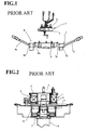
- A known steering shaft comprises a main shaft body, around which is provided a connector structure including a cable reel, combination switches, a cancel cam, a main scale, an encoder, and the like. As shown in Figs. 1 and 2, a
mobile body portion 5 of thecable reel 1 is fixed to the bottom end of a steering wheel via means forming a lobe (not shown in the figures). Afixed body portion 2 of thecable reel 1, to which themobile body portion 5 is fitted in a freely rotatable way, is then fitted on acombination switch body 3, the latter being in turn fixed to asteering column 4. One side of thecombination switch body 3 is provided with a turn-indicator unit (winker or blinker unit) 7, which includes ahousing 7astoring circuit elements 7b such as a turn signal-indicator switch (winker or blinker switch), and aturn signal lever 7c. The other side of thecombination switch body 3 is provided with a lighting unit 8, which includes ahousing 8astoring circuit elements 8b such as a lighting switch, and alighting lever 8c. - A space is formed between the
combination switch body 3 and asteering shaft 9, located beneath thecable reel 1. Inside this space, thecancel cam 10 is fixed to thesteering shaft 9, whilst the encoder (steering angle sensor) 11 is fixed to thesteering column 4. - The
cable reel 1 is in the form of a hollow torus defined by thefixed body portion 2 and themobile body portion 5. Thecable reel 1 can thus contain aflat cable 6 stored in a spiral. One end of theflat cable 6 is bound to thefixed body portion 2, whilst the other end is bound to themobile body portion 5, so that the signals passing through the flat cable can be transmitted to outside. When the steering wheel is turned, themobile body portion 5 is rotated clockwise or counter-clockwise correspondingly, and theflat cable 6 is likewise wound or unwound in the cable reel. - According to the above conception known in the prior art, the connector device units constituting a connector structure are mounted one by one around the steering shaft along the vehicle's production line. As a result, these device units are prone to be mounted askew relative to their intended positions with respect to the main axis of the steering shaft. Likewise, because the connector device units such as a turn indicator unit 7, a lighting unit 8, a
cable reel 1, acancel cam 10 and anencoder 11, are mounted individually, they must be prepared as individual units prior to assembling. Each connector device unit thus requires an individual housing and fixing means (e.g. bolts) or the like. The number of required spare parts is thus augmented. - In the above-mentioned prior art, each connector device unit is stored in an independent housing, and the
cable reel 1 is mounted into thecombination switch body 3. Because of this construction, the dimensions of the connector structure are made greater and larger as a whole. As a result, its weight is also increased. Moreover, the connector device units are usually manufactured by different manufacturers. Accordingly, when the connector device units are being assembled, a certain degree of clearance must be provided between them, and an otherwise unnecessary space must be envisaged. The connector structure is thus made even larger. - In view of these problems, it is an object of the present invention to provide a connector structure in unitary modules, so that they can be mounted together on a production line and installed without misfitting with respect to their intended positions relative to the steering shaft axis. Another object is to reduce the number of necessary construction parts and assembly steps. Yet another object is to prevent the connector structure from scaling up and increasing weight by altering the relative position where the cable reel is mounted.
- To this end, there is provided a connector structure incorporating a cable reel and switch system means, the connector structure comprising a connector shell having an axis, adapted to be joined with a steering shaft having an axis, so that both axes can be joined.
- The connector shell comprises a cylindrical section, with two end portions, fitting around the steering shaft in a freely rotatable way. The connector shell further comprises a receptacle section including a shoulder portion enlarging from one end portion of the cylindrical section, a peripheral sidewall portion, and first and second parting strip portions symmetrically provided with respect to the axis of the connector shell, thereby forming, inside the receptacle section, a central zone between the first and second parting strip portions, a first peripheral zone between the peripheral sidewall portion of the receptacle section and the first parting strip portion, and a second peripheral zone between the peripheral sidewall portion of the receptacle section and the second parting strip portion.
- The cable reel is then fitted and fixed in the central zone of the receptacle section.
- The above switch system means comprise at least a turn-indicator system and a lighting system, respectively fitted and fixed in the first peripheral zone of the receptacle portion and the second peripheral zone thereof.
- Preferably, the cable reel comprises a mobile body portion including a top wall and an internal sidewall, and the top wall comprises a cancel cam integrally formed therewith.
- Preferably yet, the cable reel comprises a mobile body portion including a top wall and an internal sidewall with salient tags, the salient tags being fixed with a main scale, and the cable reel further comprises a fixed body portion including a bottom wall and an external sidewall. The latter defines a third peripheral zone together with the peripheral sidewall portion of the receptacle section in a zone biased from said first and second peripheral zones around the axis of the connector shell, and the third peripheral zone contains an encoder, such that the encoder can detect the steering angle of the main scale.
- Suitably, the connector structure further comprises a shell lid which includes a top wall with a center hole and an external sidewall. The center hole is adapted to be passed through with the main axis of a steering wheel in a freely rotatable way, and the top wall and the external sidewall cover the connector shell.
- Preferably, the shell lid can also serve as a steering column cover.
- As understood from above, the connector shell is constructed substantially concentrically with respect to the main axis of the steering shaft. As the cable reel, turn-indicator system and lighting system are contained in such a connector shell, they are prevented from being biased from the predetermined positions when they are mounted around the main axis of the steering shaft. Further, the bottom end of the cylindrical section comprises a flange portion which fixes to the steering column, so that the mounting site is limited to only one position. Accordingly, the mounting steps in the assembly line for automobiles can be reduced.
- As the turn-indicator and lighting systems are stored in the connector shell, they are not required to be protected in separate housings. Further, the functional parts for these systems are stored as a whole in the connector shell. This can thus obviate the need for a space normally required for the separate housings. In addition, the cable reel is inserted into the central zone between the first and second parting strip portions. Accordingly, the height and horizontal size of the integrated connector structure can be reduced, and the whole structure becomes more compact. Furthermore, combination switches such as a turn-indicator system or a lighting system are not required to be protected in separate housings. Functional parts can thus be easily modified in or added to the above systems.
- In the prior art connector structure, the connector device units, to be incorporated into the connector structure, are often supplied by different manufacturers. In such a case, a certain degree of clearance between different connector device units must be provided. In the inventive connector structure, such a clearance is no longer required, so that the corresponding space, otherwise necessary, can be eliminated. As a result, the connector structure can further be miniaturized.
- The top area of the mobile body portion of the cable reel, which is contained in the connector shell, is provided with a cancel cam, whilst the bottom area thereof is provided with a main scale. Further, an encoder is provided in the peripheral zone formed between the cable reel and the peripheral sidewall portion of the connector shell. The position of the main scale can then be detected by the encoder. Typically, the peripheral zone where the encoder is installed is arranged in a position perpendicular to the axis linking the peripheral zones where the turn-indicator system and the lighting systems are located respectively.
- The above and the other objects, features and advantages of the present invention will be made apparent from the following description of the preferred embodiments, given as non-limiting examples, with reference to the accompanying drawings, in which:
- Fig. 1 is an exploded side view of a connector structure known in the prior art;
- Fig.2 is a cross-sectional side view of the assembled connector structure of the prior art;
- Fig.3 is a cross-sectional side view of a connector structure according to the invention;
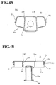
- Fig.4A is a schematic top plan view of a connector shell according to the present invention;
- Fig.4B is a schematic cross-sectional view of a connector shell according to the present invention;
- Fig.5A is an exploded top plan view of the connector structure according to the present invention;
- Fig.5B is an exploded side elevational view of the connector structure according to the present invention;
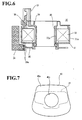
- Fig. 6 is a cross-sectional side view of a cable reel according to the invention; and
- Fig.7 is a top plan view of a shell lid, partly shown in phantom lines, according to the present invention,.
-
- Fig.3 shows a
connector structure 20 including aconnector shell 21 and incorporating acable reel 30 and combined switches. Theconnector shell 21 has a top opening, through which acable reel 30, a turn-indicator system 22, alighting system 23 and anencoder 24 and the like are mounted, and is covered with ashell lid 40. - The
connector shell 21 is made of a resin and formed into a shape shown in Figs.4A and 4B. This shape is configured so as to align with the axis L of asteering shaft 9. Theconnector shell 21 comprises acylindrical section 21a, into which thesteering shaft 9 fits in a freely rotatable way, and areceptacle section 21b enlarged from one end of thecylindrical section 21a in a direction perpendicular to the axis thereof. Thereceptacle section 21b comprises ashoulder portion 21c, aperipheral sidewall portion 21d, and first and secondparting strip portions cylindrical section 21a. - The first and second
parting strip portions hole 21g for locking thecable reel 30, and a system-lockinghole 21h for locking the corresponding turn-indicator system 22 or lighting system 23 (Fig.4B). The distal areas of theperipheral sidewall portion 21d, respectively adjacent the turn-indicator system 22 and thelighting system 23, comprise arespective notch 21i for passing a turn-indicator lever 25 or alighting lever 26. The same areas, but above the notches, include arespective locking claw 21j for locking the shell-lid 40. The other end of thecylindrical section 21a, opposed to thereceptacle section 21b, is provided with aflange portion 21k for fixing to a steering column. - Functional parts for the turn-indicator signal are grouped into a turn-
indicator system 22, the latter comprising a sidewall with afirst locking claw 22a. The turn-indicator system 22 is then inserted, as a unitary module, into the space between the firstparting strip portion 21e and theperipheral sidewall portion 21d. Thefirst locking claw 22a is inserted into, and locked with, the system-lockinghole 21h provided in the firstparting strip portion 21e. The above turn-indicator system 22 incorporates a printed circuit board on which are provided integral circuit elements including a turn-indicator switch. The turn-indicator lever 25 is linked to the turn-indicator system 22 by one of its ends, and the other end extending outwardly through thenotch 21i formed in theconnector shell 21. - Likewise, functional parts for the lighting are grouped into a
lighting system 23 which comprises a sidewall with asecond locking claw 23a. Thelighting system 23 is then inserted, as a unitary module, into the space between the secondparting strip portion 21f and theperipheral sidewall portion 21d. Thesecond locking claw 23a is inserted into, and locked with, the system-lockinghole 21h provided in the secondparting strip portion 21f. Theabove lighting system 23 incorporates a printed circuit board, on which are provided integral circuit elements including a lighting switch. Thelighting lever 26 is linked to thelighting system 23 by one of its ends, and the other end extending outwardly through thenotch 21i formed in theconnector shell 21. - As understood from above, the turn-
indicator system 22 and thelighting system 23, which are stored in individual housings in the prior art, are now contained directly in theconnector shell 21, without using separate housings. - As shown in Fig.5, the
cable reel 30 includes a cable enclosure defined by a fixedbody portion 31 and amobile body portion 32 e.g. a rotor. The fixedbody portion 31 includes an externalcircular sidewall 31a and a bottom wall, whilst themobile body portion 32 includes a top wall and an internal circular sidewall. The cable enclosure then contains aflat cable 33 in a spiraled state. The top wall of themobile body portion 32 then comprises a cancelcam 34 projecting upwardly therefrom, and aconnector portion 37 including aconductor 36 leading to theflat cable 33. The cancelcam 34 and theconnector portion 37 are formed integrally with themobile body portion 32. A cable terminal, connected to an inflator for an airbag, is inserted into theconnector portion 37, and connected to theconductor 36. - The external
circular sidewall 31a of the fixedbody portion 31, to which themobile body portion 32 is fitted in a freely rotatable way, carries first and second locking claws, respectively located at positions substantially opposed in a diametrical direction of thecable reel 30. When thecable reel 30 is fitted into theconnector shell 21, the first and second locking claws lock with the corresponding first andsecond locking holes 21g formed in the first and secondparting strip portions - The internal
circular sidewall 32a of themobile body portion 32 comprises bottom end sections or salient tags, where themain scale 35 are mounted. Further, theencoder 24 is mounted in a space formed between the externalcircular sidewall 31a of the fixedbody portion 31 and theperipheral sidewall portion 21d of theconnector shell 21. Theencoder 24 includes asensor portion 24a, by which the steering angle of themain scale 35 can be detected. - The
shell lid 40 comprises atop wall portion 40a covering the top opening of theconnector shell 21, and aperipheral sidewall portion 40b extending from thetop wall portion 40a down to near the base of thecylindrical section 21a of theconnector shell 21. Theshell lid 40 in the example is made of a resin. Thetop wall portion 40a is provided with acenter hole 40c, through which the main axis of the steering wheel is passed in a freely rotatable way, during assembly of the vehicle. Theperipheral sidewall portion 40b is provided with first andsecond notches 40d, through which switch levers 25 and 26 are extended . Two distal areas on theperipheral sidewall portion 40b, located above the respective first andsecond notches 40d (as viewed in Fig.3), are provided with arespective snap tag 40e for locking with acorresponding snap detent 21j formed on theperipheral sidewall portion 21d of theconnector shell 21. - The
shell lid 40 may also be configured so as to serve as a steering column cover known in the prior art. Alternatively, it may merely serve for closing the top opening of theconnector shell 21. - As mentioned above, the
inventive connector structure 20 comprises aconnector shell 21. Thisconnector shell 21 includes a peripheral sidewall portion, a first parting strip portion and a second parting strip portion, and has a top opening. Acable reel 30 is then mounted into theconnector shell 21 from the top opening thereof, so that thecable reel 30 is fitted into the central zone in theconnector shell 21, formed between the first and the secondparting strip portions signal system 22 and alighting system 23 are mounted into theconnector shell 21 from the top opening thereof, so that they are fitted into the peripheral zone of theconnector shell 21, formed between theperipheral sidewall portion 21d of theconnector shell 21 and one of the first and secondparting strip portions encoder 24 is fitted laterally onto thecable reel 30, prior to being fitted into theconnector shell 21, at a position circumferentially biased from the positions where the turn-indicator and lighting systems are mounted. - As the
connector structure 20 is now mounted with unitary modules, it can be assembled on a production line: thecylindrical section 21a of theconnector shell 21 is fitted around asteering shaft 9 by virtue of bearing means 60, and the bottom end (as viewed in Fig.3) of thesteering shaft 9 is fixed to a steering column. Subsequently, ashell lid 40 is placed such that the main axis of the steering wheel passes through thecenter hole 40c. Theshell lid 40 is fixed to themobile body portion 32 of thecable reel 30. - In the
above connector structure 20, acable reel 30, a turn-indicator system 22 and alighting system 23 are mounted into aconnector shell 21, prior to being fixed on asteering shaft 9. When thisconnector structure 20 is mounted onto asteering shaft 9, it suffices to join the central axis of theconnector shell 21 with that of thesteering shaft 9. By this simple action, the above unitary modules are placed precisely at a predetermined desired position, with respect to the axis of thesteering shaft 9. Further, as the assembly work is achieved by merely fixing theconnector shell 21 around the steering column, assembly steps are greatly simplified. - Further, the
cable reel 30 is placed on the same height level as the turn-signal system 22 and thelighting system 23, so that the height of the assembledconnector structure 20 is lowered. Moreover, the turn-signal system 22 and thelighting system 23 are not stored in separate housings, but contained in theconnector shell 21, so that the size and volume of the connector structure can be reduced, and the structure as a whole can be made more compact. - As can be understood from above, in the connector structure incorporating the cable reel and the combined switch systems according to the invention, the connector device units, respectively stored in a separate housing in the past, are stored in the sole connector shell, so obviating the need for corresponding separate housings, and the space necessary for mounting the device units is thus reduced. The clearance, otherwise necessary between the constitutive units, is also eliminated, so that the space can further be reduced.
- As functional parts for switching systems are no longer stored in separate housings, additions to, and modifications of, these functional parts can be carried out more easily. The connector structure thus has a wider use.
- Furthermore, all functional units are stored in the sole connector shell. Accordingly, when the central axis of the connector shell is joined with that of the steering shaft, those functional units are placed precisely at desired positions, with respect to the axis of the steering shaft.
Claims (5)
- A connector structure (20) incorporating a cable reel (30) and switch system means, said connector structure (20) comprising a connector shell (21) having an axis (L), adapted to be joined with a steering shaft (9) having an axis (L), so that both axes (L) can be joined, characterised in thatsaid connector shell (21) comprises a cylindrical section (21a) with two end portions and fitting around said steering shaft (9) in a freely rotatable way, said connector shell (21) further comprising a receptacle section (21b) including a shoulder portion (21c) enlarging from one end portion of said cylindrical section (21a), a peripheral sidewall portion (21d), and first and second parting strip portions (21e, 21f) symmetrically provided with respect to said axis (L) of said connector shell (21), thereby forming, inside said receptacle section (21b), a central zone between said first and second parting strip portions (21e, 21f), a first peripheral zone between said peripheral sidewall portion (21d) of said receptacle section (21b) and said first parting strip portion (21e), and a second peripheral zone between said peripheral sidewall portion (21d) of said receptacle section (21b) and said second parting strip portion (21f);said cable reel (30) being fitted and fixed in said central zone of said receptacle section (21b); andsaid switch system means comprising at least a turn-indicator system (22) and a lighting system (23), respectively fitted and fixed in said first peripheral zone of said receptacle portion (21b) and said second peripheral zone thereof.
- The connector structure (20) according to claim 1, wherein said cable reel (30) comprises a mobile body portion (32) including a top wall and an internal sidewall, and said top wall comprises a cancel cam (34) integrally formed therewith.
- The connector structure (20) according to claim 1 or 2, wherein said cable reel (30) comprises a mobile body portion (32) including a top wall and an internal sidewall (32a) with salient tags, said salient tags being fixed with a main scale (35), said cable reel (30) further comprises a fixed body portion (31) including a bottom wall and an external sidewall (31a), the latter defining a third peripheral zone together with said peripheral sidewall portion (21d) of said receptacle section (21b) in an area biased from said first and second peripheral zones around said axis of said connector shell (21), and said third peripheral zone contains an encoder (24), such that said encoder (24) can detect the steering angle of said main scale (35).
- The connector structure according to any one of claims 1 to 3, wherein said connector structure (20) further comprises a shell lid (40) which includes a top wall (40a) with a center hole (40c) and an external sidewall (40b), said center hole (40c) is adapted to be passed through with the main axis of a steering wheel in a freely rotatable way, and said top wall (40a) and said external sidewall (40b) cover said connector shell (21).
- The connector structure according to any one of claims 1 to 4, wherein said shell lid (40) can also serve as a steering column cover.
Applications Claiming Priority (2)
| Application Number | Priority Date | Filing Date | Title |
|---|---|---|---|
| JP2000114184 | 2000-04-14 | ||
| JP2000114184A JP2001294161A (en) | 2000-04-14 | 2000-04-14 | Assembly of cable reel and combination switch |
Publications (2)
| Publication Number | Publication Date |
|---|---|
| EP1145917A2 true EP1145917A2 (en) | 2001-10-17 |
| EP1145917A3 EP1145917A3 (en) | 2003-07-16 |
Family
ID=18626026
Family Applications (1)
| Application Number | Title | Priority Date | Filing Date |
|---|---|---|---|
| EP01400955A Withdrawn EP1145917A3 (en) | 2000-04-14 | 2001-04-12 | Connector structure incorporating a cable reel and combined switch systems |
Country Status (3)
| Country | Link |
|---|---|
| US (1) | US6500014B2 (en) |
| EP (1) | EP1145917A3 (en) |
| JP (1) | JP2001294161A (en) |
Families Citing this family (3)
| Publication number | Priority date | Publication date | Assignee | Title |
|---|---|---|---|---|
| KR100471893B1 (en) * | 2002-11-27 | 2005-03-09 | 현대자동차주식회사 | a steering column structure of vehicles |
| JP4582084B2 (en) * | 2006-12-05 | 2010-11-17 | 住友電装株式会社 | Seesaw switch |
| CN115891858B (en) * | 2023-01-19 | 2024-11-19 | 江铃汽车股份有限公司 | Combined switch shield mounting structure and vehicle |
Family Cites Families (10)
| Publication number | Priority date | Publication date | Assignee | Title |
|---|---|---|---|---|
| FR2718095B1 (en) * | 1994-03-31 | 1996-05-15 | Valeo Electronique | Support for switches for a steering column of a motor vehicle. |
| JPH0976826A (en) * | 1995-09-08 | 1997-03-25 | Niles Parts Co Ltd | Vehicle rotation connector screw fastening structure |
| JP3117632B2 (en) * | 1995-11-24 | 2000-12-18 | ナイルス部品株式会社 | Mounting structure of rotary connector and switch |
| JP3333387B2 (en) * | 1996-05-29 | 2002-10-15 | ナイルス部品株式会社 | Switch mounting structure |
| JPH1064647A (en) | 1996-08-26 | 1998-03-06 | Yazaki Corp | Connector with steering angle sensor and column structure using the same |
| US5773776A (en) * | 1996-10-21 | 1998-06-30 | Ut Automotive Dearborn, Inc. | Steering wheel assembly |
| JPH10241504A (en) * | 1997-02-24 | 1998-09-11 | Yazaki Corp | Signal transmission device for steering |
| JPH11191346A (en) * | 1997-12-26 | 1999-07-13 | Niles Parts Co Ltd | Column switch with rotary connector |
| JP3535970B2 (en) | 1998-04-13 | 2004-06-07 | 古河電気工業株式会社 | Column switch device |
| JP2001006493A (en) * | 1999-06-16 | 2001-01-12 | Sumitomo Wiring Syst Ltd | Mounting structure of cable reel and blinker / lighting switch to steering shaft |
-
2000
- 2000-04-14 JP JP2000114184A patent/JP2001294161A/en not_active Abandoned
-
2001
- 2001-04-10 US US09/828,959 patent/US6500014B2/en not_active Expired - Fee Related
- 2001-04-12 EP EP01400955A patent/EP1145917A3/en not_active Withdrawn
Non-Patent Citations (1)
| Title |
|---|
| None |
Also Published As
| Publication number | Publication date |
|---|---|
| EP1145917A3 (en) | 2003-07-16 |
| US6500014B2 (en) | 2002-12-31 |
| US20010030115A1 (en) | 2001-10-18 |
| JP2001294161A (en) | 2001-10-23 |
Similar Documents
| Publication | Publication Date | Title |
|---|---|---|
| US5936215A (en) | Steering roller connector signal transmission device on a steering wheel column | |
| US5607316A (en) | Structure for fixing a flat cable to a cylindrical rotator | |
| US6492744B1 (en) | Steering column switch for a motor vehicle | |
| US11325546B2 (en) | Rotary connector | |
| US7685906B2 (en) | Vehicle steering wheel | |
| US6583373B2 (en) | Steering column module | |
| EP0968883B1 (en) | Column switch | |
| EP1268242A1 (en) | Column electronics control assembly | |
| US20040102070A1 (en) | Steering column switch | |
| EP0861753B1 (en) | Combination switch | |
| EP1145915A2 (en) | Integrated connector device comprising a cable reel and combined switch systems | |
| US6500014B2 (en) | Connector structure incorporating a cable reel and combined switch systems | |
| US20020059838A1 (en) | Structure for mounting steering angle sensor for steering | |
| EP0926009B1 (en) | Column switch with rotary connector | |
| EP1149730B1 (en) | Swichting unit for steering wheel in motor vehicle | |
| JP5426259B2 (en) | Steering module | |
| US6770991B2 (en) | Roll connector structure for a vehicle | |
| JP3518662B2 (en) | Rotating connector | |
| EP0880205B1 (en) | Rotary connector mounting structure | |
| KR100298701B1 (en) | Combination switch device with rotary connector | |
| JP3424904B2 (en) | Steering device | |
| US20040174001A1 (en) | Generator carrier for a driver's gas bag module and function module for a steering wheel of a motor vehicle | |
| JPH09207787A (en) | Vehicle steering module | |
| EP1233887B1 (en) | Arrangement for a steering column |
Legal Events
| Date | Code | Title | Description |
|---|---|---|---|
| PUAI | Public reference made under article 153(3) epc to a published international application that has entered the european phase |
Free format text: ORIGINAL CODE: 0009012 |
|
| 17P | Request for examination filed |
Effective date: 20010420 |
|
| AK | Designated contracting states |
Kind code of ref document: A2 Designated state(s): AT BE CH CY DE DK ES FI FR GB GR IE IT LI LU MC NL PT SE TR |
|
| AX | Request for extension of the european patent |
Free format text: AL;LT;LV;MK;RO;SI |
|
| PUAL | Search report despatched |
Free format text: ORIGINAL CODE: 0009013 |
|
| AK | Designated contracting states |
Designated state(s): AT BE CH CY DE DK ES FI FR GB GR IE IT LI LU MC NL PT SE TR |
|
| AX | Request for extension of the european patent |
Extension state: AL LT LV MK RO SI |
|
| AKX | Designation fees paid |
Designated state(s): DE FR GB IT |
|
| STAA | Information on the status of an ep patent application or granted ep patent |
Free format text: STATUS: THE APPLICATION HAS BEEN WITHDRAWN |
|
| 17Q | First examination report despatched |
Effective date: 20040604 |
|
| 18W | Application withdrawn |
Effective date: 20040630 |