EP1145738A2 - Magnetic stimulation device with litz wire coil - Google Patents
Magnetic stimulation device with litz wire coil Download PDFInfo
- Publication number
- EP1145738A2 EP1145738A2 EP01109187A EP01109187A EP1145738A2 EP 1145738 A2 EP1145738 A2 EP 1145738A2 EP 01109187 A EP01109187 A EP 01109187A EP 01109187 A EP01109187 A EP 01109187A EP 1145738 A2 EP1145738 A2 EP 1145738A2
- Authority
- EP
- European Patent Office
- Prior art keywords
- coil
- treatment
- current
- magnetic
- biological body
- Prior art date
- Legal status (The legal status is an assumption and is not a legal conclusion. Google has not performed a legal analysis and makes no representation as to the accuracy of the status listed.)
- Granted
Links
Images



Classifications
-
- A—HUMAN NECESSITIES
- A61—MEDICAL OR VETERINARY SCIENCE; HYGIENE
- A61N—ELECTROTHERAPY; MAGNETOTHERAPY; RADIATION THERAPY; ULTRASOUND THERAPY
- A61N2/00—Magnetotherapy
- A61N2/02—Magnetotherapy using magnetic fields produced by coils, including single turn loops or electromagnets
-
- A—HUMAN NECESSITIES
- A61—MEDICAL OR VETERINARY SCIENCE; HYGIENE
- A61N—ELECTROTHERAPY; MAGNETOTHERAPY; RADIATION THERAPY; ULTRASOUND THERAPY
- A61N2/00—Magnetotherapy
- A61N2/004—Magnetotherapy specially adapted for a specific therapy
- A61N2/008—Magnetotherapy specially adapted for a specific therapy for pain treatment or analgesia
-
- H—ELECTRICITY
- H01—ELECTRIC ELEMENTS
- H01F—MAGNETS; INDUCTANCES; TRANSFORMERS; SELECTION OF MATERIALS FOR THEIR MAGNETIC PROPERTIES
- H01F7/00—Magnets
- H01F7/06—Electromagnets; Actuators including electromagnets
- H01F7/064—Circuit arrangements for actuating electromagnets
Definitions
- the present invention relates to a coil stimulator for a treatment magnetically stimulating the biological body by producing a time-varying magnetic field to induce eddy currents in the biological body by supplying pulse electric current to a litz wire coil.
- the present applicant has proposed a urinary incontinence treatment apparatus for magnetically stimulating biological body in JP-A-9-276418 (USP No.5,984,854) as filed previously, in place of the well-known electrical stimulator for treating urinary incontinence by applying a stimulating electrode to the patient and supplying electrical pulses.
- This apparatus has a magnetic stimulating coil mounted on a coil setter installed within the room, producing a pulse-like magnetic flux in its coil repetitively to extend the magnetic flux over the range from patient's waist to lower limbs and stimulating pelvic floor muscle group and pudendal nerve with eddy currents.
- the present applicant has proposed a magnetically stimulating coil for treatment of urinary incontinence in JP-A-10-234870, filed previously.
- the conventional coil employed a general electric wire or a copper pipe (hollow conductor). Therefore, the alternating current effective resistance of the conventional coil was so large as to cause significant electrical loss. Ultimately, the coil greatly generated heat during the use of device even by a few times, and the temperature of the coil was raised, leading to danger of burn. Thus, the conventional coil necessitated a cooling device with large capacity.
- an magnetic stimulator for stimulating nerve or muscle for treating nerve system by producing time-variable magnetic field to patient with muscle training
- the stimulator comprising a litz wire coil for producing magnetic filed to patient; and a power supply connected to the litz wire for providing time-variable electric current, wherein the electric variable current is controlled, such that alternate frequency of the current is set to be 1.0 ⁇ 3.3 kHz, the inductance of the coil is set to be 10 ⁇ 50 ⁇ H, pulse width of the current is 300 ⁇ s ⁇ 1 ms, peak value of the coil current is set to be 2500 ⁇ 8000A,stimulator frequency is 15 ⁇ 50 Hz.
- the nerve or muscle is selected from the group consisting of sacral nerves, the pelvic floor muscle group, or pudendal nerve for treatment of stress urinary incontinence or mixed urinary incontinece.
- a magnetic stimulator for magnetically stimulating biological body for treating nerve system by producing variable magnetic field to patient with muscle training or hyperthermia comprising:
- the biological body is the patella region of the patient for treatment of gonarthrosis.
- the biological body is the low back region of the patient for treatment of low back pain.
- the biological body is the ache region or pressure point for alleviate the ache of the patient for treatment of ache.
- the biological body is the shoulder or pressure points in shoulders to alleviate the stiffness of the patient for treatment of stiff neck.
- the biological body is the spasticity region for treatment of spasticity.
- the biological body is the carcinoma region for treatment of carcinoma.
- the biological body is the prostata for treatment of prostatic hyperplasia.
- the biological body is selected from the group consisting of waist, feromal region, leg, knee, ankle, or foot for treatment of difficult walking.
- the biological body is the bone or joint region for treatment of bone colitio acceleration or joint.
- a magnetic stimulator for magnetically stimulating biological body by producing variable magnetic field to patient for treatment with hyperthermia comprising:
- the biological body is the insufficient blood flow region for treatment of blood flow improvement.
- the biological body is the bone for treatment of bone colitio acceleration.
- a magnetic stimulator for magnetically stimulating biological body by producing variable magnetic field to patient comprising:
- the biological body is brain for treatment of parkinsonian syndrome or Parkinson's disease.
- the biological body is brain for transcranial brain diagnosis.
- the biological body is the pneumogastric nerve for treatment of epilepsy.
- the biological body is selected from the group consisting of sacral nerves, the pelvic floor muscle group, or pudendal nerve for treatment of urge urinary incontinence.
- the biological body is insufficient blood flow region for treatment of blood flow improvement.
- an magnetic stimulator for stimulating biological body by producing time-variable magnetic field to patient comprising:
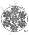
- FIG. 1 is a cross-sectional view of the litz wire coil 6.
- a bare wire 1 has a conductor portion 2 covered with an insulating layer 3.
- a first litz wire 4 consists of seven bare wires 1 twisted together and covered with an insulating layer 11 around its outside periphery.
- a second litz wire 5 consists of seven first litz wires 4 twisted together and covered with an insulating layer 12 around its outside periphery.
- a litz wire coil 6 consists of seven second litz wires 5 twisted together and covered with an insulating layer 13 around its outside periphery.
- the insulating layers 11, 12, 13 may be a glass fiber tape, a plastic tape or a rubber tape. Instead of the tapes, an insulating tube may be adopted, or a flexible adhesive of silicone may be used. The insulating layers 11 and 12 may be omitted.
- conductor has a skin effect by a high frequency electric current flow, so that the electric current is concentrated on the surface to increase effective resistance and electrical loss.
- the skin depth ⁇ is determined by the frequency of current in accordance with the following expression, and is reduced with larger frequency.
- ⁇ ⁇ 1/( ⁇ f ⁇ ) ⁇ 1/2
- ⁇ magnetic permeability
- o electric conductivity
- f frequency
- the effective resistance significantly increases when the radius of conductor is ⁇ or greater.
- the diameter of conductor portion 2 for the bare wire 1 in the litz wire coil 6 and the sectional area of litz wire coil 6 are determined by the size of space for winding the coil in accordance with the above relational expression.
- the bare wire 1 in the litz wire 6 shown in Fig. 1 may be made of soft copper wire, plated silver, plated thin or plated gold, Oxygen-free copper wire, or silver wire.
- Porous PTFE (Polyterafluoroethylene) or Blowing FEP (Fluorinated Ethylene Propylene) may preferably be applied for the insulated material of the insulated layer 3,11,12 13 in the litz wire 6.
- the insulated material may be multilayer which is constructed by winding Porous PTFE or Blowing FEP around the general insulated material such as PTFE, Porous PTFE, PFA, FEP, Blowing FEP, ETFE (Ethylene Tetrafluoroethylene), PVdF (Polyvinylidene), Milen film and Polymide film.
- the multilayer constructing by winding Porous PTFE ro Blowing FEP around or beneath the general jacket material such as polyethylene, nylon, vinyl chloride, or polyurethane.
- the insulating layer 3 of the bare wire 1 in the litz wire may be within 0.025 to 2.0mm thick
- the insulating layer 11 of the first litz wire 4 may be within 0.05 to 3mm thick
- the insulating layer 12 of the second litz wire 5 may be within 0.1 to 5mm thick
- the insulating layer 13 of the litz wire coil may be within 0.2 to 10 mm and may comprise acoustic insulation or noise absorbing material for reducing noise caused by contact between the turns of the coil.
- acoustic insulation or noise absorbing material for the particular bare wire or insulating layer may be omitted appropriately depending on the level of soundproofing effect.
- Diameter of the conductor portion 2 including bare wire 1 of the litz wire coil 6 is preferably 0.2 - 1.5 mm.
- the acoustic insulation or noise absorbing materials used for the insulating layers 3, 11, 12, 13 may include polyurethane foam, phenol foam, polyethylene foam, polystyrene foam, silicone, polysulfides, acrylics, denatured polysulfides, acrylic urethanes, butyl rubbers, SBRs, glass wools, rock fiber, felt, plastic sheet, and duck canvas.
- the property may be porous or perforated. A dry process is preferable to avoid danger of electric leakage.
- a first coil driving method for treatment of nerve system employing a coil portion having the litz wire coil 6 wound has such conditions that alternate frequency is 1.0 to 3.3kHz, inductance is 10 to 50 ⁇ H, pulse width is 300 ⁇ s to 1ms, peak value of coil current is 2500 to 8000A, and stimulation frequency is 15 to 50Hz.
- This first driving method is mainly intended for the treatment with muscle training effect, and particularly favorable for treatment of stress urinary incontinence and mixed urinary incontinence as the urinary incontinence treatment.
- the skin effect can be reduced by the use of litz wire so that heat generated from the coil portion can be significantly decreased, even if coil current with large peak value flows.
- a coil device is placed under the buttocks for stimulation so that magnetic flux is concentrated on pelvic floor muscle group, sacral nerve, or pudendal nerve.
- a second coil driving method for treatment of nerve system employing a coil portion having the litz wire coil 6 wound has such conditions that alternate frequency is 1.0 to 3.3kHz, inductance is 10 to 50 ⁇ H, pulse width is 300 ⁇ s to 1ms, peak value of coil current is 1000 to 5000A, and stimulation frequency is 50 to 100Hz.
- This second driving method is mainly intended for the treatment with muscle training effect or treatment with thermal effect, and may be favorable for treatment of gonarthrosis, low back pain, ache, stiff neck, spasticity, carcinoma, prostatic hyperplasia, difficulty walking, bone colitio acceleration, and joint.
- the muscle training may be conducted by burst magnetic stimulation to avoid muscle fatigue due to strong contraction.
- a coil device For treatment of gonarthrosis, a coil device is placed on or around patella closely and applies continuous or burst magnetic stimulation to remove or relieve pain.
- a coil device is placed around low backor waist proximately and applies continuous or burst magnetic stimulation to remove or relieve pain.
- a coil device is placed on aching region or effective pressure point to apply continuous or burst magnetic stimulation to relieve or alleviate the ache of the patient.
- the cause of ache is algesic substance produced as a result of stimulation or damage on the aching region .
- a coil device is placed on the shoulder proximately or pressure points effective in stiff neck in shouldersand applies magnetic stimulation to alleviate the stiffness of the patient.
- Spasticity is a state where stretch reflex has a low threshold and tendon reflex is accentuated so that clonus is prone to arise, and is typically caused by disturbance of pyramidal tract. Also, spasticity generally occurs with rigidity.
- the effect in suppressing on a spasticity region by magnetic stimulation can be explained on the basis of the reciprocal innervation theorem.
- the treatment condition is such that magnetic stimulation of 80 to 100Hz is applied to spasticity muscle for 15 to 30 minutes at a magnetic stimulation intensity to cause the maximum contraction for an antagonism period of spasticity muscle.
- the pulse width may be selected in a range from 100 ⁇ s to 1ms. Spasticity is alleviated by applying repetitive, continuous or burst magnetic stimulation to antagonist muscle of spasticity muscle.
- Spasticity walking has spasticity in the limb muscle or thigh adductor owing to disturbance of pyramidal tract.
- the magnetic material binding agent that is, an agent which peculiarly reacts against carcinoma tissue of the biological body that is bound with a magnetic material
- a continuous or burst magnetic stimulation is applied to carcinoma region.
- Carcinoma cell is so weak to the heat as to lose proliferation potential, and die out.
- carcinoma cell is typically weak to the heat, and if heated at temperatures from 42 to 45°C, particularly near 43°C, loses proliferation potential, and dies out soon. Thus, carcinoma cell is selectively heated and treated with possible least influence on the surrounding tissue.
- Carcinoma can be treated by applying a time-varying magnetic field to only the carcinoma tissue and heating the tissue.
- a conductive metal such as platinum, gold, silver or SUS is buried in the carcinoma tissue.
- the time-varying magnetic field is applied to the metal from outside the body. As a result, only the carcinoma tissue is heated and treatment of the carcinoma can be done.
- an ultrasonic heating method as a non-invasive tissue heating method without heating skin plane.
- the ultrasonic heating method can heat the carcinoma tissue deep in the body.
- the ultrasonic heating method is not suitable for the method of heating the position of the body which has plenty of gas, for example, lung, and not suitable for the method of heating the position which has bone near the position.
- prostatic hyperplasia causes for prostatic hyperplasia are aging and testicle. Due to these causes, hormone environment changes within the body are considered to cause prostatic hyperplasia.
- a coil device is placed on prostata to apply repetitive, continuous or burst magnetic stimulation to raise the temperature of hypertrophic part.
- Hyperthermia with temperatures of 45°C or below
- thermotherapy with temperatures of 45°C to 55°C or above.
- a coil device is placed on waist, femoral region, leg, knee, ankle or foot to apply repetitive, continuous or burst magnetic stimulation to ease or relieve difficulty walking.
- the treatment of bone colitio acceleration or joint is effective for comminuted fracture complicata, fracture owing to osteoporosis, intracervial fracture of femoral cervix, os scaphoideum fracture, infectiosis false jaw, and congenital pseudoarthrosis, and involves applying repetitive, continuous or burst magnetic stimulation to allow acceleration of bone colitio.
- a third coil driving method for treatment of nerve system employing a coil portion having the litz wire coil 6 wound has such conditions that alternate frequency is 1.0 to 3.3kHz, inductance is 10 to 50 ⁇ H, pulse width is 300 ⁇ s to 1ms, peak value of current is 1000 to 5000A, and stimulation frequency is 100Hz to 1MHz.
- This third driving method is mainly intended for the treatment with thermal effect, and may be favorable for blood flow improvement and bone colitio acceleration.
- stimulation with higher frequency leads to an increase in the number of current pulses per unit time passing through the biological body, and wider pulse width increases the time for which current flows through the biological body.
- current is consumed by impedance of the biological body to generate heat, giving rise to thermal effect due to generated heat.
- a coil device is placed on an insufficient blood flow region to apply repetitive, continuous or burst magnetic stimulation, to ameliorate circulation of the blood and make blood flow improvement.
- the factors of this thermal effect may include dermal vasodilation, blood inflow from the internal organs into the skin, acceleration of local metabolism, increased cardiac output or heart rate, fall in blood pressure, and stagnation of humor.
- a fourth coil driving method for treatment of nerve system employing a coil portion having the litz wire coil 6 wound has such conditions that alternate frequency is 3.3 to 10kHz, inductance is 10 to 50 ⁇ H, pulse width is 100 ⁇ s to 300 ⁇ s, peak value of current is 2500 to 8000A, and stimulation frequency is 1Hz to 10Hz.
- This fourth driving method is mainly intended for the treatment or diagnosis with nervous stimulation, and may be particularly favorable for treatment of parkinsonian syndrome or Parkinson's disease, diagnosis of transcranial brain stimulation, treatment of epilepsy, nerve amelioration, treatment of urge urinary incontinence, and blood flow improvement.
- This driving method involves small pulse width, and is appropriate for nervous stimulation.
- a coil device is placed proximately on the head to alleviate symptoms peculiar to parkinsonian syndrome or Parkinson's disease, or make walking movement nimble.
- Parkinsonian syndrome or Parkinson's disease occurs due to disorder of nigrostriate neuron which impedes secretion of dopamin that is nerve transmitter substance in striatum.
- a coil device with core for transcranial brain stimulation is provided. This coil device is placed in proximity of the head to apply repetitive, continuous or burst magnetic stimulation on a region to be stimulated within the brain without having undesirable influence on other region to be stimulated within the brain.
- a coil device For treatment of epilepsy, a coil device is placed in proximity of pneumogastric nerve to apply repetitive, continuous or burst magnetic stimulation to ease or relieve epileptic fit.
- magnetic stimulation is applied concentrically on pelvic floor muscle group, sacral nerve, or pudendal nerve.
- a coil device is placed on an insufficient blood flow region to apply repetitive, continuous or burst magnetic stimulation so that autonomic nerve is stimulated, blood flow circulation is improved, and blood flow is improved.
- the driving conditions for magnetic treatment or diagnosis are determined in accordance with various symptoms.
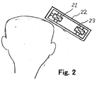
- Fig. 2 illustrates a coil device for treatment of nerve system that comprises a coil portion 21 having the litz wire coil of Fig. 1 wound and a housing 22.
- a gap is provided between the coil portion 21 and the housing 22.
- the coil portion 21 uses the litz wire coil to suppress generation of heat and has the gap 23 to prevent heat produced in the coil portion 21 from passing directly to the skin of biological body to cause burning at low temperatures. Since the peak value of density of eddy current developed owing to time-varying magnetic field generated by the coil portion 21 is located closer to the coil portion than the central axis, the coil device is placed near the stimulating region. Since the effective resistance can be reduced by suppressing the skin effect, large coil current can flow. As a result, magnetic stimulation with large stimulation intensity can be applied, there is no need of providing means for obtaining large eddy current by concentrating magnetic flux employing a core. In this way, no coil may be employed because of the use of litz wire.
- the coil device having the coil portion 21 is placed under buttock to concentrate a magnetic flux on pelvic floor muscle group, sacral nerve and pudendal nerve.
- the turns of litz wire coil 6 may be 5 to 100.
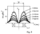
- Fig. 3 is a graph showing the distribution of eddy current density for numerical analysis when the coil portion 21 is used to stimulate the biological body 21.
- X axis is distance from the center of coil
- Y axis is absolute value of eddy current density
- Z is depth from the surface of biological body.
- the maximum value of eddy current density distribution occurs in normal direction of coil. Accordingly, the dimension of coil may be determined in accordance with the size of stimulating region.
- the diameter D of coil may be about 40mm to 160mm in view of broadening in pelvic floor muscle group, sacral nerve and pudendal nerve.
- a core may be used.
- Fig. 4 is an appearance of the essential part of a coil device with core.
- the core 8 is W type.
- the core 8 has two core elements 8a, 8b of U-character shape with one end directed upward and secured together.
- the core elements 8a, 8b are laminated or wound core, and may be preferably made of Permendul, grain oriented silicon steel strip, non-oriented silicon steel strip, Permalloy, Sendust, pure iron or ferrite.
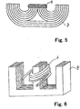
- the core 8 is W type, it may be a cut core as shown in Fig. 5. Instead of the W type core, the laminated core 8 may be E type as shown in Fig. 6.
- the coil portion may be installed under or in the seat, and seated as a chair.
- Fig. 7 shows the configuration of a driving unit for driving the litz wire coil 6.
- a capacitor 31 may be charged by an excitation power supply 32.
- the litz wire coil 6 is connected to the capacitor 31 via a circuit having a thyristor 33 and a diode 34 directed oppositely and connected in parallel.
- One end of the capacitor 31 is connected to a discharge portion 35.
- a control portion 36 controls the excitation power supply 32, the thyristor 33 and the discharge portion 35.
- An operation portion 37 is used to enter the data required for various instructions or controls into the control portion 36.
- the operation of the coil device thus constituted will be described below.
- a so-called maximal stimulation intensity method will be described below in which the stimulation intensity for the patient is gradually increased.
- the operator operates the operation portion 37 to gradually increase the voltage applied from the excitation power supply 32 to the capacitor 31 via the control portion 36.
- the control portion 36 controls such that current of one phase waveform flows through the litz wire coil 6 repetitively until the energy stored in the capacitor 31 reaches 40% of its maximal charge energy, and current of two phase waveform flows repetitively if it exceeds 40%.
- the operation portion 37 may be configured to choose a treatment object, so that the control portion 36 controls appropriately the above stimulation conditions for the chosen treatment object.
- a switch for selecting the treatment object to be stress, urge, or mixed may be provided in the operation portion 37, and the control portion 36 controls the chosen treatment object under the stimulation condition.
- each portion controls an electric power to be supplied from the excitation power supply 32 to the capacitor 31 and the capacitor 31 to be charged. Then, the control portion 36 sends a control pulse to the thyrister 33, and turns on the thyrister 33, so that current flows from the capacitor 31 via the thyrister 33 to the litz wire coil 6. Then, the control portion 36 controls the discharge portion 35 to discharge electric energy stored in the capacitor 31. Then, the control portion 36 turns off the thyrister 33. Thereafter, the above operation is repeated.
- each portion controls an electric power to be supplied from the excitation power supply 32 to the capacitor 31 and the capacitor 31 to be charged. Then, the control portion 36 sends a control pulse to the thyrister 33, and turns on the thyrister 33, so that current flows from the capacitor 31 via the thyrister 33 to the litz wire coil 6. And the capacitor 31 is charged again in reverse polarity. Then, the electric energy stored in the capacitor 31 is discharged to flow through the litz wire coil 6 and the diode 34. Then, the control portion 36 turns off the thyrister 33. Thereafter, the above operation is repeated.
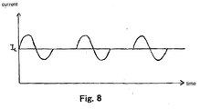
- Fig. 8 shows the waveform in the coil when output in two phase waveform by driving the coil.
- Fig. 9 shows how the electric field E varies at a certain point of the litz wire coil 6 in the case of two phase waveform.
- the period in the one phase waveform for which current flows through the litz wire coil 6 can be one-fourth or one-half the period T in the two phase waveform by controlling the timing of operation of the discharge portion 35 or the thyrister 33.
- the effective alternate resistance with the skin effect can be reduced and the power consumption efficiency and stimulation efficiency can be increased.
- the capacitance of capacitor can be made smaller and the device miniaturized. Since proximity effect can be suppressed, the coil diameter can be reduced while the effective resistance is not increased, and magnetic flux can be concentrated. Also, since the heat generation of coil can be decreased, burn of the patient can be avoided.
- a magnetic stimulator for magnetically stimulating biological body to make treatment or diagnosis by applying a time-varying magnetic field to nerve, muscle or disease part uses acoustic insulation or noise absorbing material for reducing noise caused by contact between wound coils parts.
Landscapes
- Health & Medical Sciences (AREA)
- Engineering & Computer Science (AREA)
- Public Health (AREA)
- Nuclear Medicine, Radiotherapy & Molecular Imaging (AREA)
- Radiology & Medical Imaging (AREA)
- Life Sciences & Earth Sciences (AREA)
- Animal Behavior & Ethology (AREA)
- General Health & Medical Sciences (AREA)
- Biomedical Technology (AREA)
- Veterinary Medicine (AREA)
- Electromagnetism (AREA)
- Physics & Mathematics (AREA)
- Hospice & Palliative Care (AREA)
- Medicinal Chemistry (AREA)
- Pain & Pain Management (AREA)
- Chemical & Material Sciences (AREA)
- Power Engineering (AREA)
- Magnetic Treatment Devices (AREA)
- Electrotherapy Devices (AREA)
Abstract
Description
- The present invention relates to a coil stimulator for a treatment magnetically stimulating the biological body by producing a time-varying magnetic field to induce eddy currents in the biological body by supplying pulse electric current to a litz wire coil.
- As an electrical treatment apparatus for treating urinary incontinence, the present applicant has proposed a urinary incontinence treatment apparatus for magnetically stimulating biological body in JP-A-9-276418 (USP No.5,984,854) as filed previously, in place of the well-known electrical stimulator for treating urinary incontinence by applying a stimulating electrode to the patient and supplying electrical pulses. This apparatus has a magnetic stimulating coil mounted on a coil setter installed within the room, producing a pulse-like magnetic flux in its coil repetitively to extend the magnetic flux over the range from patient's waist to lower limbs and stimulating pelvic floor muscle group and pudendal nerve with eddy currents. Also, the present applicant has proposed a magnetically stimulating coil for treatment of urinary incontinence in JP-A-10-234870, filed previously.
- Besides, various kinds of coil devices for magnetic treatment have been developed in recent years.
- However, the conventional coil employed a general electric wire or a copper pipe (hollow conductor). Therefore, the alternating current effective resistance of the conventional coil was so large as to cause significant electrical loss. Ultimately, the coil greatly generated heat during the use of device even by a few times, and the temperature of the coil was raised, leading to danger of burn. Thus, the conventional coil necessitated a cooling device with large capacity.
- It is an object of the invention to provide a practical magnetic treatment apparatus that is able to efficiently stimulate various magnetic treatment regions or diagnostic regions with a low consumption power.
- To achieve an object, according a first aspect of the present invention, there is provided an magnetic stimulator for stimulating nerve or muscle for treating nerve system by producing time-variable magnetic field to patient with muscle training, the stimulator comprising a litz wire coil for producing magnetic filed to patient; and a power supply connected to the litz wire for providing time-variable electric current, wherein the electric variable current is controlled, such that alternate frequency of the current is set to be 1.0~3.3 kHz, the inductance of the coil is set to be 10~50µH, pulse width of the current is 300 µs~1 ms, peak value of the coil current is set to be 2500~8000A,stimulator frequency is 15~50 Hz.
- According to the second aspect of the present invention, the nerve or muscle is selected from the group consisting of sacral nerves, the pelvic floor muscle group, or pudendal nerve for treatment of stress urinary incontinence or mixed urinary incontinece.
- According to the third aspect of the present invention, there is provided a magnetic stimulator for magnetically stimulating biological body for treating nerve system by producing variable magnetic field to patient with muscle training or hyperthermia comprising:
- a litz wire coil for producing magnetic filed to patient a power supply, supplying electric variable current to the litz wire coil, for producing magnetic filed to patient,the power supply connected to the litz wire;
- wherein the electric variable current is controlled, such that the alternate frequency of the current is set to be 1.0~3.3 kHz, the inductance of the coil is set to be 10~50µH, pulse width of the current is set to be 300 µs~1 ms, peak value of the coil current is set to be 1000~5000A and stimulation frequency is set to be 50~100 Hz.
-
- According to a forth aspect of the present invention, the biological body is the patella region of the patient for treatment of gonarthrosis.
- According to a fifth aspect of the present invention, the biological body is the low back region of the patient for treatment of low back pain.
- According to a sixth aspect of the present invention, the biological body is the ache region or pressure point for alleviate the ache of the patient for treatment of ache.
- According to a seventh aspect of the present invention, the biological body is the shoulder or pressure points in shoulders to alleviate the stiffness of the patient for treatment of stiff neck.
- According to an eighth aspect of the present invention, the biological body is the spasticity region for treatment of spasticity.
- According to a ninth aspect of the present invention, the biological body is the carcinoma region for treatment of carcinoma.
- According to a tenth aspect of the present invention, the biological body is the prostata for treatment of prostatic hyperplasia.
- According to an eleventh aspect of the present invention, the biological body is selected from the group consisting of waist, feromal region, leg, knee, ankle, or foot for treatment of difficult walking.
- According to a twelfth aspect of the present invention, the biological body is the bone or joint region for treatment of bone colitio acceleration or joint.
- According to a thirteenth aspect of the present invention, there is provided a magnetic stimulator for magnetically stimulating biological body by producing variable magnetic field to patient for treatment with hyperthermia comprising:
- a litz wire coil for producing magnetic filed to patient; and
- a power supply, for supplying electric variable current to the litz wire coil for producing magnetic filed to patient, the power supply connected to the litz wire,
- wherein the electric variable current is controlled such that the alternate frequency of the current is set to be 1.0~3.3 kHz, the inductance of the coil is set to be 10∼50µH, pulse width of the current is 300 µs∼1 ms, peak value of the coil current is 1000 ~5000A, stimulation frequency is 100 Hz~1 MHz.
-
- According to a fourteenth aspect of the present invention, the biological body is the insufficient blood flow region for treatment of blood flow improvement.
- According to a fifteenth aspect of the present invention, the biological body is the bone for treatment of bone colitio acceleration.
- According tot a sixteenth aspect of the present invention, there is provided a magnetic stimulator for magnetically stimulating biological body by producing variable magnetic field to patient comprising:
- a litz wire coil for producing magnetic filed to patient; and
- a power supply, for supplying electric variable current to litz wire coil, for producing magnetic filed to patient the power supply connected to the litz wire,
- wherein the electric variable current is controlled such that the alternate frequency of the current is set to be 3.3~10 kHz, the inductance of the coil is set to be 10~50µH, pulse width of the current is 100 µs~300 µs, peak value of the coil current is 2500∼8000A,stimulation frequency is 1 Hz~10 Hz.
-
- According to the seventeenth aspect of the present invention, the biological body is brain for treatment of parkinsonian syndrome or Parkinson's disease.
- According to the eighteenth aspect of the present invention, the biological body is brain for transcranial brain diagnosis.
- According to the ninteenth aspect of the present invention, the biological body is the pneumogastric nerve for treatment of epilepsy.
- According to the twentieth aspect of the present invention, the biological body is selected from the group consisting of sacral nerves, the pelvic floor muscle group, or pudendal nerve for treatment of urge urinary incontinence.
- According to the twenty-first aspect of the present invention, the biological body is insufficient blood flow region for treatment of blood flow improvement.
- According to the twenty-second aspect of the present invention, there is provided an magnetic stimulator for stimulating biological body by producing time-variable magnetic field to patient, the stimulator comprising:
- a litz wire coil for producing magnetic filed to patient, wherein the litz wire coil containing acoustic insulation or noise absorbing material for reducing noise caused by contact between coil parts; and
- a power supply connected to the litz wire for supplying electric variable current.
-
-
- Fig. 1 is a view illustrating the cross section of a
litz wire coil 6 of a device. - Fig. 2 is a cross-sectional view illustrating an example of
a stimulation device using the
litz wire coil 6 as shown in Fig. 1. - Fig. 3 is a graph showing eddy current density distribution arising within the biological body due to magnetic stimulation produced from the coil.
- Fig. 4 is a view illustrating an example of a coil with core
using the
litz wire coil 6 as shown in Fig. 1. - Fig. 5 is a view illustrating another example of the coil
with core using the
litz wire coil 6 as shown in Fig. 1. - Fig. 6 is a view illustrating another example of the coil
with core using the
litz wire coil 6 as shown in Fig. 1. - Fig. 7 is a circuit diagram showing the configuration of a driving portion of a device for producing time-varying magnetic field.
- Fig. 8 is a graph showing two phase waveform output from the driving portion of the device as shown in Fig. 8.
- Fig. 9 is a graph showing electric field produced by the driving portion of the device as shown in Fig. 8.
-
- A litz wire coil for magnetic treatment of muscle or nerve system according to the present invention will be described below. Fig. 1 is a cross-sectional view of the
litz wire coil 6. A bare wire 1 has aconductor portion 2 covered with an insulating layer 3. Afirst litz wire 4 consists of seven bare wires 1 twisted together and covered with aninsulating layer 11 around its outside periphery. A second litz wire 5 consists of sevenfirst litz wires 4 twisted together and covered with aninsulating layer 12 around its outside periphery. Alitz wire coil 6 consists of seven second litz wires 5 twisted together and covered with aninsulating layer 13 around its outside periphery. Theinsulating layers insulating layers - Generally, conductor has a skin effect by a high frequency electric current flow, so that the electric current is concentrated on the surface to increase effective resistance and electrical loss. The skin depth δ is determined by the frequency of current in accordance with the following expression, and is reduced with larger frequency.
- The effective resistance significantly increases when the radius of conductor is δ or greater. And the diameter of
conductor portion 2 for the bare wire 1 in thelitz wire coil 6 and the sectional area oflitz wire coil 6 are determined by the size of space for winding the coil in accordance with the above relational expression. - The bare wire 1 in the
litz wire 6 shown in Fig. 1 may be made of soft copper wire, plated silver, plated thin or plated gold, Oxygen-free copper wire, or silver wire. Porous PTFE (Polyterafluoroethylene) or Blowing FEP (Fluorinated Ethylene Propylene) may preferably be applied for the insulated material of theinsulated layer litz wire 6. Alternatively, the insulated material may be multilayer which is constructed by winding Porous PTFE or Blowing FEP around the general insulated material such as PTFE, Porous PTFE, PFA, FEP, Blowing FEP, ETFE (Ethylene Tetrafluoroethylene), PVdF (Polyvinylidene), Milen film and Polymide film. The multilayer constructing by winding Porous PTFE ro Blowing FEP around or beneath the general jacket material such as polyethylene, nylon, vinyl chloride, or polyurethane. - When current is applied to the coil shown in Fig. 1 , electromagnetic induction force is generated between the turns of the
coil 6 . This causes noise between the turns of thecoil 6, because they are attached to one another. Therefore, in order to relieve or prevent the noise, the insulating layer 3 of the bare wire 1 in the litz wire may be within 0.025 to 2.0mm thick, the insulatinglayer 11 of thefirst litz wire 4 may be within 0.05 to 3mm thick, and the insulatinglayer 12 of the second litz wire 5 may be within 0.1 to 5mm thick. Moreover, the insulatinglayer 13 of the litz wire coil may be within 0.2 to 10 mm and may comprise acoustic insulation or noise absorbing material for reducing noise caused by contact between the turns of the coil. - The use of acoustic insulation or noise absorbing material for the particular bare wire or insulating layer may be omitted appropriately depending on the level of soundproofing effect.
- Diameter of the
conductor portion 2 including bare wire 1 of thelitz wire coil 6 is preferably 0.2 - 1.5 mm. - The acoustic insulation or noise absorbing materials used for the insulating
layers - A first coil driving method for treatment of nerve system employing a coil portion having the
litz wire coil 6 wound has such conditions that alternate frequency is 1.0 to 3.3kHz, inductance is 10 to 50µH, pulse width is 300µs to 1ms, peak value of coil current is 2500 to 8000A, and stimulation frequency is 15 to 50Hz. This first driving method is mainly intended for the treatment with muscle training effect, and particularly favorable for treatment of stress urinary incontinence and mixed urinary incontinence as the urinary incontinence treatment. - With this first driving method, the skin effect can be reduced by the use of litz wire so that heat generated from the coil portion can be significantly decreased, even if coil current with large peak value flows.
- For treatment of stress urinary incontinence and mixed urinary incontinence, a coil device is placed under the buttocks for stimulation so that magnetic flux is concentrated on pelvic floor muscle group, sacral nerve, or pudendal nerve.
- A second coil driving method for treatment of nerve system employing a coil portion having the
litz wire coil 6 wound has such conditions that alternate frequency is 1.0 to 3.3kHz, inductance is 10 to 50µH, pulse width is 300µs to 1ms, peak value of coil current is 1000 to 5000A, and stimulation frequency is 50 to 100Hz. This second driving method is mainly intended for the treatment with muscle training effect or treatment with thermal effect, and may be favorable for treatment of gonarthrosis, low back pain, ache, stiff neck, spasticity, carcinoma, prostatic hyperplasia, difficulty walking, bone colitio acceleration, and joint. - With this second driving method, strong contraction of muscle is more likely to arise with higher stimulation frequency, and muscle stimulation is stronger with wider pulse width in the above range of pulse width. Such stimulation with higher frequency leads to an increase in the number of current pulses per unit time flowing through the biological body, and wider pulse width increases the time for which current flows through the biological body. Hence, current is consumed by impedance of the biological body to generate heat, obtaining thermal effect due to the generated heat. The repeated contraction and relaxation of muscle can strengthen the muscle.
- The muscle training may be conducted by burst magnetic stimulation to avoid muscle fatigue due to strong contraction.
- For treatment of gonarthrosis, a coil device is placed on or around patella closely and applies continuous or burst magnetic stimulation to remove or relieve pain.
- For low back pain treatment, a coil device is placed around low backor waist proximately and applies continuous or burst magnetic stimulation to remove or relieve pain.
- There are various causes for low back pain, which are typically classified into orthopaedic surgery region and internal medicine region, or aging and bad attitude. There is the effect of promoting blood circulation, relieving myotonia, or easing the ache by applying magnetic stimulation.
- For ache treatment, a coil device is placed on aching region or effective pressure point to apply continuous or burst magnetic stimulation to relieve or alleviate the ache of the patient.
- It is said that the cause of ache is algesic substance produced as a result of stimulation or damage on the aching region . There is the effect in blood flow improvement by magnetic stimulation, leading to treatment.
- For treatment of stiff neck, a coil device is placed on the shoulder proximately or pressure points effective in stiff neck in shouldersand applies magnetic stimulation to alleviate the stiffness of the patient.
- Spasticity is a state where stretch reflex has a low threshold and tendon reflex is accentuated so that clonus is prone to arise, and is typically caused by disturbance of pyramidal tract. Also, spasticity generally occurs with rigidity.
- The effect in suppressing on a spasticity region by magnetic stimulation can be explained on the basis of the reciprocal innervation theorem. The treatment condition is such that magnetic stimulation of 80 to 100Hz is applied to spasticity muscle for 15 to 30 minutes at a magnetic stimulation intensity to cause the maximum contraction for an antagonism period of spasticity muscle. The pulse width may be selected in a range from 100µs to 1ms. Spasticity is alleviated by applying repetitive, continuous or burst magnetic stimulation to antagonist muscle of spasticity muscle.
- Spasticity walking has spasticity in the limb muscle or thigh adductor owing to disturbance of pyramidal tract.
- In the hyperthermia of carcinoma, the magnetic material binding agent, that is, an agent which peculiarly reacts against carcinoma tissue of the biological body that is bound with a magnetic material, is injected into the biological body, and a continuous or burst magnetic stimulation is applied to carcinoma region. Carcinoma cell is so weak to the heat as to lose proliferation potential, and die out.
- It is said that carcinoma cell is typically weak to the heat, and if heated at temperatures from 42 to 45°C, particularly near 43°C, loses proliferation potential, and dies out soon. Thus, carcinoma cell is selectively heated and treated with possible least influence on the surrounding tissue.
- Carcinoma can be treated by applying a time-varying magnetic field to only the carcinoma tissue and heating the tissue. In this treatment, a conductive metal such as platinum, gold, silver or SUS is buried in the carcinoma tissue.
- Next, the time-varying magnetic field is applied to the metal from outside the body. As a result, only the carcinoma tissue is heated and treatment of the carcinoma can be done.
- Presently, there is an ultrasonic heating method as a non-invasive tissue heating method without heating skin plane. The ultrasonic heating method can heat the carcinoma tissue deep in the body.
- But ultrasonic waves generate strong reflection or refraction in the boundary where the sound impedance is large, for example, at the boundary between air-containing parts of the body (such as the lungs) and soft tissues, or between bones and soft tissues. Therefore, the ultrasonic heating method is not suitable for the method of heating the position of the body which has plenty of gas, for example, lung, and not suitable for the method of heating the position which has bone near the position.
- It is said that the causes for prostatic hyperplasia are aging and testicle. Due to these causes, hormone environment changes within the body are considered to cause prostatic hyperplasia.
- For treatment of prostatic hyperplasia, a coil device is placed on prostata to apply repetitive, continuous or burst magnetic stimulation to raise the temperature of hypertrophic part.
- According to the treatment, there are Hyperthermia with temperatures of 45°C or below, and thermotherapy with temperatures of 45°C to 55°C or above.
- For difficulty walking treatment, a coil device is placed on waist, femoral region, leg, knee, ankle or foot to apply repetitive, continuous or burst magnetic stimulation to ease or relieve difficulty walking.
- The treatment of bone colitio acceleration or joint is effective for comminuted fracture complicata, fracture owing to osteoporosis, intracervial fracture of femoral cervix, os scaphoideum fracture, infectiosis false jaw, and congenital pseudoarthrosis, and involves applying repetitive, continuous or burst magnetic stimulation to allow acceleration of bone colitio.
- A third coil driving method for treatment of nerve system employing a coil portion having the
litz wire coil 6 wound has such conditions that alternate frequency is 1.0 to 3.3kHz, inductance is 10 to 50µH, pulse width is 300µs to 1ms, peak value of current is 1000 to 5000A, and stimulation frequency is 100Hz to 1MHz. This third driving method is mainly intended for the treatment with thermal effect, and may be favorable for blood flow improvement and bone colitio acceleration. - With this third driving method, stimulation with higher frequency leads to an increase in the number of current pulses per unit time passing through the biological body, and wider pulse width increases the time for which current flows through the biological body. Hence, current is consumed by impedance of the biological body to generate heat, giving rise to thermal effect due to generated heat.
- For blood flow improvement, a coil device is placed on an insufficient blood flow region to apply repetitive, continuous or burst magnetic stimulation, to ameliorate circulation of the blood and make blood flow improvement. The factors of this thermal effect may include dermal vasodilation, blood inflow from the internal organs into the skin, acceleration of local metabolism, increased cardiac output or heart rate, fall in blood pressure, and stagnation of humor.
- A fourth coil driving method for treatment of nerve system employing a coil portion having the
litz wire coil 6 wound has such conditions that alternate frequency is 3.3 to 10kHz, inductance is 10 to 50µH, pulse width is 100µs to 300µs, peak value of current is 2500 to 8000A, and stimulation frequency is 1Hz to 10Hz. - This fourth driving method is mainly intended for the treatment or diagnosis with nervous stimulation, and may be particularly favorable for treatment of parkinsonian syndrome or Parkinson's disease, diagnosis of transcranial brain stimulation, treatment of epilepsy, nerve amelioration, treatment of urge urinary incontinence, and blood flow improvement. This driving method involves small pulse width, and is appropriate for nervous stimulation.
- With this fourth driving method, though the alternate frequency is higher and the peak value of current is higher than in the first to third driving methods, the use of litz wire can reduce the skin effect, and decrease the heat generation in the coil portion.
- For treatment of parkinsonian syndrome or Parkinson's disease, a coil device is placed proximately on the head to alleviate symptoms peculiar to parkinsonian syndrome or Parkinson's disease, or make walking movement nimble.
- Parkinsonian syndrome or Parkinson's disease occurs due to disorder of nigrostriate neuron which impedes secretion of dopamin that is nerve transmitter substance in striatum.
- Its main cause is considered to be disorder of dopamine biosynthesis owing to reduction of tyrosine hydroxylase.
- A coil device with core for transcranial brain stimulation is provided. This coil device is placed in proximity of the head to apply repetitive, continuous or burst magnetic stimulation on a region to be stimulated within the brain without having undesirable influence on other region to be stimulated within the brain.
- For treatment of epilepsy, a coil device is placed in proximity of pneumogastric nerve to apply repetitive, continuous or burst magnetic stimulation to ease or relieve epileptic fit.
- For treatment of urge urinary incontinence, magnetic stimulation is applied concentrically on pelvic floor muscle group, sacral nerve, or pudendal nerve.
- For blood flow improvement, a coil device is placed on an insufficient blood flow region to apply repetitive, continuous or burst magnetic stimulation so that autonomic nerve is stimulated, blood flow circulation is improved, and blood flow is improved.
- As described above, the driving conditions for magnetic treatment or diagnosis are determined in accordance with various symptoms.
- Fig. 2 illustrates a coil device for treatment of nerve system that comprises a
coil portion 21 having the litz wire coil of Fig. 1 wound and ahousing 22. A gap is provided between thecoil portion 21 and thehousing 22. Thecoil portion 21 uses the litz wire coil to suppress generation of heat and has thegap 23 to prevent heat produced in thecoil portion 21 from passing directly to the skin of biological body to cause burning at low temperatures. Since the peak value of density of eddy current developed owing to time-varying magnetic field generated by thecoil portion 21 is located closer to the coil portion than the central axis, the coil device is placed near the stimulating region. Since the effective resistance can be reduced by suppressing the skin effect, large coil current can flow. As a result, magnetic stimulation with large stimulation intensity can be applied, there is no need of providing means for obtaining large eddy current by concentrating magnetic flux employing a core. In this way, no coil may be employed because of the use of litz wire. - For treatment of urinary incontinence, the coil device having the
coil portion 21 is placed under buttock to concentrate a magnetic flux on pelvic floor muscle group, sacral nerve and pudendal nerve. The turns oflitz wire coil 6 may be 5 to 100. - Fig. 3 is a graph showing the distribution of eddy current density for numerical analysis when the
coil portion 21 is used to stimulate thebiological body 21. X axis is distance from the center of coil, Y axis is absolute value of eddy current density, and Z is depth from the surface of biological body. As will be apparent from this graph, the maximum value of eddy current density distribution occurs in normal direction of coil. Accordingly, the dimension of coil may be determined in accordance with the size of stimulating region. In the case of treatment of urinary incontinence, the diameter D of coil may be about 40mm to 160mm in view of broadening in pelvic floor muscle group, sacral nerve and pudendal nerve. - As described above, in order to enhance the stimulation efficiency by concentrating the magnetic flux, a core may be used. Fig. 4 is an appearance of the essential part of a coil device with core. As shown in Fig. 4, the
core 8 is W type. Thecore 8 has two core elements 8a, 8b of U-character shape with one end directed upward and secured together. The core elements 8a, 8b are laminated or wound core, and may be preferably made of Permendul, grain oriented silicon steel strip, non-oriented silicon steel strip, Permalloy, Sendust, pure iron or ferrite. - Though the
core 8 is W type, it may be a cut core as shown in Fig. 5. Instead of the W type core, thelaminated core 8 may be E type as shown in Fig. 6. - In particular, when the
core 8 is used for treatment of urinary incontinence, the coil portion may be installed under or in the seat, and seated as a chair. - Fig. 7 shows the configuration of a driving unit for driving the
litz wire coil 6. Acapacitor 31 may be charged by anexcitation power supply 32. Thelitz wire coil 6 is connected to thecapacitor 31 via a circuit having athyristor 33 and adiode 34 directed oppositely and connected in parallel. One end of thecapacitor 31 is connected to a discharge portion 35. Acontrol portion 36 controls theexcitation power supply 32, thethyristor 33 and the discharge portion 35. Anoperation portion 37 is used to enter the data required for various instructions or controls into thecontrol portion 36. - The operation of the coil device thus constituted will be described below. In this example, a so-called maximal stimulation intensity method will be described below in which the stimulation intensity for the patient is gradually increased. In beginning the treatment, the operator operates the
operation portion 37 to gradually increase the voltage applied from theexcitation power supply 32 to thecapacitor 31 via thecontrol portion 36. Thecontrol portion 36 controls such that current of one phase waveform flows through thelitz wire coil 6 repetitively until the energy stored in thecapacitor 31reaches 40% of its maximal charge energy, and current of two phase waveform flows repetitively if it exceeds 40%. - Herein, if the coil device is for general purpose, the
operation portion 37 may be configured to choose a treatment object, so that thecontrol portion 36 controls appropriately the above stimulation conditions for the chosen treatment object. In the urinary incontinence treatment device, a switch for selecting the treatment object to be stress, urge, or mixed may be provided in theoperation portion 37, and thecontrol portion 36 controls the chosen treatment object under the stimulation condition. - In the case of one phase waveform, the operation of each portion is as follows. First of all, the
control portion 36 controls an electric power to be supplied from theexcitation power supply 32 to thecapacitor 31 and thecapacitor 31 to be charged. Then, thecontrol portion 36 sends a control pulse to thethyrister 33, and turns on thethyrister 33, so that current flows from thecapacitor 31 via thethyrister 33 to thelitz wire coil 6. Then, thecontrol portion 36 controls the discharge portion 35 to discharge electric energy stored in thecapacitor 31. Then, thecontrol portion 36 turns off thethyrister 33. Thereafter, the above operation is repeated. - In the case of two phase waveform, the operation of each portion is as follows. First of all, the
control portion 36 controls an electric power to be supplied from theexcitation power supply 32 to thecapacitor 31 and thecapacitor 31 to be charged. Then, thecontrol portion 36 sends a control pulse to thethyrister 33, and turns on thethyrister 33, so that current flows from thecapacitor 31 via thethyrister 33 to thelitz wire coil 6. And thecapacitor 31 is charged again in reverse polarity. Then, the electric energy stored in thecapacitor 31 is discharged to flow through thelitz wire coil 6 and thediode 34. Then, thecontrol portion 36 turns off thethyrister 33. Thereafter, the above operation is repeated. Fig. 8 shows the waveform in the coil when output in two phase waveform by driving the coil. - Fig. 9 shows how the electric field E varies at a certain point of the
litz wire coil 6 in the case of two phase waveform. The period in the one phase waveform for which current flows through thelitz wire coil 6 can be one-fourth or one-half the period T in the two phase waveform by controlling the timing of operation of the discharge portion 35 or thethyrister 33. - In this way, current flowing through the
litz wire coil 6 is made in one phase waveform at first, and then in two phase waveform to attain a predetermined stimulation intensity or more. Thereby, the patient is accustomed to stimulation during the period of one phase waveform, and can be treated without giving abruptly increasing stimulation. - With this invention, a magnetic stimulator for magnetically stimulating biological body to make treatment or diagnosis by generating a time-varying magnetic field to nerve, muscle or disease part, wherein alternate frequency, inductance, pulse width, peak value of coil current, and stimulation frequency are set appropriately for the disease part, and a litz wire coil is used to produce the time-varying magnetic field. Hence, the effective alternate resistance with the skin effect can be reduced and the power consumption efficiency and stimulation efficiency can be increased. Moreover, the capacitance of capacitor can be made smaller and the device miniaturized. Since proximity effect can be suppressed, the coil diameter can be reduced while the effective resistance is not increased, and magnetic flux can be concentrated. Also, since the heat generation of coil can be decreased, burn of the patient can be avoided.
- Also, with this invention, a magnetic stimulator for magnetically stimulating biological body to make treatment or diagnosis by applying a time-varying magnetic field to nerve, muscle or disease part, the litz wire coil for producing the time-varying magnetic field uses acoustic insulation or noise absorbing material for reducing noise caused by contact between wound coils parts.
Claims (22)
- An magnetic stimulator for stimulating nerve or muscle for treating nerve system by producing time-variable magnetic field to patient with muscle training, the stimulator comprising:a litz wire coil for producing magnetic filed to patient; anda power supply connected to said litz wire for providing time-variable electric current;wherein said electric variable current is controlled, such that alternate frequency of said current is set to be 1.0~3.3 kHz, the inductance of said coil is set to be 10~50µH, pulse width of said current is 300 µs~1 ms, peak value of said coil current is set to be 2500~8000A, stimulator frequency is 15~50 Hz.
- An magnetic stimulator according to claim 1, wherein said nerve or muscle is selected from the group consisting of sacral nerves, the pelvic floor muscle group, or pudendal nerve for treatment of stress urinary incontinence or mixed urinary incontinece.
- An magnetic stimulator for magnetically stimulating biological body for treating nerve system by producing variable magnetic field to patient with muscle training or hyperthermia comprising:a litz wire coil for producing magnetic filed to patienta power supply, supplying electric variable current to said litz wire coil, for producing magnetic filed to patient, said power supply connected to said litz wire;wherein said electric variable current is controlled, such that said alternate frequency of said current is set to be 1.0 ~3.3 kHz, the inductance of said coil is set to be 10~50µ H, pulse width of said current is set to be 300 µs~1 ms, peak value of said coil current is set to be 1000~5000A and stimulation frequency is set to be 50~100 Hz.
- The magnetic stimulator according to claim 3, wherein said biological body is the patella region of the patient for treatment of gonarthrosis.
- The magnetic stimulator according to claim 3, wherein said biological body is the low back region of the patient for treatment of low back pain.
- The magnetic stimulator according to claim 3, wherein said biological body is the ache region or pressure point for alleviate the ache of the patient for treatment of ache.
- The magnetic stimulator according to claim 3, wherein said biological body is the shoulder or pressure points in shoulders to alleviate the stiffness of the patient for treatment of stiff neck.
- The magnetic stimulator according to claim 3, wherein said biological body is the spasticity region for treatment of spasticity.
- The magnetic stimulator according to claim 3, wherein said biological body is the carcinoma region for treatment of carcinoma.
- The magnetic stimulator according to claim 3, wherein said biological body is the prostata for treatment of prostatic hyperplasia.
- The magnetic stimulator according to claim 3, wherein said biological body is selected from the group consisting of waist, feromal region, leg, knee, ankle, or foot for treatment of difficult walking.
- The magnetic stimulator according to claim 3, wherein said biological body is the bone or joint region for treatment of bone colitio acceleration or joint.
- A magnetic stimulator for magnetically stimulating biological body by producing variable magnetic field to patient for treatment with hyperthermia comprising:a litz wire coil for producing magnetic filed to patient; anda power supply, for supplying electric variable current to said litz wire coil for producing magnetic filed to patient, said power supply connected to said litz wire,wherein said electric variable current is controlled such that said alternate frequency of said current is set to be 1.0 ~3.3 kHz, the inductance of said coil is set to be 10~50µH, pulse width of said current is 300 µs~1 ms, peak value of said coil current is 1000~5000A, stimulation frequency is 100 Hz∼1 MHz.
- The magnetic stimulator according to claim 13, wherein said biological body is the insufficient blood flow region for treatment of blood flow improvement.
- The magnetic stimulator according to claim 13, wherein said biological body is the bone for treatment of bone colitio acceleration.
- A magnetic stimulator for magnetically stimulating biological body by producing variable magnetic field to patient comprising:a litz wire coil for producing magnetic filed to patient; anda power supply, for supplying electric variable current to litz wire coil, for producing magnetic filed to patient said power supply connected to said litz wire,wherein said electric variable current is controlled such that said alternate frequency of said current is set to be 3.3 ~10 kHz, the inductance of said coil is set to be 10~50µH, pulse width of said current is 100 µs~300 µs, peak value of said coil current is 2500~8000A,stimulation frequency is 1 Hz~10 Hz.
- The magnetic stimulator according to claim 16, wherein said biological body is brain for treatment of parkinsonian syndrome or Parkinson's disease.
- The magnetic stimulator according to claim 16, wherein said biological body is brain for transcranial brain diagnosis.
- The magnetic stimulator according to claim 16, wherein said biological body is the pneumogastric nerve for treatment of epilepsy.
- The magnetic stimulator according to claim 16, wherein said biological body is selected from the group consisting of sacral nerves, the pelvic floor muscle group, or pudendal nerve for treatment of urge urinary incontinence.
- The magnetic stimulator according to claim 16, wherein said biological body is insufficient blood flow region for treatment of blood flow improvement.
- An magnetic stimulator for stimulating biological body by producing time-variable magnetic field to patient, the stimulator comprising:a litz wire coil for producing magnetic filed to patient, wherein said litz wire coil containing acoustic insulation or noise absorbing material for reducing noise caused by contact between coil parts; anda power supply connected to said litz wire for supplying electric variable current.
Applications Claiming Priority (2)
| Application Number | Priority Date | Filing Date | Title |
|---|---|---|---|
| JP2000113957 | 2000-04-14 | ||
| JP2000113957A JP2001293098A (en) | 2000-04-14 | 2000-04-14 | Coil device and coil drive device |
Publications (3)
| Publication Number | Publication Date |
|---|---|
| EP1145738A2 true EP1145738A2 (en) | 2001-10-17 |
| EP1145738A3 EP1145738A3 (en) | 2002-01-02 |
| EP1145738B1 EP1145738B1 (en) | 2008-11-12 |
Family
ID=18625840
Family Applications (1)
| Application Number | Title | Priority Date | Filing Date |
|---|---|---|---|
| EP01109187A Expired - Lifetime EP1145738B1 (en) | 2000-04-14 | 2001-04-12 | Magnetic stimulation device with litz wire coil |
Country Status (4)
| Country | Link |
|---|---|
| US (1) | US20010031906A1 (en) |
| EP (1) | EP1145738B1 (en) |
| JP (1) | JP2001293098A (en) |
| DE (1) | DE60136508D1 (en) |
Cited By (13)
| Publication number | Priority date | Publication date | Assignee | Title |
|---|---|---|---|---|
| WO2003090863A1 (en) * | 2002-04-24 | 2003-11-06 | Mcubetechnology Co., Ltd. | A stimulation coil using magnetic mirror and use thereof |
| WO2008078242A2 (en) | 2006-12-20 | 2008-07-03 | Philips Intellectual Property & Standards Gmbh | Arrangement and method for influencing and/or detecting magnetic particles in a region of action |
| WO2008078257A2 (en) | 2006-12-20 | 2008-07-03 | Philips Intellectual Property & Standards Gmbh | Arrangement for influencing and/or detecting magnetic particles in a region of action and method of producing a disk shaped coil |
| WO2008078269A3 (en) * | 2006-12-20 | 2008-08-28 | Philips Intellectual Property | Arrangement and method for influencing and/or detecting magnetic particles in a region of action, coil arrangement |
| WO2008078262A3 (en) * | 2006-12-20 | 2008-08-28 | Philips Intellectual Property | Arrangement and method for influencing and/or detecting and/or locating magnetic particles in a region of action |
| WO2008078261A3 (en) * | 2006-12-20 | 2008-09-25 | Philips Intellectual Property | Arrangement and method for influencing and/or detecting magnetic particles in a region of action |
| WO2011045002A1 (en) * | 2009-10-12 | 2011-04-21 | Quanten-Medicine Ag | Device for magnetically stimulating body tissue |
| EP1912699A4 (en) * | 2005-07-27 | 2011-06-29 | Neuronetics Inc | MAGNETIC CORE USED IN MEDICAL ACTS |
| WO2015193505A3 (en) * | 2014-06-20 | 2016-02-25 | Goetz, Stefan | Device and method for low-noise magnetic neurostimulation |
| CN111013018A (en) * | 2018-10-09 | 2020-04-17 | 胜美达集团株式会社 | Magnetic field generator for biostimulation |
| US11170912B2 (en) * | 2017-11-15 | 2021-11-09 | Illinois Tool Works Inc. | Resilient air-cooled induction heating cables |
| EP3316962B1 (en) | 2015-07-01 | 2021-12-22 | BTL Healthcare Technologies a.s. | Magnetic stimulation devices for therapeutic treatments |
| DE102023122274A1 (en) * | 2023-08-21 | 2025-02-27 | Niki Reiner Gleim | Electromagnetic applicator system |
Families Citing this family (85)
| Publication number | Priority date | Publication date | Assignee | Title |
|---|---|---|---|---|
| EP1120131A3 (en) * | 2000-01-27 | 2001-10-10 | Nihon Kohden Corporation | Electromagnetic coil apparatus for urinary incontinence treatment |
| US20020097125A1 (en) * | 2000-06-05 | 2002-07-25 | Kent Davey | Method for optimizing transcranial magnetic stimulation cores and magnetic cores produced thereby |
| US7153256B2 (en) * | 2003-03-07 | 2006-12-26 | Neuronetics, Inc. | Reducing discomfort caused by electrical stimulation |
| US8118722B2 (en) | 2003-03-07 | 2012-02-21 | Neuronetics, Inc. | Reducing discomfort caused by electrical stimulation |
| US10350428B2 (en) | 2014-11-04 | 2019-07-16 | Endonovo Therapetics, Inc. | Method and apparatus for electromagnetic treatment of living systems |
| US9433797B2 (en) | 2003-12-05 | 2016-09-06 | Rio Grande Neurosciences, Inc. | Apparatus and method for electromagnetic treatment of neurodegenerative conditions |
| US9427598B2 (en) | 2010-10-01 | 2016-08-30 | Rio Grande Neurosciences, Inc. | Method and apparatus for electromagnetic treatment of head, cerebral and neural injury in animals and humans |
| US9656096B2 (en) | 2003-12-05 | 2017-05-23 | Rio Grande Neurosciences, Inc. | Method and apparatus for electromagnetic enhancement of biochemical signaling pathways for therapeutics and prophylaxis in plants, animals and humans |
| US9415233B2 (en) | 2003-12-05 | 2016-08-16 | Rio Grande Neurosciences, Inc. | Apparatus and method for electromagnetic treatment of neurological pain |
| US8961385B2 (en) | 2003-12-05 | 2015-02-24 | Ivivi Health Sciences, Llc | Devices and method for treatment of degenerative joint diseases with electromagnetic fields |
| US9440089B2 (en) | 2003-12-05 | 2016-09-13 | Rio Grande Neurosciences, Inc. | Apparatus and method for electromagnetic treatment of neurological injury or condition caused by a stroke |
| NZ551316A (en) | 2004-04-19 | 2008-03-28 | Ivivi Technologies Inc | Electromagnetic treatment apparatus and method |
| JPWO2005104622A1 (en) * | 2004-04-23 | 2008-03-13 | 独立行政法人科学技術振興機構 | Coil device and magnetic field generator |
| US7601115B2 (en) * | 2004-05-24 | 2009-10-13 | Neuronetics, Inc. | Seizure therapy method and apparatus |
| US7857746B2 (en) * | 2004-10-29 | 2010-12-28 | Nueronetics, Inc. | System and method to reduce discomfort using nerve stimulation |
| US7396326B2 (en) * | 2005-05-17 | 2008-07-08 | Neuronetics, Inc. | Ferrofluidic cooling and acoustical noise reduction in magnetic stimulators |
| US7976451B2 (en) * | 2005-06-16 | 2011-07-12 | The United States Of America As Represented By The Department Of Health And Human Services | Transcranial magnetic stimulation system and methods |
| WO2007112578A1 (en) * | 2006-04-04 | 2007-10-11 | University Health Network | A coil electrode apparatus for thermal therapy |
| JP5530182B2 (en) * | 2006-12-20 | 2014-06-25 | コーニンクレッカ フィリップス エヌ ヴェ | Method and apparatus for influencing and / or detecting magnetic particles in a working region |
| US8128549B2 (en) * | 2007-02-20 | 2012-03-06 | Neuronetics, Inc. | Capacitor failure detection |
| US20080243197A1 (en) * | 2007-04-02 | 2008-10-02 | Thomas Bove | Therapeutic applicator system for applying light, sound and/or magnetism |
| US7744523B2 (en) * | 2007-06-07 | 2010-06-29 | Emory University | Drive circuit for magnetic stimulation |
| US20090108969A1 (en) * | 2007-10-31 | 2009-04-30 | Los Alamos National Security | Apparatus and method for transcranial and nerve magnetic stimulation |
| US9272157B2 (en) | 2010-05-02 | 2016-03-01 | Nervive, Inc. | Modulating function of neural structures near the ear |
| WO2011139851A1 (en) | 2010-05-02 | 2011-11-10 | Lake Biosciences, Llc | Modulating function of the facial nerve system or related neural structures via the ear |
| US9943360B2 (en) | 2011-01-30 | 2018-04-17 | University Health Network | Coil electrode for thermal therapy |
| DE102011014291A1 (en) * | 2011-03-17 | 2012-09-20 | Magic Race Llc | Device for extracorporeal magnetic innervation |
| US8343027B1 (en) | 2012-01-30 | 2013-01-01 | Ivivi Health Sciences, Llc | Methods and devices for providing electromagnetic treatment in the presence of a metal-containing implant |
| DE102012013534B3 (en) | 2012-07-05 | 2013-09-19 | Tobias Sokolowski | Apparatus for repetitive nerve stimulation for the degradation of adipose tissue by means of inductive magnetic fields |
| JP6189439B2 (en) | 2012-07-30 | 2017-08-30 | ニューロプレックス インコーポレイテッド | Apparatus and method for magnetic stimulation for the treatment of neurological disorders |
| KR101447532B1 (en) | 2012-09-14 | 2014-10-10 | 주식회사 리메드 | Stimulus treatment using magnetic field |
| US10065047B2 (en) | 2013-05-20 | 2018-09-04 | Nervive, Inc. | Coordinating emergency treatment of cardiac dysfunction and non-cardiac neural dysfunction |
| US9849301B2 (en) * | 2014-01-15 | 2017-12-26 | Neuronetics, Inc. | Magnetic stimulation coils and ferromagnetic components for reduced surface stimulation and improved treatment depth |
| EP3131628A4 (en) | 2014-04-16 | 2017-11-22 | Ivivi Health Sciences, LLC | A two-part pulsed electromagnetic field applicator for application of therapeutic energy |
| GB2530475A (en) * | 2014-06-20 | 2016-03-30 | Stefan M Goetz | Device and method for quiet magnetic neurostimulation |
| US11491342B2 (en) | 2015-07-01 | 2022-11-08 | Btl Medical Solutions A.S. | Magnetic stimulation methods and devices for therapeutic treatments |
| US10124187B2 (en) * | 2015-04-28 | 2018-11-13 | Btl Holdings Limited | Combination of radiofrequency and magnetic treatment methods |
| US9919161B2 (en) | 2015-07-01 | 2018-03-20 | Btl Holdings Limited | Method of neural structure stimulation by magnetic field |
| US9636519B2 (en) | 2015-07-01 | 2017-05-02 | Btl Holdings Limited | Magnetic stimulation methods and devices for therapeutic treatments |
| US10478634B2 (en) | 2015-07-01 | 2019-11-19 | Btl Medical Technologies S.R.O. | Aesthetic method of biological structure treatment by magnetic field |
| US20180001107A1 (en) | 2016-07-01 | 2018-01-04 | Btl Holdings Limited | Aesthetic method of biological structure treatment by magnetic field |
| US10709894B2 (en) | 2015-07-01 | 2020-07-14 | Btl Medical Technologies S.R.O. | Aesthetic method of biological structure treatment by magnetic field |
| US10569095B1 (en) | 2015-07-01 | 2020-02-25 | Btl Medical Technologies S.R.O. | Aesthetic method of biological structure treatment by magnetic field |
| US9937358B2 (en) | 2015-07-01 | 2018-04-10 | Btl Holdings Limited | Aesthetic methods of biological structure treatment by magnetic field |
| US9974519B1 (en) | 2015-07-01 | 2018-05-22 | Btl Holdings Limited | Aesthetic method of biologoical structure treatment by magnetic field |
| US10549109B2 (en) | 2015-07-01 | 2020-02-04 | Btl Medical Technologies S.R.O. | Aesthetic method of biological structure treatment by magnetic field |
| US10695576B2 (en) | 2015-07-01 | 2020-06-30 | Btl Medical Technologies S.R.O. | Aesthetic method of biological structure treatment by magnetic field |
| US10471269B1 (en) | 2015-07-01 | 2019-11-12 | Btl Medical Technologies S.R.O. | Aesthetic method of biological structure treatment by magnetic field |
| US10821295B1 (en) | 2015-07-01 | 2020-11-03 | Btl Medical Technologies S.R.O. | Aesthetic method of biological structure treatment by magnetic field |
| US10549110B1 (en) | 2015-07-01 | 2020-02-04 | Btl Medical Technologies S.R.O. | Aesthetic method of biological structure treatment by magnetic field |
| US11266850B2 (en) | 2015-07-01 | 2022-03-08 | Btl Healthcare Technologies A.S. | High power time varying magnetic field therapy |
| US10569094B2 (en) | 2015-07-01 | 2020-02-25 | Btl Medical Technologies S.R.O. | Aesthetic method of biological structure treatment by magnetic field |
| US10478633B2 (en) | 2015-07-01 | 2019-11-19 | Btl Medical Technologies S.R.O. | Aesthetic method of biological structure treatment by magnetic field |
| US10695575B1 (en) | 2016-05-10 | 2020-06-30 | Btl Medical Technologies S.R.O. | Aesthetic method of biological structure treatment by magnetic field |
| US10493293B2 (en) | 2015-07-01 | 2019-12-03 | Btl Medical Technologies S.R.O. | Aesthetic method of biological structure treatment by magnetic field |
| US10245439B1 (en) | 2015-07-01 | 2019-04-02 | Medical Technologies Cz A.S. | Aesthetic method of biological structure treatment by magnetic field |
| US11253717B2 (en) | 2015-10-29 | 2022-02-22 | Btl Healthcare Technologies A.S. | Aesthetic method of biological structure treatment by magnetic field |
| US10195034B2 (en) * | 2015-11-20 | 2019-02-05 | Board Of Trustees Of Southern Illinois University | Systems and methods for magnetic induction of a penile prosthesis |
| IL243686B (en) | 2016-01-19 | 2022-05-01 | Epitech Mag Ltd | Device for enhancing ocular epithelial integrity via magnetic pulses |
| US11247039B2 (en) | 2016-05-03 | 2022-02-15 | Btl Healthcare Technologies A.S. | Device including RF source of energy and vacuum system |
| US11464993B2 (en) | 2016-05-03 | 2022-10-11 | Btl Healthcare Technologies A.S. | Device including RF source of energy and vacuum system |
| US10709895B2 (en) | 2016-05-10 | 2020-07-14 | Btl Medical Technologies S.R.O. | Aesthetic method of biological structure treatment by magnetic field |
| US11534619B2 (en) | 2016-05-10 | 2022-12-27 | Btl Medical Solutions A.S. | Aesthetic method of biological structure treatment by magnetic field |
| US10583287B2 (en) | 2016-05-23 | 2020-03-10 | Btl Medical Technologies S.R.O. | Systems and methods for tissue treatment |
| US10556122B1 (en) | 2016-07-01 | 2020-02-11 | Btl Medical Technologies S.R.O. | Aesthetic method of biological structure treatment by magnetic field |
| US11141219B1 (en) | 2016-08-16 | 2021-10-12 | BTL Healthcare Technologies, a.s. | Self-operating belt |
| WO2018089795A1 (en) | 2016-11-10 | 2018-05-17 | Qoravita LLC | System and method for applying a low frequency magnetic field to biological tissues |
| US11896823B2 (en) | 2017-04-04 | 2024-02-13 | Btl Healthcare Technologies A.S. | Method and device for pelvic floor tissue treatment |
| US10039929B1 (en) | 2017-04-04 | 2018-08-07 | BLT Holdings Limited | Method and device for pelvic floor tissue treatment |
| IL253677B2 (en) * | 2017-07-26 | 2023-06-01 | Epitech Mag Ltd | Magnetic device for treating living tissues |
| US11000693B2 (en) | 2018-02-20 | 2021-05-11 | Neuronetics, Inc. | Magnetic stimulation coils and ferromagnetic components for treatment and diagnostic procedures |
| BR102019004205A2 (en) * | 2019-02-28 | 2020-10-06 | Mario Fernandes Chammas Junior | DEVICE FOR TREATING PROSTATIC INCREASE THROUGH THE USE OF PULSED ELECTROMAGNETIC FIELD |
| PL4417249T3 (en) | 2019-04-11 | 2026-04-20 | Btl Medical Solutions A.S. | Devices for treatment of biological structures by radiofrequency |
| US12156689B2 (en) | 2019-04-11 | 2024-12-03 | Btl Medical Solutions A.S. | Methods and devices for aesthetic treatment of biological structures by radiofrequency and magnetic energy |
| US12558146B2 (en) | 2019-04-11 | 2026-02-24 | Btl Medical Solutions A.S. | Methods and devices for aesthetic treatment of biological structures by radiofrequency and magnetic energy |
| US12611545B2 (en) | 2020-05-04 | 2026-04-28 | Btl Healthcare Technologies A.S. | Device and method for unattended treatment of a patient |
| ES2993637T3 (en) | 2020-05-04 | 2025-01-03 | Btl Healthcare Technologies As | Device for unattended treatment of a patient |
| US11878167B2 (en) | 2020-05-04 | 2024-01-23 | Btl Healthcare Technologies A.S. | Device and method for unattended treatment of a patient |
| US20220080217A1 (en) * | 2020-09-16 | 2022-03-17 | Duke University | Methods and systems for magnetic stimulation |
| JP7650056B2 (en) * | 2021-03-04 | 2025-03-24 | 株式会社Ifg | Magnetic Stimulation Device |
| US11147982B1 (en) * | 2021-05-05 | 2021-10-19 | Kambix Innovations, Llc | Method and system for thermal stimulation of targeted neural circuits for neurodegenerative disorders |
| CA3260012A1 (en) | 2021-10-13 | 2023-04-20 | Btl Medical Solutions A.S. | Devices for aesthetic treatment of biological structures by radiofrequency and magnetic energy |
| US11896816B2 (en) | 2021-11-03 | 2024-02-13 | Btl Healthcare Technologies A.S. | Device and method for unattended treatment of a patient |
| KR20260021730A (en) * | 2023-06-13 | 2026-02-13 | 소노스틱스, 아이엔씨. | Devices, systems and methods using magnetic neuromodulation for treating decreased cardiac output in humans, and methods related thereto |
| US20260097227A1 (en) | 2024-10-08 | 2026-04-09 | Btl Medical Solutions A.S. | Devices and methods for application of a magnetic field to the nervous system |
Citations (2)
| Publication number | Priority date | Publication date | Assignee | Title |
|---|---|---|---|---|
| JPH10234870A (en) | 1996-12-27 | 1998-09-08 | Nippon Koden Corp | Magnetic stimulation type incontinence treatment coil device |
| US5984854A (en) | 1996-02-15 | 1999-11-16 | Nihon Kohden Corporation | Method for treating urinary incontinence and an apparatus therefor |
Family Cites Families (7)
| Publication number | Priority date | Publication date | Assignee | Title |
|---|---|---|---|---|
| GB2111316B (en) * | 1981-12-11 | 1985-04-17 | Westinghouse Electric Corp | An unjointed amorphous metal core for an electrical induction apparatus |
| US4545368A (en) * | 1983-04-13 | 1985-10-08 | Rand Robert W | Induction heating method for use in causing necrosis of neoplasm |
| US5116304A (en) * | 1987-01-28 | 1992-05-26 | Cadwell Industries, Inc. | Magnetic stimulator with skullcap-shaped coil |
| US6086525A (en) * | 1994-11-28 | 2000-07-11 | Neotonus, Inc. | Magnetic nerve stimulator for exciting peripheral nerves |
| JP3086387B2 (en) * | 1994-12-14 | 2000-09-11 | 川崎製鉄株式会社 | Non-oriented electrical steel sheet for transformers with small leakage flux |
| JPH09276418A (en) * | 1996-02-15 | 1997-10-28 | Nippon Koden Corp | Urinary incontinence treatment device |
| US6266556B1 (en) * | 1998-04-27 | 2001-07-24 | Beth Israel Deaconess Medical Center, Inc. | Method and apparatus for recording an electroencephalogram during transcranial magnetic stimulation |
-
2000
- 2000-04-14 JP JP2000113957A patent/JP2001293098A/en active Pending
-
2001
- 2001-04-12 DE DE60136508T patent/DE60136508D1/en not_active Expired - Lifetime
- 2001-04-12 EP EP01109187A patent/EP1145738B1/en not_active Expired - Lifetime
- 2001-04-13 US US09/833,686 patent/US20010031906A1/en not_active Abandoned
Patent Citations (2)
| Publication number | Priority date | Publication date | Assignee | Title |
|---|---|---|---|---|
| US5984854A (en) | 1996-02-15 | 1999-11-16 | Nihon Kohden Corporation | Method for treating urinary incontinence and an apparatus therefor |
| JPH10234870A (en) | 1996-12-27 | 1998-09-08 | Nippon Koden Corp | Magnetic stimulation type incontinence treatment coil device |
Cited By (29)
| Publication number | Priority date | Publication date | Assignee | Title |
|---|---|---|---|---|
| WO2003090863A1 (en) * | 2002-04-24 | 2003-11-06 | Mcubetechnology Co., Ltd. | A stimulation coil using magnetic mirror and use thereof |
| EP1912699A4 (en) * | 2005-07-27 | 2011-06-29 | Neuronetics Inc | MAGNETIC CORE USED IN MEDICAL ACTS |
| US10617884B2 (en) | 2005-07-27 | 2020-04-14 | Neurontics, Inc. | Magnetic core for medical procedures |
| EP3332837A1 (en) * | 2005-07-27 | 2018-06-13 | Neuronetics, Inc. | Magnetic core for medical procedures |
| US9931518B2 (en) | 2005-07-27 | 2018-04-03 | Neuronetics, Inc. | Magnetic core for medical procedures |
| US9308386B2 (en) | 2005-07-27 | 2016-04-12 | Neuronetics, Inc. | Magnetic core for medical procedures |
| US8657731B2 (en) | 2005-07-27 | 2014-02-25 | Neuronetics, Inc. | Magnetic core for medical procedures |
| US8246529B2 (en) | 2005-07-27 | 2012-08-21 | Neuronetics, Inc. | Magnetic core for medical procedures |
| WO2008078257A3 (en) * | 2006-12-20 | 2008-11-27 | Philips Intellectual Property | Arrangement for influencing and/or detecting magnetic particles in a region of action and method of producing a disk shaped coil |
| WO2008078262A3 (en) * | 2006-12-20 | 2008-08-28 | Philips Intellectual Property | Arrangement and method for influencing and/or detecting and/or locating magnetic particles in a region of action |
| US8183860B2 (en) | 2006-12-20 | 2012-05-22 | Koninklijke Philips Electronics N.V. | Arrangement and method for influencing and/or detecting magnetic particles in a region of action |
| US8188732B2 (en) | 2006-12-20 | 2012-05-29 | Koninklijke Philips Electronics N.V. | Arrangement and method for influencing magnetic particles in a region of action using distinguishable magnetization of the two magnetic particles |
| WO2008078261A3 (en) * | 2006-12-20 | 2008-09-25 | Philips Intellectual Property | Arrangement and method for influencing and/or detecting magnetic particles in a region of action |
| CN101573071B (en) * | 2006-12-20 | 2012-08-29 | 皇家飞利浦电子股份有限公司 | Device and method for influencing and/or detecting magnetic particles in a region of action |
| US8264220B2 (en) | 2006-12-20 | 2012-09-11 | Koninklijke Philips Electronics N.V. | Arrangement and method for influencing and/or detecting magnetic particles in a region of action using coil arrangement having a surrounding coil that almost completely surrounds a magnetic field generator |
| US8368394B2 (en) | 2006-12-20 | 2013-02-05 | Koninklijke Philips Electronics N.V. | Arrangement and method for influencing and/or detecting magnetic particles in a region of action |
| CN101573608B (en) * | 2006-12-20 | 2013-04-10 | 皇家飞利浦电子股份有限公司 | Arrangement and method for influencing and/or detecting and/or locating magnetic particles in a region of action |
| WO2008078242A3 (en) * | 2006-12-20 | 2008-09-25 | Philips Intellectual Property | Arrangement and method for influencing and/or detecting magnetic particles in a region of action |
| WO2008078242A2 (en) | 2006-12-20 | 2008-07-03 | Philips Intellectual Property & Standards Gmbh | Arrangement and method for influencing and/or detecting magnetic particles in a region of action |
| WO2008078257A2 (en) | 2006-12-20 | 2008-07-03 | Philips Intellectual Property & Standards Gmbh | Arrangement for influencing and/or detecting magnetic particles in a region of action and method of producing a disk shaped coil |
| WO2008078269A3 (en) * | 2006-12-20 | 2008-08-28 | Philips Intellectual Property | Arrangement and method for influencing and/or detecting magnetic particles in a region of action, coil arrangement |
| DE202009019186U1 (en) | 2009-10-12 | 2018-02-06 | Quanten-Medicine Ag | Device for magnetic stimulation of body tissue |
| WO2011045002A1 (en) * | 2009-10-12 | 2011-04-21 | Quanten-Medicine Ag | Device for magnetically stimulating body tissue |
| WO2015193505A3 (en) * | 2014-06-20 | 2016-02-25 | Goetz, Stefan | Device and method for low-noise magnetic neurostimulation |
| EP3316962B1 (en) | 2015-07-01 | 2021-12-22 | BTL Healthcare Technologies a.s. | Magnetic stimulation devices for therapeutic treatments |
| US11170912B2 (en) * | 2017-11-15 | 2021-11-09 | Illinois Tool Works Inc. | Resilient air-cooled induction heating cables |
| CN111013018A (en) * | 2018-10-09 | 2020-04-17 | 胜美达集团株式会社 | Magnetic field generator for biostimulation |
| CN111013018B (en) * | 2018-10-09 | 2024-03-29 | 胜美达集团株式会社 | Magnetic field generating device for biological stimulation |
| DE102023122274A1 (en) * | 2023-08-21 | 2025-02-27 | Niki Reiner Gleim | Electromagnetic applicator system |
Also Published As
| Publication number | Publication date |
|---|---|
| EP1145738B1 (en) | 2008-11-12 |
| DE60136508D1 (en) | 2008-12-24 |
| JP2001293098A (en) | 2001-10-23 |
| US20010031906A1 (en) | 2001-10-18 |
| EP1145738A3 (en) | 2002-01-02 |
Similar Documents
| Publication | Publication Date | Title |
|---|---|---|
| EP1145738B1 (en) | Magnetic stimulation device with litz wire coil | |
| JP4178762B2 (en) | Magnetic stimulator using litz wire coil | |
| US9937358B2 (en) | Aesthetic methods of biological structure treatment by magnetic field | |
| EP3316962B1 (en) | Magnetic stimulation devices for therapeutic treatments | |
| US10596386B2 (en) | Aesthetic method of biological structure treatment by magnetic field | |
| US6500110B1 (en) | Magnetic nerve stimulation seat device | |
| JP5739567B2 (en) | Transcranial magnetic stimulation system and method | |
| US6520903B1 (en) | Multiple mode photonic stimulation device | |
| AU758938B2 (en) | Magnetic nerve stimulator for exciting peripheral nerves | |
| US6569078B2 (en) | Coil apparatus for urinary incontinence treatment | |
| EP1062988B1 (en) | Magnetic nerve stimulator for exciting peripheral nerves | |
| CA2887370C (en) | Magnetic field stimulation | |
| JPH09276418A (en) | Urinary incontinence treatment device | |
| JP2008538513A (en) | Drug, chemical substance, and topical drug enhancement device and method of use thereof | |
| KR100924984B1 (en) | Therapy device using broadband low frequency electromagnetic field | |
| JP2016144546A (en) | Electromagnetic generator massager | |
| TW561062B (en) | Electric potential therapeutic device | |
| KR20100086240A (en) | High frequency endogenous dermal heat treatment equipment | |
| US20210308478A1 (en) | System for inducing an electric field in a conducting medium, especially for medical applications | |
| CN114042252A (en) | Portable nerve dry magnetic stimulation rehabilitation treatment equipment | |
| JP4678585B2 (en) | Affected treatment device | |
| KR20250171838A (en) | Sitting cushion generating magnetic field and sound wave for femtech function | |
| JP2024152143A (en) | How to control the number of fat cells | |
| JP3120775U (en) | Potential therapy device |
Legal Events
| Date | Code | Title | Description |
|---|---|---|---|
| PUAI | Public reference made under article 153(3) epc to a published international application that has entered the european phase |
Free format text: ORIGINAL CODE: 0009012 |
|
| AK | Designated contracting states |
Kind code of ref document: A2 Designated state(s): DE GB NL SE Kind code of ref document: A2 Designated state(s): AT BE CH CY DE DK ES FI FR GB GR IE IT LI LU MC NL PT SE TR |
|
| AX | Request for extension of the european patent |
Free format text: AL;LT;LV;MK;RO;SI |
|
| PUAL | Search report despatched |
Free format text: ORIGINAL CODE: 0009013 |
|
| AK | Designated contracting states |
Kind code of ref document: A3 Designated state(s): AT BE CH CY DE DK ES FI FR GB GR IE IT LI LU MC NL PT SE TR |
|
| AX | Request for extension of the european patent |
Free format text: AL;LT;LV;MK;RO;SI |
|
| 17P | Request for examination filed |
Effective date: 20020419 |
|
| AKX | Designation fees paid |
Free format text: DE GB NL SE |
|
| 17Q | First examination report despatched |
Effective date: 20041021 |
|
| GRAP | Despatch of communication of intention to grant a patent |
Free format text: ORIGINAL CODE: EPIDOSNIGR1 |
|
| GRAS | Grant fee paid |
Free format text: ORIGINAL CODE: EPIDOSNIGR3 |
|
| GRAA | (expected) grant |
Free format text: ORIGINAL CODE: 0009210 |
|
| RAP1 | Party data changed (applicant data changed or rights of an application transferred) |
Owner name: NIHON KOHDEN CORPORATION |
|
| AK | Designated contracting states |
Kind code of ref document: B1 Designated state(s): DE GB NL SE |
|
| REG | Reference to a national code |
Ref country code: GB Ref legal event code: FG4D |
|
| REF | Corresponds to: |
Ref document number: 60136508 Country of ref document: DE Date of ref document: 20081224 Kind code of ref document: P |
|
| REG | Reference to a national code |
Ref country code: SE Ref legal event code: TRGR |
|
| PLBE | No opposition filed within time limit |
Free format text: ORIGINAL CODE: 0009261 |
|
| STAA | Information on the status of an ep patent application or granted ep patent |
Free format text: STATUS: NO OPPOSITION FILED WITHIN TIME LIMIT |
|
| 26N | No opposition filed |
Effective date: 20090813 |
|
| PGFP | Annual fee paid to national office [announced via postgrant information from national office to epo] |
Ref country code: NL Payment date: 20100416 Year of fee payment: 10 |
|
| PGFP | Annual fee paid to national office [announced via postgrant information from national office to epo] |
Ref country code: SE Payment date: 20100409 Year of fee payment: 10 |
|
| REG | Reference to a national code |
Ref country code: NL Ref legal event code: V1 Effective date: 20111101 |
|
| REG | Reference to a national code |
Ref country code: SE Ref legal event code: EUG |
|
| PG25 | Lapsed in a contracting state [announced via postgrant information from national office to epo] |
Ref country code: NL Free format text: LAPSE BECAUSE OF NON-PAYMENT OF DUE FEES Effective date: 20111101 |
|
| PG25 | Lapsed in a contracting state [announced via postgrant information from national office to epo] |
Ref country code: SE Free format text: LAPSE BECAUSE OF NON-PAYMENT OF DUE FEES Effective date: 20110413 |
|
| PGFP | Annual fee paid to national office [announced via postgrant information from national office to epo] |
Ref country code: GB Payment date: 20180329 Year of fee payment: 18 |
|
| PGFP | Annual fee paid to national office [announced via postgrant information from national office to epo] |
Ref country code: DE Payment date: 20180327 Year of fee payment: 18 |
|
| REG | Reference to a national code |
Ref country code: DE Ref legal event code: R119 Ref document number: 60136508 Country of ref document: DE |
|
| GBPC | Gb: european patent ceased through non-payment of renewal fee |
Effective date: 20190412 |
|
| PG25 | Lapsed in a contracting state [announced via postgrant information from national office to epo] |
Ref country code: DE Free format text: LAPSE BECAUSE OF NON-PAYMENT OF DUE FEES Effective date: 20191101 Ref country code: GB Free format text: LAPSE BECAUSE OF NON-PAYMENT OF DUE FEES Effective date: 20190412 |