EP1145087B1 - A system of case-based reasoning for sensor prediction in a technical process, especially in a cement kiln, method and apparatus therefor - Google Patents
A system of case-based reasoning for sensor prediction in a technical process, especially in a cement kiln, method and apparatus therefor Download PDFInfo
- Publication number
- EP1145087B1 EP1145087B1 EP99959412A EP99959412A EP1145087B1 EP 1145087 B1 EP1145087 B1 EP 1145087B1 EP 99959412 A EP99959412 A EP 99959412A EP 99959412 A EP99959412 A EP 99959412A EP 1145087 B1 EP1145087 B1 EP 1145087B1
- Authority
- EP
- European Patent Office
- Prior art keywords
- case
- unit
- sensor
- values
- cases
- Prior art date
- Legal status (The legal status is an assumption and is not a legal conclusion. Google has not performed a legal analysis and makes no representation as to the accuracy of the status listed.)
- Expired - Lifetime
Links
- 238000000034 method Methods 0.000 title claims abstract description 103
- 239000004568 cement Substances 0.000 title claims abstract description 58
- 230000008569 process Effects 0.000 title claims description 69
- 238000012360 testing method Methods 0.000 claims abstract description 37
- 238000012549 training Methods 0.000 claims description 32
- 238000011156 evaluation Methods 0.000 claims description 25
- 230000009467 reduction Effects 0.000 claims description 11
- 238000000605 extraction Methods 0.000 claims description 10
- 238000012423 maintenance Methods 0.000 claims description 9
- 238000009826 distribution Methods 0.000 claims description 4
- 239000000284 extract Substances 0.000 claims description 4
- 238000009434 installation Methods 0.000 claims description 4
- 230000006872 improvement Effects 0.000 claims description 3
- 230000007774 longterm Effects 0.000 claims description 3
- 238000007670 refining Methods 0.000 claims 1
- 230000006399 behavior Effects 0.000 description 22
- 230000006870 function Effects 0.000 description 11
- 238000013528 artificial neural network Methods 0.000 description 9
- 238000013459 approach Methods 0.000 description 8
- 230000008859 change Effects 0.000 description 8
- 230000015654 memory Effects 0.000 description 8
- 230000000875 corresponding effect Effects 0.000 description 6
- 238000005516 engineering process Methods 0.000 description 5
- 230000004044 response Effects 0.000 description 5
- 230000000694 effects Effects 0.000 description 4
- 238000010801 machine learning Methods 0.000 description 3
- 238000004519 manufacturing process Methods 0.000 description 3
- 230000003936 working memory Effects 0.000 description 3
- 230000009471 action Effects 0.000 description 2
- 239000012080 ambient air Substances 0.000 description 2
- 230000003542 behavioural effect Effects 0.000 description 2
- 230000008901 benefit Effects 0.000 description 2
- 230000006835 compression Effects 0.000 description 2
- 238000007906 compression Methods 0.000 description 2
- 230000001276 controlling effect Effects 0.000 description 2
- 238000013461 design Methods 0.000 description 2
- 238000010586 diagram Methods 0.000 description 2
- 230000008030 elimination Effects 0.000 description 2
- 238000003379 elimination reaction Methods 0.000 description 2
- 238000013383 initial experiment Methods 0.000 description 2
- 238000007689 inspection Methods 0.000 description 2
- 238000012544 monitoring process Methods 0.000 description 2
- 238000005457 optimization Methods 0.000 description 2
- 230000000630 rising effect Effects 0.000 description 2
- 238000011524 similarity measure Methods 0.000 description 2
- 230000004913 activation Effects 0.000 description 1
- 230000032683 aging Effects 0.000 description 1
- 238000004458 analytical method Methods 0.000 description 1
- 238000013473 artificial intelligence Methods 0.000 description 1
- 230000015556 catabolic process Effects 0.000 description 1
- 230000002596 correlated effect Effects 0.000 description 1
- 125000004122 cyclic group Chemical group 0.000 description 1
- 238000003066 decision tree Methods 0.000 description 1
- 230000007423 decrease Effects 0.000 description 1
- 238000006731 degradation reaction Methods 0.000 description 1
- 230000005611 electricity Effects 0.000 description 1
- 238000002474 experimental method Methods 0.000 description 1
- 238000007667 floating Methods 0.000 description 1
- 239000012535 impurity Substances 0.000 description 1
- 238000005259 measurement Methods 0.000 description 1
- 230000007246 mechanism Effects 0.000 description 1
- 230000004048 modification Effects 0.000 description 1
- 238000012986 modification Methods 0.000 description 1
- 230000007935 neutral effect Effects 0.000 description 1
- 230000010355 oscillation Effects 0.000 description 1
- 238000004886 process control Methods 0.000 description 1
- 238000013442 quality metrics Methods 0.000 description 1
- 238000005057 refrigeration Methods 0.000 description 1
- 230000000717 retained effect Effects 0.000 description 1
- 238000005070 sampling Methods 0.000 description 1
- 238000002922 simulated annealing Methods 0.000 description 1
- 238000003860 storage Methods 0.000 description 1
- 208000024891 symptom Diseases 0.000 description 1
- 230000001360 synchronised effect Effects 0.000 description 1
- 230000001960 triggered effect Effects 0.000 description 1
Images




Classifications
-
- G—PHYSICS
- G05—CONTROLLING; REGULATING
- G05B—CONTROL OR REGULATING SYSTEMS IN GENERAL; FUNCTIONAL ELEMENTS OF SUCH SYSTEMS; MONITORING OR TESTING ARRANGEMENTS FOR SUCH SYSTEMS OR ELEMENTS
- G05B13/00—Adaptive control systems, i.e. systems automatically adjusting themselves to have a performance which is optimum according to some preassigned criterion
-
- G—PHYSICS
- G05—CONTROLLING; REGULATING
- G05B—CONTROL OR REGULATING SYSTEMS IN GENERAL; FUNCTIONAL ELEMENTS OF SUCH SYSTEMS; MONITORING OR TESTING ARRANGEMENTS FOR SUCH SYSTEMS OR ELEMENTS
- G05B13/00—Adaptive control systems, i.e. systems automatically adjusting themselves to have a performance which is optimum according to some preassigned criterion
- G05B13/02—Adaptive control systems, i.e. systems automatically adjusting themselves to have a performance which is optimum according to some preassigned criterion electric
- G05B13/0265—Adaptive control systems, i.e. systems automatically adjusting themselves to have a performance which is optimum according to some preassigned criterion electric the criterion being a learning criterion
-
- G—PHYSICS
- G05—CONTROLLING; REGULATING
- G05B—CONTROL OR REGULATING SYSTEMS IN GENERAL; FUNCTIONAL ELEMENTS OF SUCH SYSTEMS; MONITORING OR TESTING ARRANGEMENTS FOR SUCH SYSTEMS OR ELEMENTS
- G05B13/00—Adaptive control systems, i.e. systems automatically adjusting themselves to have a performance which is optimum according to some preassigned criterion
- G05B13/02—Adaptive control systems, i.e. systems automatically adjusting themselves to have a performance which is optimum according to some preassigned criterion electric
- G05B13/0205—Adaptive control systems, i.e. systems automatically adjusting themselves to have a performance which is optimum according to some preassigned criterion electric not using a model or a simulator of the controlled system
- G05B13/026—Adaptive control systems, i.e. systems automatically adjusting themselves to have a performance which is optimum according to some preassigned criterion electric not using a model or a simulator of the controlled system using a predictor
-
- G—PHYSICS
- G05—CONTROLLING; REGULATING
- G05B—CONTROL OR REGULATING SYSTEMS IN GENERAL; FUNCTIONAL ELEMENTS OF SUCH SYSTEMS; MONITORING OR TESTING ARRANGEMENTS FOR SUCH SYSTEMS OR ELEMENTS
- G05B13/00—Adaptive control systems, i.e. systems automatically adjusting themselves to have a performance which is optimum according to some preassigned criterion
- G05B13/02—Adaptive control systems, i.e. systems automatically adjusting themselves to have a performance which is optimum according to some preassigned criterion electric
- G05B13/04—Adaptive control systems, i.e. systems automatically adjusting themselves to have a performance which is optimum according to some preassigned criterion electric involving the use of models or simulators
- G05B13/048—Adaptive control systems, i.e. systems automatically adjusting themselves to have a performance which is optimum according to some preassigned criterion electric involving the use of models or simulators using a predictor
Definitions
- the invention concerns a method and an apparatus for a case-based reasoning (CBR) system,especially developed for the task of sensor value prediction within a cement kiln control system.
- CBR case-based reasoning
- Providing accurate predictions of the cement kiln behaviour for a limited period into the future, e.g. approx. 1 hour, can enable a human controller of the cement kiln to make more informed decisions, as well as providing a basis for more automated control within a cement making plant.
- the invention provides an alternative to existing technologies, such as rule-based control systems, that require prohibitively high installation and maintenance costs.
- the sensor sampling rate inside a cement kiln is typically once a minute or more frequent, there are typically over 400 sensors in the cement kiln and related apparatus, and the data archive can contain in access of 1 year's storage of data.
- the raw data can be of the order of 10 8 -> 10 9 floating point numbers. Therefore, any automated method that exploits this data to perform sensor value prediction needs to be able to cope with a large amount of unstructured sensor data.
- the invention is most suited to technical processes that involve human intervention.
- the cement kiln in an active cement production plant is monitored and controlled by a human expert, roughly every 10-15 minutes. Due to the high numbers of sensors involved, it is difficult for a human expert to get an adequate over-view of the status of the kiln and, therefore, there is a need for automated support in the analysis task.
- exceptional behaviour e.g. sensor values going out of predefined ranges, or an abrupt change in sensor values
- support is required to determine both what the likely/possible consequences are of the exceptional behaviour and what corrective actions the human expert should carry out.
- an automated system is required that can accurately project the values of all sensors for a significant time period, e.g. >1 hour, into the future.
- the user may, at any one time, dynamically select a reduced subset of signature sensors that are considered to contain the most salient information to characterise the current state of the technical process.
- the automated prediction system must be flexible enough to react to this dynamic user selection.
- the sensor data collected for a technical process can often be problematic. For example, due to the relative close proximity of many of the sensors within the cement kiln, there is significant redundancy in the information that is represented in the data stored for different sensors. Some level of random noise in the recorded data must also be tollerated. Perhaps more significantly, it cannot be guaranteed that all values for all sensors are always available. There are some periods of time where no sensor values are recorded, e.g. due to a failure in the database. More commonly, missing values will occur for a single sensor for a period of time,e.g. due to a failure in the sensor itself. These impurities in the raw data must be tollerated by the prediction system.
- each cement kiln has its own behaviour characteristics. Indeed, the set of sensors contained is likely to change from cement kiln to cement kiln. Hence, the sensor-value prediction system must be newly adapted to each cement plant in which it is installed; a costly procedure for any technique that is model-based. Furthermore, as for many other types of manufacturing apparatus, a single individual cement kiln is subject to ageing. In other words, the behavioural characteristics of a single cement kiln are known to drift gradually over time. Hence, any behavioural model developed for an individual cement kiln must be periodically refitted to adapt to these changes; this is also a potentially costly maintenance problem.
- Model-based techniques in conjunction with Artificial Intelligence technology, such as Neural Networks and Fuzzy Logic, represent the state-of-the-art for automated control systems for cement plants.
- the main problem with this type of approach is that the general model of the technical system embedded in the prediction system must be adapted and parameterised by highly-skilled experts in order to be applied within a particular cement plant.
- the model needs to be periodically maintained, e.g. re-parameterised, so as to remain reliable over time.
- the disadvantages of high application and maintenance costs are likely to be encountered by any model-based technique.
- a general alternative to hand-constructed and adapted models are machine learning techniques that can be trained on existing data.
- the most popular of such machine learning approaches are artificial neural networks that have been successfully employed to perform diagnostic tasks based on sensor data in similar application fields to that of this invention. Nevertheless, some fundamental problems remain with artificial neural networks that serious prohibit their use for the cement kiln control application:
- EP 0 582 069 A2 discloses a method for control of a process having manipulated and controlled variables with the controlled variables having target values which depend on the adjusted value of said manipulated variables.
- the process is controlled in real time through a process controller under the operation of a computer.
- the method of control comprising the-steps of establishing a first performance index to compute the absolute value of the deviation for each control variable in the process from its target value over a specified time horizon; generating a first linear programming model the solution of which minimizes said first performance index; solving the first linear programming model; establishing a second performance index to compute the absolute change in the value of each manipulated variable from its previous value for each control variable over a specified time interval; generating a second linear programming model the solution of which minimizes said second performance index; incorporating at least one dynamic constraint in said second linear programming model computed from the solution of said first linear programming model and being equal to a value above zero and of no greater than the value of the solution of said first linear programming model plus a predetermined amount; solving said second linear programming model with said dynamic constraint; and adjusting the manipulated variables in response to the solution of said second linear programming model to drive said controlled variables toward the target values.
- EP 0 745 916 A1 discloses a method for controlling a technical process, whereby the process variables a measured as data sets and compared with stored data sets and/or computed for getting control parameters for process optimization.
- the data sets are stored in memories and such cases of data sets are chosen which fulfil a goal.
- the cases are stored in an m-dimensional space as a polytope whereby only such data sets which are laying on the surface of a polytope are used for getting control parameters.
- EP 0 529 307 A1 discloses a method for controlling the operation of liquefied neutral gas process which utilizes gas turbine-driven refrigeration compressors.
- the method comprises the steps of determining the ambient air temperature at the location of the liquefaction process at a given time; determining the optimum operation conditions of the liquefaction process including the set point of the feedback control loop at the given time, and operating the liquefaction process at the optimum operating conditions including the set point of the feedback control loop; predicting the ambient air temperature at the future time; determining new optimum operating conditions of the liquefaction process including a new set point of the feedback control loop at the future time, and changing the optimum operating conditions to the new optimum operating conditions including changing the set point to the new set point; operating the liquefaction process and the new optimum operating conditions including the new set point; and repeating the aforementioned steps at a time interval defined by the time difference between the given time and the future time.
- EP 0 477 490 A2 discloses an approximate reasoning apparatus where data representing a relationship between factors and conclusions which have occurred is accumulated in a memory, thereby making it possible to revise a knowledge base, which has already been established, e.g. at the designs stage, using the accumulated data. Since the knowledge base is revised using data representing the relationships between factors and conclusions which actually have occurred, more accurate approximate reasoning becomes possible. In addition, since revision of the knowledge base is performed automatically, maintenance of a knowledge base is possible without the aid of experts.
- US 5,574,638 discloses a method which provides robust control of a process, comprising the steps of calculating a set of scale factors for the manipulated variables and the process variables.
- the controller is initialized with the set of scale factors, the scale factors determining the relative importance to the process of the manipulated variables and the process variables.
- the robust control is initialized to have predetermined constraints of the manipulated variables and the control variables.
- the present values of the manipulated variables and the controlled variables are then obtained. New values are calculated for the controlled variables for a predetermined number of points in the future such that the values of the controlled variables are within the predetermined range thereby obtaining an optimum robustness of the resultant controller.
- WO 93/21587 discloses a machine learning system implementing a case-based-like reasoning system with a relational data base.
- a relational data base may comprise a set of records and a set of fields, each field in each record may comprise a value, such as numeric value.
- Cases in a case-based reasoning system may be represented by records like those in the relational data base, and a feature of a case maybe represented by the fields of the record.
- a case in the case base may be represented by records in the relational data base while cases which are encountered and which may be matched to the case base may be represented by records which may be matched to the relational data base.
- a search designation may be composed and applied so as to produce a search set of records which represent similar cases.
- One of these records may be chosen as the predictive record which represents the case which is the best match.
- the predicted fields may represent the prescribed action for that case. For example in a help desk system the predicted fields may indicate a voice response message and a selection menu to be presented to the caller.
- US 5,587,897 discloses an optimization method comprising a step for inputting an objective function which includes a parameter to be optimized and is an object for searching an optimal solution, a required precision indicating a precision required in searching the optimal solution and a search region for searching the optimal solution for the object function to make that objective function into a convex function; a step for inputting said convex objective function to detect a search start point for starting a search of the optimal solution from said search region of the optimal solution, and a step for detecting the optimal solution based on the detected search start point.
- CBR case-based reasoning
- the system described here is unique in the way it applies CBR to the problem of sensor prediction in technical processes.
- the case base is built directly on top of the archive of sensor data in such a way that the cases within the case base and the actual sensor data are coupled. This means that the system can directly exploit the most up-to-date sensor data without any need for manual modification. In this way, the system responds to drift in the behaviour of the technical process, as reflected by the sensor data.
- the system matches the current state of the technical process, as reflected in the sensor data, with all past cases representing example previous states in order to extract the most similar previous state(s) of the technical process.
- a number of alternative previous states can be retrieved simultaneously for the current state and presented as possible alternative predictions to a human expert. There is a relatively high degree of flexibility in the retrieval of previous states; it can be based on a comparison across all 400+ sensors or on a small number of signature sensors selected by a user.
- the current state and each previous state can be graphically plotted. For example, because actual cement kiln data are re-used as the basis for the prediction, the results can be easily interpreted by a human expert.
- the CBR approach has proved successful and robust in the cement kiln application. Experimental trials have shown that the system is capable of making accurate predictions of up to and beyond 1 hour into the future. Furthermore, experiments have verified that a CBR approach is capable of predicting both general trends, such as stable sensor values as well as rare events, such as global changes to the state of the cement oven triggered by a single event.
- the cases are defined as partially virtual views of the data in the sensor data archive.
- Each sensor can be thought of as a time-stamped sequence of values.
- a single case represents a particular time-window within the data for all sensors. There are two consecutive time periods within a single case's time window:
- a number of more abstract features e.g. number of oscillations in the preceding period, are automatically extracted from the sensor data and included as part of the case description, in order to improve the accuracy of case matching.
- preceding period represents the problem description for a case and the projected period represents the problem solution.
- the actual time span for preceding and projected periods is defined by system parameters and can be configured for a particular application.
- Case Index represents the minimal amount of sensor information from the preceding period that is required to produce reliable retrieval of previous cases.
- the extraction of the appropriate case index is achieved via a fully automated optimisation technique, (described below). It is important to note, however, that the system can operate successfully,although sub-optimally, even without a Case Index, i.e. using all sensor information for case retrieval.
- the case base optimisation system can be seen as a process that is first used to improve system performance after the system has been in operation for some weeks and may be used as an off-line means of occasionally recalabrating the control system in response to gradual changes in the behaviour of the technical process,e.g. the process of the cement kiln.
- the goal of the case-based optimisation is to minimise the amount of data replicated within the case base without reducing the quality of case retrieval.
- Data reduction means :
- the case base optimisation starts with a training archive of sensor data from the technical process, e.g.the process of a cement kiln. On top of this data, a training case base and a test case base are generated, disjoint from one another, i.e. there is no overlap in the case time-span. Initially, the index for each case base contains all sensors and all values for each sensor within the preceding period.
- test cases are based on archived data, the actual behaviour of each test case in its projected period is known. Therefore, for each test case, it is possible to predetermine which training cases have the most similar projected period, e.g. using a standard measurement of curve closeness, such as R oot M ean S quared (RMS) error.
- RMS R oot M ean S quared
- the actual retrieval ordering of training cases for a given test case is achieved via a comparison of the preceding periods.
- a general measure of the "fitness" of a given index description for a given training case base and test case base is given by the average closeness of the retrieval ordering of training cases per test case, with respect to the precomputed ideal orderings of training cases. This "fitness" is computed at each cycle in the case base optimisation process.
- a single sensor is randomly selected and the number of values for that sensor within the index of each case is halved.
- the resulting "fitness" of the case base is then determined. If there is no reduction in case base "fitness” then the reduction in the number of sensor values is accepted, else the failed number of values becomes a lower bound for the number of required values for that sensor.
- the optimisation converges via a strict ,,hill-climbing,, approach - i.e. the amount of information in the sensors that is used is monotonically reduced while no degradation in retrieval quality is tolerated.
- Strict "hill-climbing" is is implemented mainly to ensure efficiency of the optimisation process - better results may be obtained with a variation of the invention that uses a more global optimisation algorithm, such as simulated annealing.
- CBR systems pre-structure their case memory to support rapid case retrieval, e.g. through the use of decision trees to segregate the underlying cases.
- the massive amount of data stored in each case coupled with the need for flexibility in case retrieval, e.g. the run-time selection of relevant sensors by a user, makes such pre-structuring of memory extremely difficult.
- the implemented retrieval mechansim involves a linear search through all stored cases.
- a similarity function computes a normalised similarity value for each stored case, with respect to the current state of the technical process, e.g. cement kiln, and with respect to the sensors selected as relevant by a user.
- the result of retrieval is an imposed, similarity-based ordering across all stored cases.
- a more efficient variation of the invention is to imploy this ordering just for a limited number,e.g. 20, of the best previous cases.
- the similarity function operates upon the case index.
- the similarity of the current situation to a stored case is equal to the normalised sum of the similarities of each pair of corresponding index sensors.
- the similarity in the value sets for two matched sensors can be computed by standard mathmatical functions, e.g. RMS.
- sensors are represented not just by their value sets but also by features extracted from these value sets,e.g. number of fluctuations in the preceding period. Such features can also be compared using specialised similarity functions and combined with the similarity between value sets to give an overall similarity measure between two matched sensors. The inclusion of such extracted sensor features was shown to improve the overall accuracy of the retrieval mechanism.
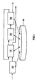
- the Case Base Optimisation Framework includes the Case Base 100, a Test Generator 101, an Optimiser 102, an Evaluator 103 and an Acceptor 104.
- the units 101 to 104 are interactively coupled to the Case Base 100.
- the Test Generator 101 triggers the Optimiser 102, which creates signals.
- the Optimiser 102 activates the Evaluator 103 and Acceptor 104. Signals from Acceptor 104 are channelled back to the Optimiser 102 in order to trigger cyclic activation of the devices.
- the Figures 2 to 7 includes a series of flow diagrams that define the main component activities and data resources that define the behaviour of the new system.
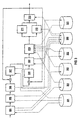
- Figure 2 shows the top-level architecture of the claimed method. It comprises:
- FIG. 1 represents the top level behaviour of the new control system. What is noteworthy is that the system in normal operation will have three possible cycles:
- results of the system are represented as a similarity ordered sequence of previous cases. This provides the basic information that allows the most relevant old sensor values to be extracted from the underlying data base of the technical process. Extracted data can either be presented to a human expert as an aid to manual process control, or as the input to an automated control system to guide computer-based decisions.
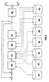
- Figure 3 shows the internal architecture of the training unit 206 of figure 2. It comprises:
- Figure 3 represents the relative complex internal behaviour of the training activity of the invented system. From the raw sensor data, a test and training case base are constructed along with the set of sensor clusters. The system then iteratively refines the case index so that a minimal amount of sensor data is included in the case index without producing a degredation in retrieval accuracy.
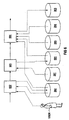
- Figure 4 shows the internal architecture of the central evaluation unit 310 of Figure 3 of the training unit 206 of Figure 2. Further it comprises:
- the evaluation takes each case of the test case base in turn and performs a retrieval from the training case base.
- the resulting retrieval ordering is compared to a precomputed ideal ordering of training cases for the test case.
- a numerical value for the degree of correspondance of the two orderings is computed and added to a combined evaluation value for the whole test case.
- Figure 5 shows the internal architecture of the unit 207, see also 304, used to extract a case base in the top level architecture. It comprises:
- Figure 5 represents the way in which a case base is extracted from the database of sensor values for the technical process.
- the process iterates from a start time to an end time and generates a case at every time point that is defined as "interesting" with with respect to a computed metric.
- the extraction will iterate from the first stored sensor values up to the most recent data.
- the data needs to be segregated into disjoint test and training time periods.
- Figure 6 shows the internal architecture of the unit 208 of figure 2 used to make sensor value predictions. It comprises:
- Figure 6 represents the internal behaviour of the main activity to predict future sensor values.
- the prediction process corresponds to the process of case retrieval.
- the only addition is that the user may first interact with the system in order to select which sensors are currently of interest. Only these sensors are then considered in the retrieval of relevant past cases.
- Figure 7 shows the internal architecture of the retrieval unit 604 of figure 6. It comprises:
- Figure 7 represents the case retrieval process.
- this involves a linear search through all stored cases in a given case base. Each of these cases is compared to a given new case.
- the similarity between an old and new case is based on the summation of similarities of pairs of sensors between the two cases.
- the case index specifies both which sensors are worthy of consideration during retrieval, and how many values for each pair of sensors need to be compared for a reliable similarity measure.
- the result of retrieval is an ordered list of previous cases for the technical process, e.g. cement kiln.
- the one or more most similar cases provide the basis on which an evaluation of the most likely future state of the technical process can be made and, consequently, the appropriate control decisions made.
- the invented system could act as a part of a fully automated control system
- the main mode of operation is in collaboration with a human expert
- the invented control system presents the expert with the retrieved cases in a clearly understandable format, i.e. a graphical plot, and the human expert makes the informed control decisions.
- the system includes a general-purpose viewer for browsing the cement kiln database.
- the preceding and projected periods of a retrieved case are super-imposed as vertical lines onto a more continuous plot of sensor values.
- the browser allows a much longer time period into the past to be viewed than defined by a case's preceding period, in turn, enabling a more complete understanding of the similarity between the current situation and a retrieved case. It is also possible to view beyond the projected period for the previous case to get a longer prediction for the future behaviour of the cement kiln.
- the invented system is often capable of predicting long-term trends in a technical process.
- the invented system generally made predictions concerning the cement kiln that remain valid for longer than the default 1 hour projection periods of cases.
- Results Plot of Figure 8 are a typical example of the results of the new system, during evaluation period.
- Figure 8 shows, on the right-hand side, the prediction made for three selected sensors, sensor 41, sensor 59 and sensor 92 for an evaluation case selected by a human expert.
- the actual data is plotted alongside the predicted data in order to enable comparison - in normal operation, in contrast to the evaluation phase, beyond the similarity time period, only predicted values will be available and hence, displayed.
- Figure 8 illustrates a number of key characteristics of the system:
- the system is a unique attempt at applying CBR technology to the task of sensor prediction within a technical process, specifically a cement kiln.
- the advantages that the approach provides are as follows:
- the potential for this technology is very high.
- the cement kiln application itself is open to future extension.
- Within the underlying data archive are also recorded the control decisions made by the human experts monitoring the cement kiln. Therefore, in retrieving a previous case, the system may not only provide the means for predicting future kiln behaviour, but also for reusing control decisions. This may provide the basis for a more automated control system with cement factories.
- the system could be used as a training system for new human controllers, allowing them to investigate how existing experts actually responded in various situations.
- time-stamped quality metrics are also routinely stored. For example, samples of the output cement clinker are routinely taken and tested in a laboratory. The results of these tests allow classification to be made of how successfully the cement kiln had performed at any given time. Such evaluations could be incorporated into the case retrieval mechansim to classify cases as "good” or "bad". The system could, therefore, guide a user towards reusing successful control decisions while warning against the reuse of control decisions that had proven unsuccesssful in the past. This should lead to an overall improvement in the performance of the cement kiln.
Landscapes
- Engineering & Computer Science (AREA)
- Artificial Intelligence (AREA)
- General Physics & Mathematics (AREA)
- Automation & Control Theory (AREA)
- Evolutionary Computation (AREA)
- Medical Informatics (AREA)
- Software Systems (AREA)
- Physics & Mathematics (AREA)
- Health & Medical Sciences (AREA)
- Computer Vision & Pattern Recognition (AREA)
- Testing And Monitoring For Control Systems (AREA)
- Curing Cements, Concrete, And Artificial Stone (AREA)
- Investigating Or Analyzing Materials By The Use Of Fluid Adsorption Or Reactions (AREA)
- Waste-Gas Treatment And Other Accessory Devices For Furnaces (AREA)
- Feedback Control In General (AREA)
- Investigating Or Analyzing Materials Using Thermal Means (AREA)
- Investigating And Analyzing Materials By Characteristic Methods (AREA)
Abstract
Description
- The invention concerns a method and an apparatus for a case-based reasoning (CBR) system,especially developed for the task of sensor value prediction within a cement kiln control system.
- Providing accurate predictions of the cement kiln behaviour for a limited period into the future, e.g. approx. 1 hour, can enable a human controller of the cement kiln to make more informed decisions, as well as providing a basis for more automated control within a cement making plant. The invention provides an alternative to existing technologies, such as rule-based control systems, that require prohibitively high installation and maintenance costs.
- As part of an existing system which provides extensive support facilities for the control of a cement production plant, all sensor data for the cement kiln and related machinery are routinely stored within a database. The data is represented as time-stamped floating-point numbers.
- As an example of the amount of data that needs to be processed in a sensor-based technical process; the sensor sampling rate inside a cement kiln is typically once a minute or more frequent, there are typically over 400 sensors in the cement kiln and related apparatus, and the data archive can contain in access of 1 year's storage of data. This means that the raw data can be of the order of 108 -> 109 floating point numbers. Therefore, any automated method that exploits this data to perform sensor value prediction needs to be able to cope with a large amount of unstructured sensor data.
- The invention is most suited to technical processes that involve human intervention. Typically, the cement kiln in an active cement production plant is monitored and controlled by a human expert, roughly every 10-15 minutes. Due to the high numbers of sensors involved, it is difficult for a human expert to get an adequate over-view of the status of the kiln and, therefore, there is a need for automated support in the analysis task. In particular, when exceptional behaviour occurs, e.g. sensor values going out of predefined ranges, or an abrupt change in sensor values, support is required to determine both what the likely/possible consequences are of the exceptional behaviour and what corrective actions the human expert should carry out. In order to support this, an automated system is required that can accurately project the values of all sensors for a significant time period, e.g. >1 hour, into the future.
- Nevertheless, the user may, at any one time, dynamically select a reduced subset of signature sensors that are considered to contain the most salient information to characterise the current state of the technical process. Hence, the automated prediction system must be flexible enough to react to this dynamic user selection.
- The sensor data collected for a technical process can often be problematic. For example, due to the relative close proximity of many of the sensors within the cement kiln, there is significant redundancy in the information that is represented in the data stored for different sensors. Some level of random noise in the recorded data must also be tollerated. Perhaps more significantly, it cannot be guaranteed that all values for all sensors are always available. There are some periods of time where no sensor values are recorded, e.g. due to a failure in the database. More commonly, missing values will occur for a single sensor for a period of time,e.g. due to a failure in the sensor itself. These impurities in the raw data must be tollerated by the prediction system.
- The final complexity of the problem is that each application of the prediction system to a new instance of a technical process will require some recalibration. For example, each cement kiln has its own behaviour characteristics. Indeed, the set of sensors contained is likely to change from cement kiln to cement kiln. Hence, the sensor-value prediction system must be newly adapted to each cement plant in which it is installed; a costly procedure for any technique that is model-based. Furthermore, as for many other types of manufacturing apparatus, a single individual cement kiln is subject to ageing. In other words, the behavioural characteristics of a single cement kiln are known to drift gradually over time. Hence, any behavioural model developed for an individual cement kiln must be periodically refitted to adapt to these changes; this is also a potentially costly maintenance problem.
- Model-based techniques, in conjunction with Artificial Intelligence technology, such as Neural Networks and Fuzzy Logic, represent the state-of-the-art for automated control systems for cement plants. The main problem with this type of approach is that the general model of the technical system embedded in the prediction system must be adapted and parameterised by highly-skilled experts in order to be applied within a particular cement plant. In addition, due to drift in the behaviour of a single cement kiln over time, the model needs to be periodically maintained, e.g. re-parameterised, so as to remain reliable over time. The disadvantages of high application and maintenance costs are likely to be encountered by any model-based technique.
- A general alternative to hand-constructed and adapted models are machine learning techniques that can be trained on existing data. The most popular of such machine learning approaches are artificial neural networks that have been successfully employed to perform diagnostic tasks based on sensor data in similar application fields to that of this invention. Nevertheless, some fundamental problems remain with artificial neural networks that serious prohibit their use for the cement kiln control application:
- Ability to deal with missing data: Some techniques exist for generation of missing sensor values, such as linear interporlation. Nevertheless, the degree of noise in the application data may hinder the training of artificial neural networks. Furthermore, it is not clear how an artificial neural network can deal with the dynamic selection of a subset of relevant sensors.
- Interpretation of results: The basis behind the predicted by a human controller results generated by an artficial neural network are not easily open to human inspection by a human expert. Hence, a control expert is unable to assess the reliability of the prediction. For this reason, neural networks are better suited to completely automated applications where human inspection of the predictions is not required.
- Ability to predict exceptional behaviour: A trained artificial neural network is generally good at recognising the general trends that frequently re-occur within the training data but poor at reproducing rarely occurring, exceptional circumstances. Nevertheless, rare behaviour is often the most important to predict with respect to the state of the art, the objects of the invention are; a new method and a new apparatus for process optimisation, especially in a cement kiln, based on the data produced by sensors.
-
EP 0 582 069 A2 discloses a method for control of a process having manipulated and controlled variables with the controlled variables having target values which depend on the adjusted value of said manipulated variables. The process is controlled in real time through a process controller under the operation of a computer. The method of control comprising the-steps of establishing a first performance index to compute the absolute value of the deviation for each control variable in the process from its target value over a specified time horizon; generating a first linear programming model the solution of which minimizes said first performance index; solving the first linear programming model; establishing a second performance index to compute the absolute change in the value of each manipulated variable from its previous value for each control variable over a specified time interval; generating a second linear programming model the solution of which minimizes said second performance index; incorporating at least one dynamic constraint in said second linear programming model computed from the solution of said first linear programming model and being equal to a value above zero and of no greater than the value of the solution of said first linear programming model plus a predetermined amount; solving said second linear programming model with said dynamic constraint; and adjusting the manipulated variables in response to the solution of said second linear programming model to drive said controlled variables toward the target values. -
EP 0 745 916 A1 discloses a method for controlling a technical process, whereby the process variables a measured as data sets and compared with stored data sets and/or computed for getting control parameters for process optimization. The data sets are stored in memories and such cases of data sets are chosen which fulfil a goal. The cases are stored in an m-dimensional space as a polytope whereby only such data sets which are laying on the surface of a polytope are used for getting control parameters. -
EP 0 529 307 A1 discloses a method for controlling the operation of liquefied neutral gas process which utilizes gas turbine-driven refrigeration compressors. The method comprises the steps of determining the ambient air temperature at the location of the liquefaction process at a given time; determining the optimum operation conditions of the liquefaction process including the set point of the feedback control loop at the given time, and operating the liquefaction process at the optimum operating conditions including the set point of the feedback control loop; predicting the ambient air temperature at the future time; determining new optimum operating conditions of the liquefaction process including a new set point of the feedback control loop at the future time, and changing the optimum operating conditions to the new optimum operating conditions including changing the set point to the new set point; operating the liquefaction process and the new optimum operating conditions including the new set point; and repeating the aforementioned steps at a time interval defined by the time difference between the given time and the future time. -
EP 0 477 490 A2 discloses an approximate reasoning apparatus where data representing a relationship between factors and conclusions which have occurred is accumulated in a memory, thereby making it possible to revise a knowledge base, which has already been established, e.g. at the designs stage, using the accumulated data. Since the knowledge base is revised using data representing the relationships between factors and conclusions which actually have occurred, more accurate approximate reasoning becomes possible. In addition, since revision of the knowledge base is performed automatically, maintenance of a knowledge base is possible without the aid of experts. - US 5,574,638 discloses a method which provides robust control of a process, comprising the steps of calculating a set of scale factors for the manipulated variables and the process variables. The controller is initialized with the set of scale factors, the scale factors determining the relative importance to the process of the manipulated variables and the process variables. The robust control is initialized to have predetermined constraints of the manipulated variables and the control variables. The present values of the manipulated variables and the controlled variables are then obtained. New values are calculated for the controlled variables for a predetermined number of points in the future such that the values of the controlled variables are within the predetermined range thereby obtaining an optimum robustness of the resultant controller.
- WO 93/21587 discloses a machine learning system implementing a case-based-like reasoning system with a relational data base. A relational data base may comprise a set of records and a set of fields, each field in each record may comprise a value, such as numeric value. Cases in a case-based reasoning system may be represented by records like those in the relational data base, and a feature of a case maybe represented by the fields of the record. A case in the case base may be represented by records in the relational data base while cases which are encountered and which may be matched to the case base may be represented by records which may be matched to the relational data base. When a case is to be matched to the case base a search designation may be composed and applied so as to produce a search set of records which represent similar cases. One of these records may be chosen as the predictive record which represents the case which is the best match. When the record which represents the best match is chosen the predicted fields may represent the prescribed action for that case. For example in a help desk system the predicted fields may indicate a voice response message and a selection menu to be presented to the caller.
- US 5,587,897 discloses an optimization method comprising a step for inputting an objective function which includes a parameter to be optimized and is an object for searching an optimal solution, a required precision indicating a precision required in searching the optimal solution and a search region for searching the optimal solution for the object function to make that objective function into a convex function; a step for inputting said convex objective function to detect a search start point for starting a search of the optimal solution from said search region of the optimal solution, and a step for detecting the optimal solution based on the detected search start point.
- These objects are disclosed in the process claims and the corresponding apparatus claims.
- The invention will be further described in connection with the illustrations containing an apparatus overview, six flow charts and an example plot of practical results. The specific content is as follows:
- Figure 1
- an apparatus for case base optimisation
- Figure 2
- the top level flow of the method executed in the apparatus of figure 1
- Figure 3
- the training flow
- Figure 4
- the evaluation flow
- Figure 5
- the extract case base flow
- Figure 6
- the generate sensor predictions flow
- Figure 7
- the case retrieval flow
- Figure 8
- a diagram with results of the inventive method and apparatus.
- The approach used in the system of the invention is to apply case-based reasoning (CBR) to sensor prediction. The principle behind CBR is one of reuse of old problem solutions. The knowledge base of the CBR system is a collection of problem solving cases. Each case is composed of two distinct parts:
- A problem description - the collection of features (symptoms) that characterise the problem
- The problem solution - a description of what the solution to the problem was and, optionally, how the solution was derived.
- The principle behind CBR is that similar problems have similar solutions. Hence, in order to solve a new problem, where only a problem description exists, this new problem is compared to all existing problems via some domain specific similarity function. Once one or more similar, previously solved problems, i.e.cases, have been found, the solutions are re-applied to the new problem.
- The system described here is unique in the way it applies CBR to the problem of sensor prediction in technical processes. The case base is built directly on top of the archive of sensor data in such a way that the cases within the case base and the actual sensor data are coupled. This means that the system can directly exploit the most up-to-date sensor data without any need for manual modification. In this way, the system responds to drift in the behaviour of the technical process, as reflected by the sensor data.
- The system matches the current state of the technical process, as reflected in the sensor data, with all past cases representing example previous states in order to extract the most similar previous state(s) of the technical process. A number of alternative previous states can be retrieved simultaneously for the current state and presented as possible alternative predictions to a human expert. There is a relatively high degree of flexibility in the retrieval of previous states; it can be based on a comparison across all 400+ sensors or on a small number of signature sensors selected by a user. The current state and each previous state can be graphically plotted. For example, because actual cement kiln data are re-used as the basis for the prediction, the results can be easily interpreted by a human expert.
- The CBR approach has proved successful and robust in the cement kiln application. Experimental trials have shown that the system is capable of making accurate predictions of up to and beyond 1 hour into the future. Furthermore, experiments have verified that a CBR approach is capable of predicting both general trends, such as stable sensor values as well as rare events, such as global changes to the state of the cement oven triggered by a single event.
- In the system, the cases are defined as partially virtual views of the data in the sensor data archive. Each sensor can be thought of as a time-stamped sequence of values. A single case represents a particular time-window within the data for all sensors. There are two consecutive time periods within a single case's time window:
- The Preceding Period - representing the sequence of sensor values to be used to match a previous case to a current situation in the technical process,e.g. cement kiln
- The Projected Period - representing the state of the technical process,e.g. cement kiln for a length of time immediately following the preceding period.
- In a second version of the invention, a number of more abstract features e.g. number of oscillations in the preceding period, are automatically extracted from the sensor data and included as part of the case description, in order to improve the accuracy of case matching.
- In the terms of the earlier description of CBR, the preceding period represents the problem description for a case and the projected period represents the problem solution. The actual time span for preceding and projected periods is defined by system parameters and can be configured for a particular application.
- The time-point that marks the boundary between preceding and projected periods will be refered to as the Case Time in this text. After a previous case has been retrieved for the current situation in a technical process, e.g. the process of the cement kiln, its case time will be synchronised to the latest recorded sensor value in order that its projected period can then be used as a prediction for the future behaviour of the technical process.
- In principle, a new case can be created in the case base for every time point at which a separate sensor value is recorded. In reality, this will lead to an excessive number of overlapping cases. In practise, because of the usually slow rate of change of state within a cement kiln, only one or two cases are typically required to characterise the behaviour over a particular hour, though on exceptional occasions a much higher density of cases is required, e.g. when the behaviour of the kiln is under-going a major change. In order to achieve best prediction performance, a probablistic distribution of cases throughout the sensor data archive is employed. The probability of creating a case at a given time point depends on two factors:
- The period of time since the last case was created
- A metric of the amount of information in the sensor values, e.g. degree of fluctuation, in the vicinity of the time point.
- A typical application will contain several thousand previous cases. Despite the relatively lax constraints on the time required to generate a new prediction of the order of 1-2 minutes, reading individual sensor values from a database is still too slow. Therefore, some sensor data must be reproduced within the local memory of the system to facilitate case retrieval. This is refered to as the Case Index. In the invented system, the case index represents the minimal amount of sensor information from the preceding period that is required to produce reliable retrieval of previous cases. The extraction of the appropriate case index is achieved via a fully automated optimisation technique, (described below). It is important to note, however, that the system can operate successfully,although sub-optimally, even without a Case Index, i.e. using all sensor information for case retrieval. Hence, the case base optimisation system can be seen as a process that is first used to improve system performance after the system has been in operation for some weeks and may be used as an off-line means of occasionally recalabrating the control system in response to gradual changes in the behaviour of the technical process,e.g. the process of the cement kiln.
- The goal of the case-based optimisation is to minimise the amount of data replicated within the case base without reducing the quality of case retrieval. Data reduction means:
- i) discarding irrelevant sensors;
- ii) for relevant sensors, determining the minimum time period
of previous values of that sensor that needs to be compared
for an accurate retrieval. The reduction of data is important
for several practical reasons:
- Memory Usage is Reduced (Compression) - the the amount of data that can be held in the working memory of the system without encountering high degrees of memory paging is bounded by the limitations of current computing hardware technology.
- Retrieval Speed - by comparing less sensor values per case, the retrieval of the most similar previous cases is made more rapid
- Prediction Quality - There are a number of reasons why reducing the amount of explicitly stored data per case increases the accuracy of the system. Firstly, the limitations on the size of working memory effectively limits the number of cases that can be generated on top of a given data archive - i.e. it determines how sparsely cases are spread through the data archive. By reducing the amount of data per case, more cases can be created and hence the average time period between generated cases is reduced. This, in turn, leads to a greater prediction accuracy as, on average, a more exact time-alignment of previous cases to the current situation is possible. In addition, another benefit of the optimisation process is that it tends to eliminate those sensors which have the lowest information content, i.e. have high degrees of noise, or have highly redundant information with respect to other sensors. The elimination of irrelevant information generally improves retrieval accuracy with respect to the situation where all sensor values are used.
-
- The case base optimisation starts with a training archive of sensor data from the technical process, e.g.the process of a cement kiln. On top of this data, a training case base and a test case base are generated, disjoint from one another, i.e. there is no overlap in the case time-span. Initially, the index for each case base contains all sensors and all values for each sensor within the preceding period.
- Because the test cases are based on archived data, the actual behaviour of each test case in its projected period is known. Therefore, for each test case, it is possible to predetermine which training cases have the most similar projected period, e.g. using a standard measurement of curve closeness, such as Root Mean Squared (RMS) error. Hence, the ideal retrieval results for each test case, i.e. an ordering across all training cases, can be generated.
- For a given index, the actual retrieval ordering of training cases for a given test case is achieved via a comparison of the preceding periods. A general measure of the "fitness" of a given index description for a given training case base and test case base is given by the average closeness of the retrieval ordering of training cases per test case, with respect to the precomputed ideal orderings of training cases. This "fitness" is computed at each cycle in the case base optimisation process.
- For a single optimisation cycle, a single sensor is randomly selected and the number of values for that sensor within the index of each case is halved. The resulting "fitness" of the case base is then determined. If there is no reduction in case base "fitness" then the reduction in the number of sensor values is accepted, else the failed number of values becomes a lower bound for the number of required values for that sensor. Thus, the optimisation converges via a strict ,,hill-climbing,, approach - i.e. the amount of information in the sensors that is used is monotonically reduced while no degradation in retrieval quality is tolerated. Strict "hill-climbing" is is implemented mainly to ensure efficiency of the optimisation process - better results may be obtained with a variation of the invention that uses a more global optimisation algorithm, such as simulated annealing.
- The optimisation process continues until the required number of values for each sensor converges - because of the strict "hill-climbing" nature nature of the algorithm, convergence is guaranteed. Irrelevant sensors will end up with zero required values.
- Initial experiments on the cement kiln data reveal that roughly only 50% of all sensors need to be included within the case index. Importantly, the amount of information required for each remaining index sensor is highly variable. Most included sensors require only the most recent one or two values to be compared while a small number of key sensors require a high number (30 -> 60) of values. From the initial experiments, an overall compression to only 5-10% of the initial set of all sensor values is achieved within the optimised case indices. Effectively, this means 10-20 times more cases can be included within the case base for a given working memory capacity, hence increasing accuracy of the system. Accuracy is also increased through the elimination of noise.
- Many CBR systems pre-structure their case memory to support rapid case retrieval, e.g. through the use of decision trees to segregate the underlying cases. Unfortunately, for this invention, the massive amount of data stored in each case, coupled with the need for flexibility in case retrieval, e.g. the run-time selection of relevant sensors by a user, makes such pre-structuring of memory extremely difficult. Hence, the implemented retrieval mechansim involves a linear search through all stored cases. A similarity function computes a normalised similarity value for each stored case, with respect to the current state of the technical process, e.g. cement kiln, and with respect to the sensors selected as relevant by a user. The result of retrieval is an imposed, similarity-based ordering across all stored cases. A more efficient variation of the invention is to imploy this ordering just for a limited number,e.g. 20, of the best previous cases.
- The key to retrieval is the similarity function used. The similarity function operates upon the case index. The similarity of the current situation to a stored case is equal to the normalised sum of the similarities of each pair of corresponding index sensors. The similarity in the value sets for two matched sensors can be computed by standard mathmatical functions, e.g. RMS.
- In an extended version of the invention, sensors are represented not just by their value sets but also by features extracted from these value sets,e.g. number of fluctuations in the preceding period. Such features can also be compared using specialised similarity functions and combined with the similarity between value sets to give an overall similarity measure between two matched sensors. The inclusion of such extracted sensor features was shown to improve the overall accuracy of the retrieval mechanism.
- In Figure 1, the Case Base Optimisation Framework is shown and includes the
Case Base 100, aTest Generator 101, anOptimiser 102, anEvaluator 103 and anAcceptor 104. Theunits 101 to 104 are interactively coupled to theCase Base 100. TheTest Generator 101 triggers theOptimiser 102, which creates signals. TheOptimiser 102 activates theEvaluator 103 andAcceptor 104. Signals fromAcceptor 104 are channelled back to theOptimiser 102 in order to trigger cyclic activation of the devices. - The Figures 2 to 7 includes a series of flow diagrams that define the main component activities and data resources that define the behaviour of the new system.
- Below, Figures are described separately.
- Figure 2 shows the top-level architecture of the claimed method. It comprises:
- a
database 201 containing all sensor data; - a
database 202 that contains groupings (clusters) of the sensors; - a
database 203 that contains the generic description (index) of each case in terms of the required sensor values; - a
database 204 that contains all individual cases used by the prediction and control system; - a
database 205 that contains the temporary collection of retrieved cases that match the current state of the cement kiln; - a
training unit 206 that generatesdatabases - a
case extraction unit 207 that extracts thecase base 204 used by the control system from thesensor data 201; - a
prediction unit 208 that generates a set of predictions, namelydatabase 205, based on the information stored indatabases - a
unit 209 that uses the predictions stored indatabase 205 along with the sensor data in 201 as the basis for automated control of the cement kiln; - a
unit 210 that uses the predictions stored indatabase 205 along with the sensor data in 201 as the basis of a graphical display of the predictions in order to assist a human controller. - Figure 2 represents the top level behaviour of the new control system. What is noteworthy is that the system in normal operation will have three possible cycles:
- The long-term maintenance cycle may be carried out once in the installation of the system then rarely - if at all - to completely retrain the system in response to major changes in the underlying technical process,e.g. cement kiln. Amongst other things, the system will learn a new, optimal case index.
- The medium-term maintenance cycle allows new cases to be added to the case base but does not change the definition of a case index. This cycle may be, for example, carried out daily to keep the case base up to date.
- The normal prediction cycle represents the normal usage of the new system. This cycle may be performed as regularly as every minute in order to keep the prediction generated by the system up to date.
- The results of the system are represented as a similarity ordered sequence of previous cases. This provides the basic information that allows the most relevant old sensor values to be extracted from the underlying data base of the technical process. Extracted data can either be presented to a human expert as an aid to manual process control, or as the input to an automated control system to guide computer-based decisions.
- Figure 3 shows the internal architecture of the
training unit 206 of figure 2. It comprises: - a
database 301 that is a temporary case base used to evaluate predictions during the training period; - a
database 302 that is a second temporary case base of cases for which predictions must be made during the training period; - a
database 303 that stores the best possible prediction for each test case extracted from the sensor data ofdatabase 201 of figure 2; - a
case extraction unit 304, which is a variation ofunit 207 of figure 2, that separates the sensor data stored indatabase 201 of figure 2 in order to create the twocase bases - a
unit 305 that generates the groups of sensors stored indatabase 202 of figure 2, based on correlated trends in the sensor values stored indatabase 201; - a
unit 306 that creates the initial state of the generic case index stored indatabase 203 of figure 2, in terms of the maximum number of sensor values that should be considered in a single case. - a
unit 307 that evaluates the sensor data of 201 in order to determine the best possible predictions of each test case, stored indatabase 303; - a
unit 308 that selects a sensor at random and aunit 309 that temporarily reduces the number of values of the corresponding sensor that are included within the generic case index stored in 203; - an
evaluation unit 310 that determines if the previous reduction in sensor values byunit 309 led to an improved prediction performance with respect to the ideal results - a
unit 311 that makes permanent the last change made by 309 and stored indatabase 303 in the case of a positive evaluation byunit 310 and aunit 312 that reverses the last change made byunit 309 in the case of a negative evaluation byunit 310; - a
unit 313 that determines when the training period should terminate - i.e. no further improvement in the generic case index ofdatabase 203 are possible. - Figure 3 represents the relative complex internal behaviour of the training activity of the invented system. From the raw sensor data, a test and training case base are constructed along with the set of sensor clusters. The system then iteratively refines the case index so that a minimal amount of sensor data is included in the case index without producing a degredation in retrieval accuracy.
- The heart of the training process is the evaluation activity shown in Figure 4. Figure 4 shows the internal architecture of the
central evaluation unit 310 of Figure 3 of thetraining unit 206 of Figure 2. Further it comprises: - a
database 401 that temporarily represents the current cases selected from thetest case base 302; - a
unit 402 that selects each of the test cases stored in 302 of figure 3 in turn and places them in 401; - a
unit 403 that carries out a case retrieval from the training cases stored in 301, based on the current test case in 401 and on the current state of the generic case index in 203, in order to create the temporary retrieval results stored in 205 of figure 2; - a
unit 404 that determines which of the ideal results stored in 303 of figure 3 are applicable for the test case currently stored in 401; - a
unit 405 that computes a numeric measure of the difference in the prediction made for the test case of 401 by the corresponding retrieval results ofdatabase 205 of figure 2, with respect to the corresponding ideal results indatabase 303 of figure 3; - a unit 406 that converts the combined numeric evaluation across all test cases of 302 into a boolean decision as to whether or not the evaluation was positive.
- The evaluation takes each case of the test case base in turn and performs a retrieval from the training case base. The resulting retrieval ordering is compared to a precomputed ideal ordering of training cases for the test case. A numerical value for the degree of correspondance of the two orderings is computed and added to a combined evaluation value for the whole test case.
- Figure 5 shows the internal architecture of the
unit 207, see also 304, used to extract a case base in the top level architecture. It comprises: - a
unit 501 that computes a numeric "interest" value for each time point of the sensor values stored indatabase 201; - a
unit 502 that determines whether the interest level of each time point exceeds a given threshold; - a
unit 503 that is used whenunit 502 determines that the threshold has been exceeded in order to create a new case and to insert the case into thedatabase 204; - Figure 5 represents the way in which a case base is extracted from the database of sensor values for the technical process. The process iterates from a start time to an end time and generates a case at every time point that is defined as "interesting" with with respect to a computed metric. Normally, the extraction will iterate from the first stored sensor values up to the most recent data. For the generating of training and test case bases, the data needs to be segregated into disjoint test and training time periods.
- Figure 6 shows the internal architecture of the
unit 208 of figure 2 used to make sensor value predictions. It comprises: - a
database 601 that represents a new case for which a prediction must be made; - a
unit 602 that allows a subset of all sensors to be determined as relevant for retrieval, based on the sensor groupings stored indatabase 202; - a
unit 603 that generates a new case indatabase 601, representing the most recent sensor values stored indatabase 201; - a
retrieval unit 604, that carries out case retreival for the new case indatabase 601 from thecase base 204 based on the information stored indatabases database 205. - Figure 6 represents the internal behaviour of the main activity to predict future sensor values. The prediction process corresponds to the process of case retrieval. The only addition is that the user may first interact with the system in order to select which sensors are currently of interest. Only these sensors are then considered in the retrieval of relevant past cases.
- Figure 7 shows the internal architecture of the
retrieval unit 604 of figure 6. It comprises: - a
database 701 in which each stored case is temporarily stored during the retrieval process; - a
database 702 that represents the values for a selected sensor of the old case stored indatabase 701; - a
database 703 that represents the values for a selected sensor of the new case stored indatabase 601 of figure 6; - a
unit 704 that clears the retrieval results stored indatabase 205 prior to the new retrieval process; - a
unit 705 that selects each of the cases stored indatabase 204 in turn and places the old case indatabase 701; - a
unit 706 that selects each corresponding pair of sensors from the old case ofdatabase 701 and new case ofdatabase 601 in turn, taking into account the selected sensor groupings in 202, and then extracts the appropriate number of values in accordance with the generic case index stored indatabase 203, storing the sensor value sequences indatabases - a
unit 707 that computes a numeric similarity value for the correspondence between the sensor value sequences stored indatabases - a
unit 708 that adds the results generated byunit 707 to an internal case similarity value; - a
unit 709 that adds an old case fromdatabase 701 to the new case retrieval results stored indatabase 205, ensuring that the old cases are ordered with respect to descending similarity to the new case indatabase 601. - Figure 7 represents the case retrieval process. Currently, this involves a linear search through all stored cases in a given case base. Each of these cases is compared to a given new case. The similarity between an old and new case is based on the summation of similarities of pairs of sensors between the two cases. The case index specifies both which sensors are worthy of consideration during retrieval, and how many values for each pair of sensors need to be compared for a reliable similarity measure.
- As stated above, the result of retrieval is an ordered list of previous cases for the technical process, e.g. cement kiln. The one or more most similar cases provide the basis on which an evaluation of the most likely future state of the technical process can be made and, consequently, the appropriate control decisions made. While, in principle, the invented system could act as a part of a fully automated control system, the main mode of operation is in collaboration with a human expert - the invented control system presents the expert with the retrieved cases in a clearly understandable format, i.e. a graphical plot, and the human expert makes the informed control decisions. This frees the human expert from the time consuming, error-prone and laborious task of trying to locate the most similar previous states of the technical process, e.g. the process of the cement kiln, as stored in the data archive, while enabling their intuition and understanding of the technical process to be best exploited.
- An example of the graphical display is given in Figure 8.
- In reality, the user is not restricted to just looking at the time periods defined by the scope of a case. The system includes a general-purpose viewer for browsing the cement kiln database. The preceding and projected periods of a retrieved case are super-imposed as vertical lines onto a more continuous plot of sensor values. Thus, the browser allows a much longer time period into the past to be viewed than defined by a case's preceding period, in turn, enabling a more complete understanding of the similarity between the current situation and a retrieved case. It is also possible to view beyond the projected period for the previous case to get a longer prediction for the future behaviour of the cement kiln. While this is not generally recommended, as the accuracy of prediction generally decreases with distance into the future, the invented system is often capable of predicting long-term trends in a technical process. For example, the invented system generally made predictions concerning the cement kiln that remain valid for longer than the
default 1 hour projection periods of cases. - The "Results Plot" of Figure 8 are a typical example of the results of the new system, during evaluation period. Figure 8 shows, on the right-hand side, the prediction made for three selected sensors,
sensor 41,sensor 59 andsensor 92 for an evaluation case selected by a human expert. The actual data is plotted alongside the predicted data in order to enable comparison - in normal operation, in contrast to the evaluation phase, beyond the similarity time period, only predicted values will be available and hence, displayed. - Figure 8 illustrates a number of key characteristics of the system:
- Predictions often remain valid longer than the required 1 hour prediction period - the example only begins to degrade in quality after about 3 hours into the future
- Time alignment between prediction and actual behaviour is
not always exact - e.g. approximately 10 minutes difference
in the predicted and actual rising edge of
sensor 92 can clearly be observed - The system successfully captures relationships between
sensors - for example, the successful pediction of the
rising edge of
Sensor 92 cannot be attributed to similarity in this sensor alone, as the preceding values forsensor 92 are all zero. The similarity in the two situations must stem from the other sensors, eithersensor 41 or 53, respectively from one or more of the undisplayed sensors. - The system is a unique attempt at applying CBR technology to the task of sensor prediction within a technical process, specifically a cement kiln. The advantages that the approach provides are as follows:
- Predictions are based on real-life examples taken from the history of the cement kiln. Therefore, the predictions can be inspected and understood by a domain expert.
- The system is directly coupled to the underlying sensor data in the data archive; therefore, the system automatically responds to any drift in the cement kiln behaviour.
- The system requires no general domain model to perform predictions, therefore installation and maintenance costs are low.
- The system is able to predict general trends and exceptional events.
- The system provides a set of alternative predictions for each new situation. The CBR assumption; that similar problems require similar solutions; has proved valid for the cement kiln application. Retrieval of similar situations leads to predictions that generally remain valid for a long period of time, e.g. more than one hour, and capture interesting details within the more general trends of the sensors.
- Not only is the system a general innovation in its usage of CBR for this type of problem, a number of more technical innovations where required in order to deal with the massive amount of raw data involved:
- The definition of semi-virtual cases as time-spanned views of the underlying sensor data
- A self-optimisation algorithm for the case base so as to extract the minimal amount of required index information.
- The potential for this technology is very high. The cement kiln application itself is open to future extension. Within the underlying data archive are also recorded the control decisions made by the human experts monitoring the cement kiln. Therefore, in retrieving a previous case, the system may not only provide the means for predicting future kiln behaviour, but also for reusing control decisions. This may provide the basis for a more automated control system with cement factories. Alternatively, the system could be used as a training system for new human controllers, allowing them to investigate how existing experts actually responded in various situations.
- Moreover, within the underlying data archive, time-stamped quality metrics are also routinely stored. For example, samples of the output cement clinker are routinely taken and tested in a laboratory. The results of these tests allow classification to be made of how successfully the cement kiln had performed at any given time. Such evaluations could be incorporated into the case retrieval mechansim to classify cases as "good" or "bad". The system could, therefore, guide a user towards reusing successful control decisions while warning against the reuse of control decisions that had proven unsuccesssful in the past. This should lead to an overall improvement in the performance of the cement kiln.
- The design of the system is in no way specialised to the needs of the cement kiln application. A highly generic model of time-trended sensor data is used for the definition of cases. Therefore, the system could easily be re-applied to the prediction of sensor data in other domains. The conditions under which the system is most likely to be the best implementation choice are:
- Sensor data is routine stored in a machine-readable data archive
- The complexity of the system makes model-based techniques too expensive or practically impossible
- The time constraints on the generation of a prediction are not too strong - The time taken to make a prediction must be significantly less than the time period for which that prediction remains valid. Assuming a 15 minute monitoring cycle of a cement kiln, the system is currently designed to make a prediction in 1-2 minutes. This speed will depend on the available computing hardware, e.g. size of memory, and on the size and complexity of the data stored in the data archive. The system is currently not, however, suitable for applications that require very rapid (<< 1 second) response.
- The interpretability of predictions by a human expert is a key factor. Therefore c.f. neural networks, etc. are used.
- The reapplication of the CBR approach to other types of time-trended information, other than sensor-based data, should also be possible. Examples of such information include: share-price trends, market trends, user demands within an electricity supply network, etc.
Claims (16)
- Method for control of a technical process, in particular for control of a cement kiln, whereby the technical process generates a large number of sensor values, which are recorded and stored in a sensor data archive (201), whereby cases are generated out of the recorded sensor data representing the behavior of the technical process, whereby a case base is extracted from the sensor data archive (201) containing at least a subset of all cases generated previously, whereby a new case is generated representing a current state of the technical process for which a prediction has to be made, and whereby the new case is compared with the previous cases as a basis of prediction for the future behavior of the technical process, characterized by recording time-stamped sequences of sensor values and storing the data in the sensor data archive (201), generating cases representing a time-interval within the data for all sensor values and being defined by a case time marking the boundary between a preceding and a consecutive projected period of said time-interval, determining a case similarity value for each of the previous cases from the case base to the new case by comparing the sensor value sequences of the preceding periods of said new case and said previous cases, carrying out case retrieval from the case base by ordering the previous cases with respect to descending similarity to the new case, synchronizing the case time of the one or more most similar case to the latest recorded sensor value of the new case and using the projected period of the most similar case as a prediction for the future behavior of the technical process
- Method according to claim 1, characterized by displaying the predicted behavior of the technical process as a basis on which a control decision can be made by a human expert.
- Method according to claim 1 or 2, characterized by selecting a relevant subset of all sensors which are currently of interest and using only the value sequence of the relevant sensors for determining case similarity values.
- Method according to anyone of claims 1 to 3, characterized in that the determination of a case similarity value comprising the steps of selecting a corresponding pair of sensors from the previous case and the new case, extracting the number of sensor values in accordance with a case index, said case index specifying which sensors are worthy of consideration during case retrieval and how many values for each pair of sensors need to be compared for a reliable similarity determination, computing a numeric similarity value for the correspondence between the sensor value sequences of the selected pair of sensors according to the case index, summing up the numeric similarity values for all pairs of sensors according to the case index to the case similarity value.
- Method according to anyone of claims 1 to 4, characterized in that the extraction of a case base from the sensor data archive (201) comprising the steps of computing a numeric interest value for each time point of the sensor values, determining whether the interest value of each time point exceeds a given threshold, creating a case when the threshold has been exceeded and insert the case into the case base.
- Method according to anyone of claims 1 to 4, characterized in that the extraction of a case base from the sensor data archive (201) comprising the steps of employing a probabilistic distribution of cases throughout the sensor data archive (201), whereby the probability of creating a case at a given time point depends on the period of time since the last case was created and a metric of the amount of information in the sensor values in the vicinity of said time point.
- Method according to anyone of claims 4 to 6, characterized in that the extraction of a case index comprising the steps of generating on top of the sensor data archive (201) a training case base (301) used to evaluate predictions and a test case base (302) for which predictions must be made, said training and test case base being disjoint from one another, creating a case index, initially containing all sensors and all values for each sensor within the preceding periods of the cases, determining the ideal retrieval result representing the best possible prediction for each test case on the basis of the known behavior of the test cases in their projected periods, refining the case index by selecting a sensor, reducing the number of values in the case index for said sensor, evaluating if the reduction in sensor values leads to an improved retrieval result with respect to the ideal retrieval result, accepting the reduced number of sensor values in the case index, if the evaluation is positive, else reversing the reduction.
- Method according to claim 7, characterized in that the evaluation as to whether the reduction in sensor values leads to an improved retrieval result comprising the steps of selecting a test case of the test case base (302), carrying out a case retrieval from the training case base (301) based on the test case and case index creating thereby an actual retrieval result, computing a numeric value for the degree of correspondence of the actual retrieval result with respect to the ideal retrieval result, adding the numeric values of all test cases to a combined evaluation value, and converting the combined evaluation value into a decision as to whether the evaluation is positive.
- Method according to anyone of claims 4 to 8, characterized by the extraction of a case index being carried out in a long-term maintenance cycle, preferably once in the installation of the system then rarely, the extraction of a case base being carried out in a medium-term maintenance cycle, preferable daily, and the prediction for the future behavior of the technical process being performed in a normal prediction cycle, preferably as regular as every minute.
- An apparatus for implementing the method as claimed in claim 1 or in anyone of claims 2 to 9, comprising a data base (201) containing all sensor data, a data base (204) containing all individual cases used by the prediction and control system, a prediction unit (208) that generates a set of predictions, a unit (603) that generates a new case, and a retrieval unit (604) that determines case similarity values and carries out case retrieval.
- Apparatus according to claim 10, characterized by further comprising a unit (210) that uses the predictions as the basis of a graphical display of the predictions in order to assist a human controller.
- Apparatus according to claim 10 or 11, characterized by further comprising a unit (602) that allows a subset of all sensors to be determined as relevant for retrieval.
- Apparatus according to anyone of claims 10 to 12, characterized by further comprising a unit (706) that selects each corresponding pair of sensors from the previous and new case and then extracting the appropriate number of values in accordance with a case index, a unit (707) that computes a numeric similarity value, and a unit (708) that adds the result of unit (707) to a case similarity value.
- Apparatus according to anyone of claims 10 to 13 characterized by further comprising a unit (207) that extracts the case base (204) from the sensor data (201), said case extraction unit (207) comprising a unit (501) that computes a numeric interest value for each time point of the sensor data archive (201), a unit (502) that determines whether the interest value of each time point exceeds a given threshold, and a unit (503) that creates a case when the threshold has been exceeded and that inserts said case into the case base (204).
- Apparatus according of anyone of claims 10 to 14 characterized by further comprising a training unit (206) for extracting a case index, said training unit (206) further comprising a training case base (301) and a test case base (302, a unit (306) that creates the initial state of the case index, a unit (307) that determines the best possible prediction of each test case, a unit (308) that selects a sensor, a unit (309) that reduces the number of values of the corresponding sensor that are included in the case index, an evaluation unit (310) that determines if the reduction in sensor values leads to an improvement in prediction performance with respect to the best possible prediction, a unit (311) that makes permanent the reduction in case of a positive evaluation by unit (310), and a unit (312) that reverses the reduction in case of a negative evaluation.
- Apparatus according to anyone of claims 10 to 15 characterized by further comprising a unit (402) that selects each of the test cases, a unit (403) that carries out a case retrieval to create an actual retrieval result, a unit (405) that computes a numeric measure of the difference in the prediction by the actual retrieval result with respect to the ideal retrieval result, and a unit (406) that converts the combined numeric evaluation into a decision as to whether or not the evaluation was positive.
Priority Applications (1)
| Application Number | Priority Date | Filing Date | Title |
|---|---|---|---|
| EP99959412A EP1145087B1 (en) | 1998-12-17 | 1999-12-14 | A system of case-based reasoning for sensor prediction in a technical process, especially in a cement kiln, method and apparatus therefor |
Applications Claiming Priority (4)
| Application Number | Priority Date | Filing Date | Title |
|---|---|---|---|
| EP98124063A EP1014240A1 (en) | 1998-12-17 | 1998-12-17 | A system of case-based reasoning for sensor prediction in a technical process, especially in a cement kiln, method and apparatus therefore |
| EP98124063 | 1998-12-17 | ||
| PCT/EP1999/009927 WO2000036476A1 (en) | 1998-12-17 | 1999-12-14 | A system of case-based reasoning for sensor prediction in a technical process, especially in a cement kiln, method and apparatus therefor |
| EP99959412A EP1145087B1 (en) | 1998-12-17 | 1999-12-14 | A system of case-based reasoning for sensor prediction in a technical process, especially in a cement kiln, method and apparatus therefor |
Publications (2)
| Publication Number | Publication Date |
|---|---|
| EP1145087A1 EP1145087A1 (en) | 2001-10-17 |
| EP1145087B1 true EP1145087B1 (en) | 2002-05-29 |
Family
ID=8233169
Family Applications (2)
| Application Number | Title | Priority Date | Filing Date |
|---|---|---|---|
| EP98124063A Withdrawn EP1014240A1 (en) | 1998-12-17 | 1998-12-17 | A system of case-based reasoning for sensor prediction in a technical process, especially in a cement kiln, method and apparatus therefore |
| EP99959412A Expired - Lifetime EP1145087B1 (en) | 1998-12-17 | 1999-12-14 | A system of case-based reasoning for sensor prediction in a technical process, especially in a cement kiln, method and apparatus therefor |
Family Applications Before (1)
| Application Number | Title | Priority Date | Filing Date |
|---|---|---|---|
| EP98124063A Withdrawn EP1014240A1 (en) | 1998-12-17 | 1998-12-17 | A system of case-based reasoning for sensor prediction in a technical process, especially in a cement kiln, method and apparatus therefore |
Country Status (9)
| Country | Link |
|---|---|
| US (1) | US6701195B2 (en) |
| EP (2) | EP1014240A1 (en) |
| JP (1) | JP2002532799A (en) |
| KR (1) | KR20010086121A (en) |
| AT (1) | ATE218217T1 (en) |
| DE (1) | DE69901626T2 (en) |
| DK (1) | DK1145087T3 (en) |
| ES (1) | ES2178493T3 (en) |
| WO (1) | WO2000036476A1 (en) |
Families Citing this family (26)
| Publication number | Priority date | Publication date | Assignee | Title |
|---|---|---|---|---|
| US20020091972A1 (en) * | 2001-01-05 | 2002-07-11 | Harris David P. | Method for predicting machine or process faults and automated system for implementing same |
| IES20010724A2 (en) * | 2001-07-30 | 2003-02-05 | Univ Dublin | Data processing system and method |
| US20030061007A1 (en) * | 2001-09-07 | 2003-03-27 | Klaus Sigl | Error condition processing in an automation system |
| JP2005513601A (en) * | 2001-12-18 | 2005-05-12 | エムティエス・システムズ・コーポレーション | Method for determining control parameters for a control system |
| EP1518839A1 (en) * | 2003-09-24 | 2005-03-30 | Powitec Intelligent Technologies GmbH | Method for operating a cement manufacturing plant |
| US8694475B2 (en) * | 2004-04-03 | 2014-04-08 | Altusys Corp. | Method and apparatus for situation-based management |
| US7788109B2 (en) * | 2004-04-03 | 2010-08-31 | Altusys Corp. | Method and apparatus for context-sensitive event correlation with external control in situation-based management |
| US20050222895A1 (en) * | 2004-04-03 | 2005-10-06 | Altusys Corp | Method and Apparatus for Creating and Using Situation Transition Graphs in Situation-Based Management |
| US20050222810A1 (en) * | 2004-04-03 | 2005-10-06 | Altusys Corp | Method and Apparatus for Coordination of a Situation Manager and Event Correlation in Situation-Based Management |
| WO2008052542A1 (en) * | 2006-11-02 | 2008-05-08 | Fls Automation A/S | A SYSTEM AND A METHOD FOR PREDICTION OF NOx EMISSION AND/OR FREE LIME CONCENTRATION IN A CEMENT KILN |
| WO2008157498A1 (en) * | 2007-06-15 | 2008-12-24 | Shell Oil Company | Methods and systems for predicting equipment operation |
| US8396825B2 (en) * | 2009-02-25 | 2013-03-12 | Toyota Motor Engineering & Manufacturing North America | Method and system to recognize temporal events using enhanced temporal decision trees |
| US10679131B2 (en) | 2012-07-12 | 2020-06-09 | Eaton Intelligent Power Limited | System and method for efficient data collection in distributed sensor measurement systems |
| WO2014055486A1 (en) | 2012-10-01 | 2014-04-10 | Cooper Technologies Company | System and method for support of one-way endpoints in two-way wireless networks |
| US9699708B2 (en) | 2014-01-17 | 2017-07-04 | Cooper Technologies Company | Dynamically-selectable multi-modal modulation in wireless multihop networks |
| CN108647481A (en) * | 2018-08-14 | 2018-10-12 | 华东理工大学 | A kind of rotary kiln burning zone temperature flexible measurement method |
| EP3715987A1 (en) | 2019-03-29 | 2020-09-30 | Siemens Aktiengesellschaft | Method and system for managing messages in an automation system |
| JP7151900B2 (en) * | 2019-07-16 | 2022-10-12 | 日本電気株式会社 | Estimation device, control system, estimation method and program |
| CN110386768B (en) * | 2019-08-28 | 2020-07-31 | 燕山大学 | Dynamic real-time control method of energy consumption in cement firing process |
| CN111158336A (en) * | 2019-11-22 | 2020-05-15 | 万洲电气股份有限公司 | Industrial intelligent optimization energy-saving system based on cement kiln fault diagnosis |
| JP2021089505A (en) * | 2019-12-03 | 2021-06-10 | 株式会社日立製作所 | Monitoring support device and monitoring support method |
| CN111736544A (en) * | 2020-05-19 | 2020-10-02 | 北京坚构创新科技有限公司 | Intelligent cement factory management control platform |
| CN112100916B (en) * | 2020-09-10 | 2023-07-25 | 北京百度网讯科技有限公司 | Method, device, electronic equipment and medium for constructing reinforcement learning model |
| CN112341011A (en) * | 2020-11-19 | 2021-02-09 | 南京释加软件科技有限公司 | Cooperative intelligent compatibility method for cement kiln |
| CN113239482B (en) * | 2021-04-23 | 2022-02-08 | 北京科技大学 | Dynamic prediction method and device for converter post-blowing carbon content |
| CN118915668A (en) | 2024-08-02 | 2024-11-08 | 中国建筑材料科学研究总院有限公司 | Automatic regulation and control method, device and equipment for cement process of oxy-fuel combustion |
Family Cites Families (14)
| Publication number | Priority date | Publication date | Assignee | Title |
|---|---|---|---|---|
| JP3211241B2 (en) * | 1990-07-27 | 2001-09-25 | オムロン株式会社 | Approximate inference device |
| US5139548A (en) * | 1991-07-31 | 1992-08-18 | Air Products And Chemicals, Inc. | Gas liquefaction process control system |
| WO1993021587A2 (en) * | 1992-04-15 | 1993-10-28 | Inference Corporation | Machine learning with a relational database |
| US5329443A (en) * | 1992-06-16 | 1994-07-12 | Praxair Technology, Inc. | Two-phase method for real time process control |
| US6002839A (en) * | 1992-11-24 | 1999-12-14 | Pavilion Technologies | Predictive network with graphically determined preprocess transforms |
| US5587897A (en) * | 1993-12-27 | 1996-12-24 | Nec Corporation | Optimization device |
| US5586221A (en) * | 1994-07-01 | 1996-12-17 | Syracuse University | Predictive control of rolling mills using neural network gauge estimation |
| US5519605A (en) * | 1994-10-24 | 1996-05-21 | Olin Corporation | Model predictive control apparatus and method |
| US5574638A (en) * | 1995-04-03 | 1996-11-12 | Lu; Zhuxin J. | Method of optimal scaling of variables in a multivariable predictive controller utilizing range control |
| EP0745916A1 (en) * | 1995-05-29 | 1996-12-04 | Siemens Aktiengesellschaft | Method and device for controlling a technical process |
| US6144952A (en) * | 1995-09-20 | 2000-11-07 | Keeler; James D. | Predictive network with learned preprocessing parameters |
| US5973662A (en) * | 1997-04-07 | 1999-10-26 | Johnson Controls Technology Company | Analog spectrum display for environmental control |
| US6453308B1 (en) * | 1997-10-01 | 2002-09-17 | Aspen Technology, Inc. | Non-linear dynamic predictive device |
| JP3762840B2 (en) * | 1998-11-24 | 2006-04-05 | 富士通株式会社 | Prediction apparatus and method for performing prediction based on similar cases |
-
1998
- 1998-12-17 EP EP98124063A patent/EP1014240A1/en not_active Withdrawn
-
1999
- 1999-12-14 ES ES99959412T patent/ES2178493T3/en not_active Expired - Lifetime
- 1999-12-14 DE DE69901626T patent/DE69901626T2/en not_active Expired - Fee Related
- 1999-12-14 WO PCT/EP1999/009927 patent/WO2000036476A1/en not_active Ceased
- 1999-12-14 KR KR1020017007695A patent/KR20010086121A/en not_active Withdrawn
- 1999-12-14 EP EP99959412A patent/EP1145087B1/en not_active Expired - Lifetime
- 1999-12-14 DK DK99959412T patent/DK1145087T3/en active
- 1999-12-14 JP JP2000588659A patent/JP2002532799A/en not_active Withdrawn
- 1999-12-14 AT AT99959412T patent/ATE218217T1/en not_active IP Right Cessation
-
2001
- 2001-06-15 US US09/883,051 patent/US6701195B2/en not_active Expired - Fee Related
Also Published As
| Publication number | Publication date |
|---|---|
| US20020010517A1 (en) | 2002-01-24 |
| WO2000036476A1 (en) | 2000-06-22 |
| EP1145087A1 (en) | 2001-10-17 |
| KR20010086121A (en) | 2001-09-07 |
| US6701195B2 (en) | 2004-03-02 |
| EP1014240A1 (en) | 2000-06-28 |
| DE69901626T2 (en) | 2002-11-28 |
| ES2178493T3 (en) | 2002-12-16 |
| JP2002532799A (en) | 2002-10-02 |
| ATE218217T1 (en) | 2002-06-15 |
| DK1145087T3 (en) | 2002-09-23 |
| DE69901626D1 (en) | 2002-07-04 |
Similar Documents
| Publication | Publication Date | Title |
|---|---|---|
| US6701195B2 (en) | Sensor prediction system utilizing case based reasoning | |
| US12093818B2 (en) | Method and system for semi-supervised deep anomaly detection for large-scale industrial monitoring systems based on time-series data utilizing digital twin simulation data | |
| CN119957473B (en) | Compressor control method and system | |
| CN117421582A (en) | Equipment health analysis method based on multi-source data driving | |
| KR20220137931A (en) | Industrial plant monitoring | |
| EP3968103B1 (en) | Explaining machine learning output in industrial applications | |
| CN120069673A (en) | Comprehensive evaluation method and system for PHM system of electromechanical system | |
| CN120068321B (en) | Energy-saving intelligent switching valve body operation method and system | |
| Gunasekara et al. | Recurrent concept drifts on data streams | |
| CN119005957A (en) | Intelligent maintenance method and system for natural gas odorizing device | |
| CN118096428A (en) | Digital twin intelligent manufacturing method and system | |
| CN120974286B (en) | A method and system for fault identification of HVAC equipment | |
| CN121169334B (en) | Intelligent park energy data dynamic management and control system | |
| CN120892929B (en) | A method for intelligent prediction of equipment start-up and shutdown, a computer device and a storage medium | |
| Mohd Irwan Shah et al. | Development of Digital Twin Data-driven Modelling for Gas Turbine Operation Behaviour. | |
| Mercurio | Towards predictive maintenance using long short-term memory autoencoder and streaming explainability | |
| Last et al. | Optimizing a batch manufacturing process through interpretable data mining models | |
| US20250383933A1 (en) | Method for automatically deploying artificial intelligence models | |
| Modhagala | Classification of Root Causes for Wind Turbine Failures | |
| Cerquitelli et al. | A Methodology Primer | |
| CN121563088A (en) | Enterprise production intelligent scheduling system based on artificial intelligence | |
| CN121657757A (en) | Intelligent self-adaptive gas flow regulating and controlling system | |
| Rahma | Implementation Of Predictive Maintenance By Predicting The Remaining Useful Life Of Machine | |
| Marei et al. | CNC Machining Centre Thermal Error Prediction from Temperature Sensors Using Autoencoder-Augmented Long Short Term Memory Networks | |
| CN120724289A (en) | Fault identification and maintenance method, system and equipment for multi-stage geothermal well system |
Legal Events
| Date | Code | Title | Description |
|---|---|---|---|
| PUAI | Public reference made under article 153(3) epc to a published international application that has entered the european phase |
Free format text: ORIGINAL CODE: 0009012 |
|
| 17P | Request for examination filed |
Effective date: 20010522 |
|
| AK | Designated contracting states |
Kind code of ref document: A1 Designated state(s): AT BE CH CY DE DK ES FI FR GB GR IE IT LI LU MC NL PT SE |
|
| GRAG | Despatch of communication of intention to grant |
Free format text: ORIGINAL CODE: EPIDOS AGRA |
|
| GRAG | Despatch of communication of intention to grant |
Free format text: ORIGINAL CODE: EPIDOS AGRA |
|
| GRAH | Despatch of communication of intention to grant a patent |
Free format text: ORIGINAL CODE: EPIDOS IGRA |
|
| 17Q | First examination report despatched |
Effective date: 20011116 |
|
| GRAH | Despatch of communication of intention to grant a patent |
Free format text: ORIGINAL CODE: EPIDOS IGRA |
|
| GRAA | (expected) grant |
Free format text: ORIGINAL CODE: 0009210 |
|
| AK | Designated contracting states |
Kind code of ref document: B1 Designated state(s): AT BE CH CY DE DK ES FI FR GB GR IE IT LI LU MC NL PT SE |
|
| PG25 | Lapsed in a contracting state [announced via postgrant information from national office to epo] |
Ref country code: NL Free format text: LAPSE BECAUSE OF FAILURE TO SUBMIT A TRANSLATION OF THE DESCRIPTION OR TO PAY THE FEE WITHIN THE PRESCRIBED TIME-LIMIT Effective date: 20020529 Ref country code: IT Free format text: LAPSE BECAUSE OF FAILURE TO SUBMIT A TRANSLATION OF THE DESCRIPTION OR TO PAY THE FEE WITHIN THE PRESCRIBED TIME-LIMIT;WARNING: LAPSES OF ITALIAN PATENTS WITH EFFECTIVE DATE BEFORE 2007 MAY HAVE OCCURRED AT ANY TIME BEFORE 2007. THE CORRECT EFFECTIVE DATE MAY BE DIFFERENT FROM THE ONE RECORDED. Effective date: 20020529 Ref country code: GR Free format text: LAPSE BECAUSE OF FAILURE TO SUBMIT A TRANSLATION OF THE DESCRIPTION OR TO PAY THE FEE WITHIN THE PRESCRIBED TIME-LIMIT Effective date: 20020529 Ref country code: FI Free format text: LAPSE BECAUSE OF FAILURE TO SUBMIT A TRANSLATION OF THE DESCRIPTION OR TO PAY THE FEE WITHIN THE PRESCRIBED TIME-LIMIT Effective date: 20020529 |
|
| REF | Corresponds to: |
Ref document number: 218217 Country of ref document: AT Date of ref document: 20020615 Kind code of ref document: T |
|
| REG | Reference to a national code |
Ref country code: GB Ref legal event code: FG4D |
|
| REG | Reference to a national code |
Ref country code: CH Ref legal event code: EP |
|
| REG | Reference to a national code |
Ref country code: CH Ref legal event code: NV Representative=s name: SIEMENS SCHWEIZ AG |
|
| REG | Reference to a national code |
Ref country code: IE Ref legal event code: FG4D |
|
| REF | Corresponds to: |
Ref document number: 69901626 Country of ref document: DE Date of ref document: 20020704 |
|
| PG25 | Lapsed in a contracting state [announced via postgrant information from national office to epo] |
Ref country code: SE Free format text: LAPSE BECAUSE OF FAILURE TO SUBMIT A TRANSLATION OF THE DESCRIPTION OR TO PAY THE FEE WITHIN THE PRESCRIBED TIME-LIMIT Effective date: 20020829 |
|
| REG | Reference to a national code |
Ref country code: DK Ref legal event code: T3 |
|
| PG25 | Lapsed in a contracting state [announced via postgrant information from national office to epo] |
Ref country code: PT Free format text: LAPSE BECAUSE OF FAILURE TO SUBMIT A TRANSLATION OF THE DESCRIPTION OR TO PAY THE FEE WITHIN THE PRESCRIBED TIME-LIMIT Effective date: 20021011 |
|
| ET | Fr: translation filed | ||
| NLV1 | Nl: lapsed or annulled due to failure to fulfill the requirements of art. 29p and 29m of the patents act | ||
| PG25 | Lapsed in a contracting state [announced via postgrant information from national office to epo] |
Ref country code: LU Free format text: LAPSE BECAUSE OF NON-PAYMENT OF DUE FEES Effective date: 20021214 |
|
| PG25 | Lapsed in a contracting state [announced via postgrant information from national office to epo] |
Ref country code: IE Free format text: LAPSE BECAUSE OF NON-PAYMENT OF DUE FEES Effective date: 20021216 |
|
| REG | Reference to a national code |
Ref country code: ES Ref legal event code: FG2A Ref document number: 2178493 Country of ref document: ES Kind code of ref document: T3 |
|
| PG25 | Lapsed in a contracting state [announced via postgrant information from national office to epo] |
Ref country code: CY Free format text: LAPSE BECAUSE OF FAILURE TO SUBMIT A TRANSLATION OF THE DESCRIPTION OR TO PAY THE FEE WITHIN THE PRESCRIBED TIME-LIMIT Effective date: 20021231 |
|
| PLBE | No opposition filed within time limit |
Free format text: ORIGINAL CODE: 0009261 |
|
| STAA | Information on the status of an ep patent application or granted ep patent |
Free format text: STATUS: NO OPPOSITION FILED WITHIN TIME LIMIT |
|
| 26N | No opposition filed |
Effective date: 20030303 |
|
| PG25 | Lapsed in a contracting state [announced via postgrant information from national office to epo] |
Ref country code: MC Free format text: LAPSE BECAUSE OF NON-PAYMENT OF DUE FEES Effective date: 20030701 |
|
| REG | Reference to a national code |
Ref country code: IE Ref legal event code: MM4A |
|
| PGFP | Annual fee paid to national office [announced via postgrant information from national office to epo] |
Ref country code: AT Payment date: 20031119 Year of fee payment: 5 |
|
| PGFP | Annual fee paid to national office [announced via postgrant information from national office to epo] |
Ref country code: GB Payment date: 20031204 Year of fee payment: 5 |
|
| PGFP | Annual fee paid to national office [announced via postgrant information from national office to epo] |
Ref country code: DK Payment date: 20031205 Year of fee payment: 5 |
|
| PGFP | Annual fee paid to national office [announced via postgrant information from national office to epo] |
Ref country code: BE Payment date: 20031209 Year of fee payment: 5 |
|
| PGFP | Annual fee paid to national office [announced via postgrant information from national office to epo] |
Ref country code: ES Payment date: 20031216 Year of fee payment: 5 |
|
| PGFP | Annual fee paid to national office [announced via postgrant information from national office to epo] |
Ref country code: FR Payment date: 20031219 Year of fee payment: 5 |
|
| PGFP | Annual fee paid to national office [announced via postgrant information from national office to epo] |
Ref country code: DE Payment date: 20040216 Year of fee payment: 5 |
|
| PGFP | Annual fee paid to national office [announced via postgrant information from national office to epo] |
Ref country code: CH Payment date: 20040304 Year of fee payment: 5 |
|
| PG25 | Lapsed in a contracting state [announced via postgrant information from national office to epo] |
Ref country code: GB Free format text: LAPSE BECAUSE OF NON-PAYMENT OF DUE FEES Effective date: 20041214 Ref country code: AT Free format text: LAPSE BECAUSE OF NON-PAYMENT OF DUE FEES Effective date: 20041214 |
|
| PG25 | Lapsed in a contracting state [announced via postgrant information from national office to epo] |
Ref country code: ES Free format text: LAPSE BECAUSE OF NON-PAYMENT OF DUE FEES Effective date: 20041215 |
|
| PG25 | Lapsed in a contracting state [announced via postgrant information from national office to epo] |
Ref country code: LI Free format text: LAPSE BECAUSE OF NON-PAYMENT OF DUE FEES Effective date: 20041231 Ref country code: CH Free format text: LAPSE BECAUSE OF NON-PAYMENT OF DUE FEES Effective date: 20041231 Ref country code: BE Free format text: LAPSE BECAUSE OF NON-PAYMENT OF DUE FEES Effective date: 20041231 |
|
| PG25 | Lapsed in a contracting state [announced via postgrant information from national office to epo] |
Ref country code: DK Free format text: LAPSE BECAUSE OF NON-PAYMENT OF DUE FEES Effective date: 20050103 |
|
| BERE | Be: lapsed |
Owner name: *SIEMENS A.G. Effective date: 20041231 |
|
| PG25 | Lapsed in a contracting state [announced via postgrant information from national office to epo] |
Ref country code: DE Free format text: LAPSE BECAUSE OF NON-PAYMENT OF DUE FEES Effective date: 20050701 |
|
| REG | Reference to a national code |
Ref country code: DK Ref legal event code: EBP |
|
| GBPC | Gb: european patent ceased through non-payment of renewal fee |
Effective date: 20041214 |
|
| REG | Reference to a national code |
Ref country code: CH Ref legal event code: PL |
|
| PG25 | Lapsed in a contracting state [announced via postgrant information from national office to epo] |
Ref country code: FR Free format text: LAPSE BECAUSE OF NON-PAYMENT OF DUE FEES Effective date: 20050831 |
|
| REG | Reference to a national code |
Ref country code: FR Ref legal event code: ST |
|
| REG | Reference to a national code |
Ref country code: ES Ref legal event code: FD2A Effective date: 20041215 |
|
| BERE | Be: lapsed |
Owner name: *SIEMENS A.G. Effective date: 20041231 |