EP1143741A2 - Data transmission system using at cellular phones - Google Patents
Data transmission system using at cellular phones Download PDFInfo
- Publication number
- EP1143741A2 EP1143741A2 EP01107451A EP01107451A EP1143741A2 EP 1143741 A2 EP1143741 A2 EP 1143741A2 EP 01107451 A EP01107451 A EP 01107451A EP 01107451 A EP01107451 A EP 01107451A EP 1143741 A2 EP1143741 A2 EP 1143741A2
- Authority
- EP
- European Patent Office
- Prior art keywords
- audio
- data
- video data
- inputted
- video
- Prior art date
- Legal status (The legal status is an assumption and is not a legal conclusion. Google has not performed a legal analysis and makes no representation as to the accuracy of the status listed.)
- Withdrawn
Links
Images


Classifications
-
- H—ELECTRICITY
- H04—ELECTRIC COMMUNICATION TECHNIQUE
- H04N—PICTORIAL COMMUNICATION, e.g. TELEVISION
- H04N21/00—Selective content distribution, e.g. interactive television or video on demand [VOD]
- H04N21/60—Network structure or processes for video distribution between server and client or between remote clients; Control signalling between clients, server and network components; Transmission of management data between server and client, e.g. sending from server to client commands for recording incoming content stream; Communication details between server and client
- H04N21/61—Network physical structure; Signal processing
- H04N21/6156—Network physical structure; Signal processing specially adapted to the upstream path of the transmission network
- H04N21/6181—Network physical structure; Signal processing specially adapted to the upstream path of the transmission network involving transmission via a mobile phone network
-
- H—ELECTRICITY
- H04—ELECTRIC COMMUNICATION TECHNIQUE
- H04N—PICTORIAL COMMUNICATION, e.g. TELEVISION
- H04N21/00—Selective content distribution, e.g. interactive television or video on demand [VOD]
- H04N21/40—Client devices specifically adapted for the reception of or interaction with content, e.g. set-top-box [STB]; Operations thereof
- H04N21/41—Structure of client; Structure of client peripherals
- H04N21/414—Specialised client platforms, e.g. receiver in car or embedded in a mobile appliance
- H04N21/41407—Specialised client platforms, e.g. receiver in car or embedded in a mobile appliance embedded in a portable device, e.g. video client on a mobile phone, PDA, laptop
-
- H—ELECTRICITY
- H04—ELECTRIC COMMUNICATION TECHNIQUE
- H04N—PICTORIAL COMMUNICATION, e.g. TELEVISION
- H04N7/00—Television systems
- H04N7/14—Systems for two-way working
- H04N7/141—Systems for two-way working between two video terminals, e.g. videophone
- H04N7/148—Interfacing a video terminal to a particular transmission medium, e.g. ISDN
-
- H—ELECTRICITY
- H04—ELECTRIC COMMUNICATION TECHNIQUE
- H04N—PICTORIAL COMMUNICATION, e.g. TELEVISION
- H04N7/00—Television systems
- H04N7/14—Systems for two-way working
- H04N7/141—Systems for two-way working between two video terminals, e.g. videophone
- H04N7/142—Constructional details of the terminal equipment, e.g. arrangements of the camera and the display
- H04N2007/145—Handheld terminals
Definitions
- the present invention relates to a data transmission system using at cellular phones, in particular, in which video data and audio data are transmitted.
- JP-A-8-70363 discloses a transmitter and receiver of data multiplexed video and audio data.
- a telephone circuit being a narrow band transmission line to a cellular phone
- both of video quality and audio quality are deteriorated.
- a compressed video data outputting means, a compressed audio data outputting means, a transmitting means, and a manual switch for switching the output of the transmitting means are provided.
- the transmitting means provides a data transmission control means, a switching means, a data switched to video data generating means, a data switched to audio data generating means, and a transmitting data storing means.
- a data transmission system using at cellular phones provides a video data encoder that encodes inputted video data, an audio data encoder that encodes inputted audio data, video data storage that stores encoded video data outputted from the video data encoder, audio data storage that stores encoded audio data outputted from the audio data encoder, and a multiplexer that multiplexes smoothed video data outputted from the video data storage and smoothed audio data outputted from the audio data storage, and transmits multiplexed video and audio data.
- the data transmission system using at cellular phones further provides an audio signal detector which audio signals of the inputted audio data and an audio input switch signal are inputted to, and a multiplexing controller.
- the audio signal detector measures audio levels of the inputted audio signals and generates a data write control signal for controlling the video data encoder and the audio data encoder and also generates an audio detected signal for controlling the multiplexing controller.
- the multiplexing controller generates a data read control signal for controlling the video data storage and the audio data storage, and also generates a data multiplexing control signal for controlling the multiplexer.
- the audio signal detector measures changes of the audio levels of the inputted audio signals in the passage of time. And the audio signal detector judges whether the audio levels exceeded predetermined one or more levels or not, and further measures one or more periods that the audio levels exceeded the predetermined one or more levels.
- the audio signal detector and the multiplexing controller work to transmit only the inputted video data regardless of the audio levels of the inputted audio signals, at the case that the audio input switch signal is OFF.
- the audio signal detector and the multiplexing controller at the case that the audio input switch signal is ON, work to control the encoded video data and a transmission bit rate of the encoded audio data in plural cases whether the audio levels of the inputted audio signals exceeded one or more predetermined levels and continued for one or more predetermined periods.
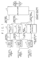
- Fig. 1 is a block diagram showing a structure of a data transmission system using at cellular phones of the present invention.
- the data transmission system using at cellular phones of the present invention consists of a video data input terminal 11, an audio data input terminal 12, a video data encoder 13, an audio data encoder 14, video data storage 15, audio data storage 16, an audio signal detector 17, a multiplexing controller 18, a multiplexer 19, and a data output terminal 20.
- the video data encoder 13 encodes video data inputted from the video data input terminal 11.
- the video data storage 15 stores video data encoded at the video data encoder 13.
- the audio data encoder 14 encodes audio data inputted from the audio data input terminal 12.
- the audio data storage 16 stores audio data encoded at the audio data encoder 14.
- the audio signal detector 17 always measures electric power of audio signals inputted from the audio data input terminal 12 and calculates their audio levels in the passage of time. And further the audio signal detector 17 outputs an audio detected signal 1e to the multiplexing controller 18 and a data write control signal 1d to the video data encoder 13 and the audio data encoder 14, based on the changes of the calculated audio levels in the passage of time and an audio input switch signal 1j.
- the multiplexing controller 18 is controlled by the audio signal detector 17 and controls so that output data from the video data storage 15 and the audio data storage 16 are smoothed and also controls the multiplexer 19.
- the multiplexer 19 receives a data multiplexing control signal 1i from the multiplexing controller 18, and multiplexes smoothed video data If from the video data storage 15 and smoothed audio data 1g from the audio data storage 16, and outputs multiplexed data to the data output terminal 20. And the data output terminal 20 outputs output data 1a.
- Video data inputted from the video data input terminal 11 are encoded to digital data having a designated bit number at the video data encoder 13, and encoded video data 1b are outputted.
- audio data inputted from the audio data input terminal 12 are encoded to digital data having a designated bit number at the audio data encoder 14, and encoded audio data 1c are outputted.
- the audio data inputted from the audio data input terminal 12 are also inputted to the audio signal detector 17 as audio signals.
- the audio signal detector 17 always measures electric power of the audio signals inputted from the audio data input terminal 12.
- the audio signal detector 17 outputs a data write control signal 1d, which instructs the video data encoder 13 and the audio data encoder 14 to write the encoded video data 1b in the video data storage 15 and the encoded audio data 1c in the audio data storage 16. And also the audio signal detector 17 outputs an audio detected signal 1e to the multiplexing controller 18, based on the changes of the audio levels in the passage of time and an audio input switch signal 1j.
- the multiplexing controller 18 outputs a data read control signal 1h to the video data storage 15 and the audio data storage 16 based on the audio detected signal 1e from the audio signal detector 17.
- the video data storage 15 outputs smoothed video data If to the multiplexer 19 based on the data read control signal 1h.
- the audio data storage 16 outputs smoothed audio data 1g to the multiplexer 19 based on the data read control signal 1h.
- the multiplexing controller 18 outputs a data multiplexing control signal 1i to the multiplexer 19 that controls whether data to be multiplexed are the video data and/or the audio data.
- the multiplexer 19 selects the video data and/or the audio data to be transmitted based on the data multiplexing control signal 1i from the multiplexing controller 18, and generates frames and multiplexes the selected data, and outputs multiplexed data to the data output terminal 20.
- the data output terminal 20 outputs output data 1a.
- FIG. 2 is a flowchart showing an output data controlling method at the audio signal detector 17 at the embodiment of the data transmission system using at cellular phones of the present invention.
- Fig. 3 is a diagram showing a waveform of audio input signals 22 and a relation among an audio input switch signal 21 ( 1j ), the audio input signals 22, an audio detected signal 23 ( 1e ), a framing signal 24, and output data 25 ( 1a ) at the embodiment of the data transmission system using at cellular phones of the present invention.
- the step number is the number shown in Fig.2.
- the audio signal detector 17 receives audio input signals 22 from the audio data input terminal 12 (step A1). Electric power of the audio input signals 22 (shown in Fig. 3 (b)) is always measured at the audio signal detector 17 and their audio levels are calculated.
- an audio input switch signal 21 ( 1j ) (shown in Fig. 3 (a)) is judged to be ON (H level) or OFF (L level) (step A2).
- the state S is made to be S 0 signifying that the audio data are not transmitted (step A3).
- the output data is only video data.
- step A4 when the audio input switch signal 21 ( 1j ) is switched to ON from OFF (step A2, SW:ON), it is judged whether the current state S is S 1 or not (step A4), in this, the state S 1 signifies the state that the audio data are not transmitted and only the video data are transmitted at the audio input switch signal 21 ( 1j ) is ON.
- the current state S is S1 (YES at the step A4), it is judged whether the calculated audio levels exceeding a designated level Th1, which is a level being recognized as a sound, continued for over a time t1 or not (step A5).
- the state S is still S 1 (step A6).
- the state S 1 it is judged that the audio data were not inputted, and only the video data are transmitted.
- the state S is made to be S 2 (step A10), and the audio data being a low bit rate and the video data are transmitted.
- step A7 it is judged whether the current state S is S 2 or not (step A7).
- step A7 it is judged whether the detected audio levels exceeding a designated level Th2 continued for over a time t2 (step A8).
- step A8 the current state S is made to be S 3 , and only audio data being a high bit rate are transmitted (step A13).
- this judged result is NO at the step A8, when the audio levels not exceeding the designated level Th1 did not continue for over a time t4 (NO at step A9), the state S is still S 2 (step the A10).
- step A9 it is judged that a sound was not detected and the state S is made to be S1 (the step A6).
- step All it is judged whether the current state S is S 3 or not (step All).
- step A11 it is judged whether the audio levels not exceeding the designated level Th2 continued for over a time t3 or not (step A12).
- step A12 the state S is still S 3 (the step A13).
- the state S is made to be S 2 (the step A10).
- the telecommunication control of the video and audio data are executed based on the judged results of the changes of the audio levels, inputted to the audio data input terminal 12, in the passage of time.
- that an audio level exceeds the designated level Th1 or Th2 signifies that the audio level exceeds either upper line or lower line of the designated level Th1 or Th 2 in the upward direction or the downward direction.
- FIG. 3 signals and data at the present invention are explained in more detail.
- ( a ) signifies the audio input switch signal 21 (audio input switch signal 1j in Fig. 1) that is inputted to the audio signal detector 17 shown in Fig. 1
- ( b ) signifies the audio input signals 22 that are inputted to the audio data input terminal 12 shown in Fig. 1 as audio signals
- ( c ) signifies an audio detected signal 23 (the audio detected signal 1e in Fig. 1) that is outputted to the multiplexing controller 18 from the audio signal detector 17 shown in Fig. 1.
- ( d ) signifies a framing signal 24 that is generated at the multiplexer 19 shown in Fig.
- the ( e ) is output data 25 (output data 1a shown in Fig. 1)
- ( f) signifies output data at the time when the state S is S 0 and S 1
- ( g ) signifies output data at the time when the state S is S 2
- ( h ) signifies output data at the time when the state S is S 3 .
- Fig. 3 shows operation and output data at the time when the audio input switch signal 21 and the audio input signals 22 shown in ( a ) and ( b ) are inputted to the audio signal detector 17 shown in Fig. 1.
- the audio input signals 22 ( b ) are inputted from the audio data input terminal 12.
- the audio input switch signal 21 ( 1j ) is OFF (L level)
- the state of the audio detected signal 23 ( 1e ) is S 0 .
- only the encoded video data 1b from the video data encoder 13 are written in the video data storage 15 by the data write control signal 1d from the audio signal detector 17. Writing operation of the encoded audio data 1c to the audio data storage 16 from the audio data encoder 14 is stopped.
- the multiplexing controller 18 makes the video data storage 15 read out the smoothed video data If to the multiplexer 19 by using the data read control signal 1h based on the audio detected signal 1e, and also outputs the data multiplexing control signal 1i to the multiplexer 19.
- the multiplexer 19 generates the framing signal 24 ( d ) that adds a video and/or audio identification signal to the header of the data and generates frames and outputs the video data with frames by using the data multiplexing control signal 1i to the data output terminal 20.
- the data output terminal 20 outputs the output data 25 ( 1a ).
- the audio signal detector 17 detects audio levels of the audio input signals 22.
- the audio detected signal 23 ( 1e ) is in the state S 1 , at the same as the state So mentioned above, the encoded video data 1b from the video data encoder 13 are written in the video data storage 15 by the data write control signal 1d from the audio signal detector 17. Writing operation of the encoded audio data 1c to the audio data storage 16 from the audio data encoder 14 is stopped.
- the multiplexing controller 18 makes the video data storage 15 read out the smoothed video data If to the multiplexer 19 by using the data read control signal 1h based on the audio detected signal 1e, and also outputs the data multiplexing control signal 1i to the multiplexer 19.
- the multiplexer 19 generates the framing signal 24 ( d ) that adds the video and/or audio identification signal to the header of the data and generates frames and outputs the video data with frames by using the data multiplexing control signal 1i to the data output terminal 20.
- the data output terminal 20 outputs the output data 25 ( 1a ).
- the output data are only video data as shown in ( f) in Fig. 3.
- the encoded video data 1b from the video data encoder 13 are written in the video data storage 15 by the data write control signal 1d from the audio signal detector 17.
- the encoded audio data 1c being a low bit rate from the audio data encoder 14 are written in the audio data storage 16 by the data write control signal 1d from the audio signal detector 17.
- the multiplexing controller 18 makes the video data storage 15 read out the smoothed video data 1f and also makes the audio data storage 16 read out the smoothed audio data 1g to the multiplexer 19 by using the data read control signal 1h based on the audio detected signal 1e, and also outputs the data multiplexing control signal 1i to the multiplexer 19.
- the multiplexer 19 generates the framing signal 24 ( d ) that adds the video and/or audio identification signal to the header of the data and generates frames and outputs the video and audio data with frames by using the data multiplexing control signal 1i to the data output terminal 20. And the data output terminal 20 outputs the output data 25 ( 1a). At the case that the state S is only S 2 , the output data are shown in Fig. 3 ( g ).
- the encoded audio data 1c being a high bit rate from the audio data encoder 14 are written in the audio data storage 16 by the data write control signal 1d from the audio signal detector 17. And writing the encoded video data 1b to the video data storage 15 from the video data encoder 13 is stopped.
- the multiplexing controller 18 makes the audio data storage 16 read out the smoothed audio data 1g to the multiplexer 19 by using the data read control signal 1h based on the audio detected signal 1e, and also outputs the data multiplexing control signal 1i to the multiplexer 19.
- the multiplexer 19 generates the framing signal 24 ( d ) that adds the video and/or audio identification signal to the header of the data and generates frames and outputs the audio data with frames by using the data multiplexing control signal 1i to the data output terminal 20. And the data output terminal 20 outputs the output data 25 ( 1a ). At the case that the state S is only S 3 , the output data are shown in Fig. 3 ( h ).
- the output data are shown in the cases that the mentioned above state S is S 0 , S 1 , S 2 , or S 3 .
- an audio signal detector is provided. And when the audio signal detector detects audio signals exceeding a designated audio level for over a designated time while video data are transmitting, transmission of audio data starts by a low bit rate, and multiplex telecommunication of the video data and the audio data is executed. With this, it is avoided that the transmission of the video data is stopped by a single sound. And at this state, when different audio signals exceeding another designated audio level are detected for over another designated time, the transmission of the audio data is executed by a high bit rate and the transmission of the video data is stopped, with this, the audio quality is improved.
- the telecommunication control of the video data and the audio data to be transmitted is executed based on the changes of audio levels of inputted audio signals in the passage of time. Therefore, transmission lines in an existing transmission capacity can be used efficiently, and the quality of video and audio data to be transmitted can be improved.
Landscapes
- Engineering & Computer Science (AREA)
- Multimedia (AREA)
- Signal Processing (AREA)
- Computer Networks & Wireless Communication (AREA)
- General Engineering & Computer Science (AREA)
- Mobile Radio Communication Systems (AREA)
- Time-Division Multiplex Systems (AREA)
- Two-Way Televisions, Distribution Of Moving Picture Or The Like (AREA)
- Telephonic Communication Services (AREA)
Abstract
Description
Claims (6)
- A data transmission system using at cellular phones, which provides a video data encoder that encodes inputted video data, an audio data encoder that encodes inputted audio data, video data storage that stores encoded video data outputted from said video data encoder, audio data storage that stores encoded audio data outputted from said audio data encoder, and a multiplexer that multiplexes smoothed video data outputted from said video data storage and smoothed audio data outputted from said audio data storage, and transmits multiplexed video and audio data, comprising:an audio signal detector which audio signals of said inputted audio data and an audio input switch signal are inputted to; anda multiplexing controller, wherein:said audio signal detector measures audio levels of said inputted audio signals and generates a data write control signal for controlling said video data encoder and said audio data encoder and also generates an audio detected signal for controlling said multiplexing controller; andsaid multiplexing controller generates a data read control signal for controlling said video data storage and said audio data storage, and also generates a data multiplexing control signal for controlling said multiplexer.
- A data transmission system using at cellular phones in accordance with claim 1, wherein:
said audio signal detector measures changes of said audio levels of said inputted audio signals in the passage of time. - A data transmission system using at cellular phones in accordance with claim 2, wherein:
said audio signal detector judges whether said audio levels exceeded predetermined one or more levels or not. - A data transmission system using at cellular phones in accordance with claim 3, wherein:
said audio signal detector measures one or more periods that said audio levels exceeded said predetermined one or more levels. - A system in accordance with claim 1, 2, 3 or 4, wherein:
said audio signal detector and said multiplexing controller work to transmit only said inputted video data regardless of said audio levels of said inputted audio signals, at the case that said audio input switch signal is OFF. - A system in accordance with claim 1, 2, 3, 4 or 5, wherein:
said audio signal detector and said multiplexing controller, at the case that said audio input switch signal is ON, work to control said encoded video data and a transmission bit rate of said encoded audio data in plural cases whether said audio levels of said inputted audio signals exceeded one or more predetermined levels and continued for one or more predetermined periods.
Applications Claiming Priority (2)
| Application Number | Priority Date | Filing Date | Title |
|---|---|---|---|
| JP2000088256A JP2001274923A (en) | 2000-03-28 | 2000-03-28 | Portable telephone transmission system |
| JP2000088256 | 2000-03-28 |
Publications (2)
| Publication Number | Publication Date |
|---|---|
| EP1143741A2 true EP1143741A2 (en) | 2001-10-10 |
| EP1143741A3 EP1143741A3 (en) | 2003-04-16 |
Family
ID=18604153
Family Applications (1)
| Application Number | Title | Priority Date | Filing Date |
|---|---|---|---|
| EP01107451A Withdrawn EP1143741A3 (en) | 2000-03-28 | 2001-03-27 | Data transmission system using at cellular phones |
Country Status (3)
| Country | Link |
|---|---|
| US (1) | US7035296B2 (en) |
| EP (1) | EP1143741A3 (en) |
| JP (1) | JP2001274923A (en) |
Families Citing this family (4)
| Publication number | Priority date | Publication date | Assignee | Title |
|---|---|---|---|---|
| US7404001B2 (en) * | 2002-03-27 | 2008-07-22 | Ericsson Ab | Videophone and method for a video call |
| US7003040B2 (en) * | 2002-09-24 | 2006-02-21 | Lg Electronics Inc. | System and method for multiplexing media information over a network using reduced communications resources and prior knowledge/experience of a called or calling party |
| JP4831351B2 (en) * | 2007-02-01 | 2011-12-07 | 日本電気株式会社 | Audiovisual bandwidth control system and audiovisual bandwidth control method |
| CN104661081B (en) * | 2015-03-18 | 2018-07-03 | 飞狐信息技术(天津)有限公司 | A kind of audio data transmission method and device |
Family Cites Families (27)
| Publication number | Priority date | Publication date | Assignee | Title |
|---|---|---|---|---|
| US4922520A (en) * | 1986-12-31 | 1990-05-01 | M. A. Kempner, Inc. | Automatic telephone polling system |
| US5408686A (en) * | 1991-02-19 | 1995-04-18 | Mankovitz; Roy J. | Apparatus and methods for music and lyrics broadcasting |
| US5134651A (en) * | 1991-04-18 | 1992-07-28 | Codecom Rural Communications, Inc. | Method and apparatus for providing answer supervision and an autonomous pay telephone incorporating the same |
| JPH04323938A (en) * | 1991-04-23 | 1992-11-13 | Toshiba Corp | Hand-free circuit |
| JP3320086B2 (en) | 1991-12-11 | 2002-09-03 | キヤノン株式会社 | Multimedia communication method |
| US5319702A (en) * | 1992-07-29 | 1994-06-07 | Tele-Matic Corporation | Method and apparatus for detecting and responding to hook flash events occurring on a remote telephone |
| JP3211398B2 (en) | 1992-09-04 | 2001-09-25 | 松下電器産業株式会社 | Speech detection device for video conference |
| JPH06261017A (en) * | 1993-03-08 | 1994-09-16 | Matsushita Electric Ind Co Ltd | Multi-media communications equipment |
| US5511054A (en) * | 1993-03-31 | 1996-04-23 | Sony Corporation | Apparatus and method for multiplexing encoded data signals and recording medium having multiplexed signals recorded thereon |
| JP3546889B2 (en) * | 1993-08-24 | 2004-07-28 | ソニー株式会社 | Multiplexing transmission method and apparatus |
| JPH07154362A (en) | 1993-12-01 | 1995-06-16 | Matsushita Electric Ind Co Ltd | Time division multiplex communication system |
| JPH07202820A (en) * | 1993-12-28 | 1995-08-04 | Matsushita Electric Ind Co Ltd | Bit rate control system |
| JPH0870363A (en) | 1994-08-30 | 1996-03-12 | Murata Mach Ltd | Image and sound integration transmitter and receiver |
| JPH0883480A (en) | 1994-09-13 | 1996-03-26 | Toshiba Corp | Recording medium playback device |
| JPH08149430A (en) | 1994-11-17 | 1996-06-07 | Canon Inc | Communication terminal |
| JPH09130313A (en) | 1995-10-31 | 1997-05-16 | Sharp Corp | Multimedia wireless communication system |
| JP3727431B2 (en) * | 1995-12-08 | 2005-12-14 | シャープ株式会社 | Transmitter, telephone using it |
| JPH09233231A (en) * | 1996-02-20 | 1997-09-05 | Internatl Business Mach Corp <Ibm> | Data transmission method and device therefor |
| KR100242336B1 (en) * | 1996-10-31 | 2000-02-01 | 윤종용 | Voice Scaling Circuit Using Pulse Width Modulation Signal |
| WO1998032252A1 (en) * | 1997-01-21 | 1998-07-23 | Sony Corporation | Coded signal transmission method and device |
| JP4341078B2 (en) | 1997-02-14 | 2009-10-07 | 株式会社デンソー | Encoding device for moving picture information |
| US6588014B1 (en) * | 1997-09-26 | 2003-07-01 | Matsushita Electric Industrial Co., Ltd. | System and method for digital communication |
| JPH11150711A (en) | 1997-11-17 | 1999-06-02 | Nec Corp | Video conference data transferring device |
| EP0994427A4 (en) * | 1998-05-06 | 2004-03-24 | Matsushita Electric Industrial Co Ltd | METHOD AND SYSTEM FOR TRANSMITTING / RECEIVING DIGITAL DATA |
| US6483543B1 (en) * | 1998-07-27 | 2002-11-19 | Cisco Technology, Inc. | System and method for transcoding multiple channels of compressed video streams using a self-contained data unit |
| US6181693B1 (en) * | 1998-10-08 | 2001-01-30 | High Speed Video, L.L.C. | High speed video transmission over telephone lines |
| US6754241B1 (en) * | 1999-01-06 | 2004-06-22 | Sarnoff Corporation | Computer system for statistical multiplexing of bitstreams |
-
2000
- 2000-03-28 JP JP2000088256A patent/JP2001274923A/en active Pending
-
2001
- 2001-03-27 US US09/817,157 patent/US7035296B2/en not_active Expired - Fee Related
- 2001-03-27 EP EP01107451A patent/EP1143741A3/en not_active Withdrawn
Also Published As
| Publication number | Publication date |
|---|---|
| US7035296B2 (en) | 2006-04-25 |
| US20010026562A1 (en) | 2001-10-04 |
| EP1143741A3 (en) | 2003-04-16 |
| JP2001274923A (en) | 2001-10-05 |
Similar Documents
| Publication | Publication Date | Title |
|---|---|---|
| US6128374A (en) | Method and apparatus for transmitting coded audio signals through a transmission channel with limited bandwidth | |
| US4630257A (en) | Duplex speech transmission method and a system therefor | |
| WO1996032805A9 (en) | Method and apparatus for transmitting coded audio signals through a transmission channel with limited bandwidth | |
| JP3082825B2 (en) | Communication device | |
| EP1143741A2 (en) | Data transmission system using at cellular phones | |
| KR100382393B1 (en) | Circuit and method for recording and reproducing speech and other sounds in digital mobile devices | |
| US20070060195A1 (en) | Communication apparatus for playing sound signals | |
| EP1065808A2 (en) | Digital radio | |
| CN1084103C (en) | Telephone apparatus with recording function | |
| JP2006074359A (en) | Transmission reception system of audio data in teleconference system and control method | |
| JPS59231A (en) | Sensitivity controlling system | |
| EP2424159A1 (en) | Information transmission apparatus, information transmission method, and computer readable medium | |
| EP0676868B1 (en) | Audio signal transmission apparatus | |
| US20050272407A1 (en) | Mobile telephone | |
| US6473497B1 (en) | Digital telephone set | |
| JPH05111017A (en) | Video telephone set | |
| JP3292613B2 (en) | Single-wave simultaneous transmission / reception radio | |
| JP3587713B2 (en) | Adaptive differential pulse code modulation system and transmitter and receiver therefor | |
| JPH06296277A (en) | Video telephone system | |
| JPH07131774A (en) | Video conferencing equipment | |
| JP4227875B2 (en) | Call recording adapter device | |
| JP2908335B2 (en) | Voice / digital data multiplex transmission method for information processing equipment. | |
| JPH06237443A (en) | Voice/moving picture communication system | |
| JP3491320B2 (en) | Communication device | |
| JPH11331434A (en) | Voice conference terminal, multipoint voice conference controller, and program recording medium for voice conference terminal |
Legal Events
| Date | Code | Title | Description |
|---|---|---|---|
| PUAI | Public reference made under article 153(3) epc to a published international application that has entered the european phase |
Free format text: ORIGINAL CODE: 0009012 |
|
| AK | Designated contracting states |
Kind code of ref document: A2 Designated state(s): AT BE CH CY DE DK ES FI FR GB GR IE IT LI LU MC NL PT SE TR |
|
| AX | Request for extension of the european patent |
Free format text: AL;LT;LV;MK;RO;SI |
|
| PUAL | Search report despatched |
Free format text: ORIGINAL CODE: 0009013 |
|
| AK | Designated contracting states |
Designated state(s): AT BE CH CY DE DK ES FI FR GB GR IE IT LI LU MC NL PT SE TR |
|
| AX | Request for extension of the european patent |
Extension state: AL LT LV MK RO SI |
|
| 17P | Request for examination filed |
Effective date: 20030306 |
|
| AKX | Designation fees paid |
Designated state(s): DE FR GB |
|
| 17Q | First examination report despatched |
Effective date: 20061006 |
|
| STAA | Information on the status of an ep patent application or granted ep patent |
Free format text: STATUS: THE APPLICATION IS DEEMED TO BE WITHDRAWN |
|
| 18D | Application deemed to be withdrawn |
Effective date: 20070217 |