The present invention relates generally to a method
and an apparatus for measurement of communication quality
in a mobile communication system using a CDMA cellular
system. More particularly, the invention relates to a
method and an apparatus for measuring desired signal power,
interference signal power, SIR and propagation paths
between transmitter and receiver, as communication
quality. Also the invention relates to a method and a
system for detection of synchronization suitable for
measuring communication quality using channels spread by
relatively long known spreading code constantly
transmitted by installed base stations.
In CDMA cellular system, it is required to detect
a synchronization chip timing of a channel to measure,
namely a reception chip timing in conventional measurement
of communication quality (propagation characteristics).
It should be noted that the reception chip timing is
premised to match with a position of a path between
transmitter and receiver in time effective for
communication. Next, for setting a correlation detector
called as finger for the reception chip timing for deriving
a received signal vector in the reception chip timing from
a correlation value.
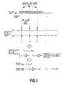
Fig. 1 shows a process for deriving a desired signal
power and an interference signal power. The signal vector
set forth above is a sum of the desired signal and the
interference signal. Therefore, a received signal vector
obtained within a certain given period (normally about 3
to 5 symbols) is summed and averaged to take obtained vector
as a desired signal vector. The desired signal power is
derived as a power of the desired signal vector. The
interference signal vector is derived from a variance of
the received signal vector with taking the desired signal
vector as reference. Here, the chip length to be used in
correlation is referred to as one symbol.
Effective paths between transmitter and receiver
presents in about three to five paths in urban area in
general (here, chip rate is about 4 Mcps). Accordingly,
in order to obtain the desired signal power, the
interference signal power and SIR for all of the effective
paths, corresponding number of fingers are required to be
not effective. On the other hand, vector averaging is
included during process of measurement, it is essential
that the symbol to be used for averaging is "a symbol which
can be regarded to have the same phase of the desired signal
vector". Normally, the symbol continuous in time is used.
However, the condition is different when a transmit
diversity is applied to the channel to be measured.
For example, when the channel to be measured is taken
as a common pilot channel when the transmit diversity is
applied, at first, the received signal vector after
correlation detection is added and subtracted by preceding
and following symbols to separate into received signal
vector per each transmission antenna. Next, the desired
signal power and the interference signal power are derived
by performing the foregoing calculation per each received
signal vector. By combining the desired signal power and
the interference signal power obtained for each
transmission antenna, the desired signal power and the
interference signal power upon use of the transmit
diversity is derived.
During this process, the received signal vector for
each transmission antenna can be obtained only at every
two symbol period. Accordingly, number of samples to be
used in averaging, namely number of received signal
vectors, becomes smaller in comparison with the case where
the transmit diversity is not applied, to degrade
measurement precision for each transmission antenna.
When number of samples is set to be the same number as that
when the transmit diversity is not applied, phase
variation of the desired signal vector due to fading
becomes not ignorable. Naturally, the measurement
precision for each transmission antenna is lowered, the
measurement precision after final combination is also
lowered.
On the other hand, when a measurement system is
installed on a mobile measurement vehicle for measuring
communication quality while moving, the path position
between transmitter and receiver is moved per each path
according to movement of the mobile measurement vehicle.
Accordingly, upon measuring, detection of reception chip
timing has to be constantly performed and position of the
finger has to be updated. When updating speed is low
relative to movement of the path, the reception chip timing
and path position can be offset. Therefore, obtained
measured value cannot be correct.
As a method for detection of synchronization chip
timing, namely a method that the mobile equipment detects
of synchronization with the connecting base station at a
preceding stage to perform measurement of communication
quality, so-called 3-step cell search method is used in
a wide band CDMA (hereinafter referred to as W-CDMA)
cellular system. More particularly, so-called 3-step
cell search method is a method performing detection of
synchronization using three channels of PSCH (Primary
Synchronization CHannel), SSCH (Secondary
Synchronization CHannel), CPICH (Common Pilot CHannel)
transmitted from the base station. A cause why three
channels are used by the 3-step cell search method is that
the code of the channel transmitted from the base station
(scrambling code) is unknown.
However, in measurement system or the like, in which
the base station as object for measurement (objective
scrambling code), the 3-step cell search method cannot be
effective synchronization detection method. For example,
when CPICH transmitted from the base station is used as
channel to be measured, detection of synchronization may
be performed by using only scrambling code, in which CPICH
of the base station as object for measurement is spread.
On the other hand, when it is not necessary to perform
communication between the base station and the mobile
equipment immediately after detection of synchronization
and when the synchronization chip timing may be determined
with a certain range, complete synchronization detection
is not required. Furthermore, it is possible to perform
measurement of a service area by installing pseudo base
station in advance of actual installation of the base
station. In such case, it is not efficient to transmit
three channels corresponding PSCH, SSCH and CPICH by the
pseudo base station for measurement.
By the conventional method, for measuring
communication quality (propagation characteristics) at
high precision, correlation detectors called as fingers
are provided in number corresponding to number of the paths,
and installation position of each finger (reception chip
timing) has to be certainly matched with the position of
the path. Also, it is not efficient for constraint
condition for number of samples and sampling interval upon
deriving the desired signal power, the interference signal
power in each reception chip timing.
On the other hand, it is not efficient in that number
of samples and sampling interval are different depending
upon whether transmit diversity is applied or not.
Furthermore, in the conventional method, upon
performing detection of synchronization of the channel to
be measured, channel other than the channel to be measured
is required to be inefficient.
The present invention has been worked out the
problems set forth above. It is therefore an object of
the present invention is to provide a communication
quality measuring method and an apparatus for measurement
of communication quality (propagation characteristics)
with high precision and high efficiency by taking all chip
timing in a range set at a reception chip timing detected
in a preliminary step of measurement, and generating two
time series having several period of time difference from
a received signal vector of the same chip timing obtained
within a certain given period.
Another object of the present invention is to provide
a synchronization detecting method and apparatus which can
perform detection of synchronization for measurement at
high speed, high precision and high reliability.
A further object of the present invention to provide
a synchronization detecting method and apparatus which can
perform detection of synchronization for measurement at
high speed, high precision and high reliability while
transmit diversity is applied.
In order to accomplish the above-mentioned object,
according to the 1st invention, a communication quality
measuring method in CDMA cellular system detecting a
reception chip timing of a channel to be measured and
measuring communication quality, comprises: time series
generating step of generating two series of data consisted
of a time series data of a detected value and a time series
data delayed for one, two or more periods, with respect
to the reception chip timing where the detected value
becomes the same; matrix calculation step of deriving
covariant matrix of the two series data generated in the
time series generating step; first power calculating step
of deriving a desired signal power and an interference
signal power in the reception chip timing from eigenvalues
of the covariant matrix; and SIR calculating step deriving
a SIR at the reception chip timing from the desired signal
power and the interference signal power. With this method,
the desired signal power, the interference signal power
and SIR can be measured without restriction of sample
number and sampling interval in series.
According to the 2nd invention, a communication
quality measuring method in CDMA cellular system detecting
a reception chip timing of a channel to be measured and
measuring communication quality, comprising: time series
generating step of generating two series of data consisted
of a time series data of a detected value and a time series
data delayed for one, two or more periods, with respect
to the reception chip timing where the detected value
becomes the same; adding step of deriving an add vector
from addition of received signal vector between two points
close in reception timing when the two series data
generated in the time series generating step becomes a
particular correlation value; subtracting step of
deriving a difference vector from a difference of received
signal vectors between two points close in reception
timing; second power calculation step of deriving a
desired signal power and an interference signal power-by
averaging the add vectors and the difference vectors; and
SIR calculating step deriving a SIR at the reception chip
timing from the desired signal power and the interference
signal power. With this method, the desired signal power,
the interference signal power and SIR can be simply and
precisely measured without restriction of sample number
and sampling interval in series.
According to the 3rd invention, in the 1st and 2nd
invention, a communication quality measuring method in
CDMA cellular system further comprises third power
calculation step of deriving an averaged desired signal
power and an averaged interference signal power by
performing averaging in a given period from the desired
signal power and the interference signal power obtained
in a first power calculation step and the second power
calculation step, and in the SIR calculation step, the SIR
is derived from the averaged desired signal power and the
averaged interference signal power.
According to the 4th invention, in the 1st and 2nd
invention, when the channel to be measured is plural and
only one correlation detector is useful, correlation
detection of a plurality of channels are performed in time
division for generating two series generated in the same
reception chip timing per channel.
According to the 5th invention, in the 4th invention,
a communication quality measuring method in CDMA cellular
system further comprises fourth power calculation step of
deriving an averaged desired signal power and an averaged
interference signal power by averaging a given period from
the desired signal power and the interference signal power
obtained in the first power calculation step and a second
power calculation step, and in the SIR calculation step,
the SIR is derived from the averaged desired signal power
and the averaged interference signal power.
According to the 6th invention, in the 3rd invention,
when the channel to be measured is plural and only one
correlation detector is useful, in the third power
calculating step, the averaged desired signal power and
the average interference signal power are derived in time
division, and in the SIR calculation step, the SIR of a
plurality of channels are derived in time division.
According to the 7th invention, in the 1st and 2nd
invention, the communication quality measuring method
in CDMA cellular system further comprises path detection
step of deriving paths of transmitter and receiver to be
effective for communication from a value of the SIR
obtained in the SIR calculation step. With this method,
judgment whether the measured reception chip timing from
the measured based on the value of measured SIR matches
the position of the path effective for communication, or
not, is facilitated. On the other hand, when all chip
timing in the measurement window including the detected
reception chip timing are taken as object for measurement,
effective path can be derived from the value of SIR of each
chip.
According to the 8th invention, a communication
quality measuring apparatus in CDMA cellular system
detecting a reception chip timing of a channel to be
measured and measuring communication quality, comprising:
time series generating means for generating two series of
data consisted of a time series data of a detected value
and a time series data delayed for one, two or more periods,
with respect to the reception chip timing where the
detected value becomes the same; matrix calculation means
for deriving covariant matrix of the two series data
generated in the time series generating means; first power
calculating means for deriving a desired signal power and
an interference signal power in the reception chip timing
from eigenvalues of the covariant matrix; and SIR
calculating means deriving a SIR at the reception chip
timing from the desired signal power and the interference
signal power. With this method, the desired signal power,
the interference signal power and SIR can be measured
without restriction of sample number and sampling interval
in series.
According to the 9th invention, a communication
quality measuring apparatus in CDMA cellular system
detecting a reception chip timing of a channel to be
measured and measuring communication quality, comprises:
time series generating means for generating two series of
data consisted of a time series data of a detected value
and a time series data delayed for one, two or more periods,
with respect to the reception chip timing where the
detected value becomes the same; adding means for deriving
an add vector from addition of received signal vector
between two points close in reception timing when the two
series data generated in the time series generating means
becomes a particular correlation value; subtracting means
for deriving a difference vector from a difference of
received signal vectors between two points close in
reception timing; second power calculation means for
deriving a desired signal power and an interference signal
power by averaging the add vectors and the difference
vectors; and SIR calculating means deriving a SIR at the
reception chip timing from the desired signal power and
the interference signal power. With this method, the
desired signal power, the interference signal power and
SIR can be simply and precisely measured without
restriction of sample number and sampling interval in
series.
According to the 10th invention, in 8th or 9th
invention, the communication quality measuring apparatus
in CDMA cellular system further comprises third power
calculation means for deriving an averaged desired signal
power and an averaged interference signal power by
performing averaging in a given period from the desired
signal power and the interference signal power obtained
in the first power calculation means and a second power
calculation means.
According to the 11th invention, in 8th or 9th
invention, when the channel to be measured is plural and
only one correlation detector is useful, the time series
generating means derives the averaged desired signal power
and the average interference signal power in time division,
and the SIR calculation means derives the SIR of a plurality
of channels in time division.
According to the 12th invention, in the 11th
invention, the communication quality measuring apparatus
in CDMA cellular system further comprises fourth power
calculation means for deriving an averaged desired signal
power and an averaged interference signal power by
averaging a given period from the desired signal power and
the interference signal power obtained in the first power
calculation means and a second power calculation means.
According to the 13th invention, in the 10th
invention, the communication quality measuring apparatus
in CDMA cellular system comprises third power calculation
means for deriving an averaged desired signal power and
an averaged interference signal power by performing
averaging in a given period from the desired signal power
and the interference signal power obtained in a first power
calculation means and the second power calculation means.
According to the 14th invention, the communication
quality measuring apparatus in CDMA cellular system
further comprises path detection means for deriving paths
between transmitter and receiver to be effective for
communication from a value of the SIR obtained in the SIR
calculation means. With this construction, judgment can
be done easily whether the reception chip timing measured
from the value of the measured SIR matches with the position
of the path effective for communication or not. Also, when
all chip timing in the measurement window including the
detected reception chip timing is taken as object for
measurement, effective paths can be derived from the value
of SIR of each chip.
According to the 15th invention, a communication
quality measuring method detecting reception chip timing
of channel to be measured repeatedly transmitted a
transmission symbol series of a known pattern and
performing measurement of communication quality,
comprises: correlation detection step of performing
correlation detection of received signal using a code
series spreading the channel to be measured; delay step
of delaying one of received series detected in the
correlation detection step for one, two or more symbol
period within a range where mutual correlation between
transmission symbol series is 1 and influence of a
propagation path can be regarded as the same; vector
calculation step of calculating difference vector and add
vector from difference value and add value of respective
received signal vectors of the same reception chip timing
in the other received series detected by the correlation
detection step and the received series provided delay in
the delay step; and communication quality calculation step
of calculating a desired signal power, an interference
signal power and SIR from the difference vector and the
add vector calculated in the vector calculation step.
With this method, by providing a time difference within
a range where the correlation between the transmission
symbol series is 1 and influence of the propagation path
can be regarded as the same, the desired signal power, the
interference signal power and SIR can be simply and
precisely measured.
According to the 16th invention, a communication
quality measuring method detecting reception chip timing
of channel to be measured repeatedly transmitted
transmission symbol series of respectively different
known pattern using common spreading code from different
antennas upon use of transmit diversity and performing
measurement of communication quality, comprises:
correlation detection step of performing correlation
detection of received signal using a code series spreading
the channel to be measured; delay step of delaying one of
received series detected in the correlation detection step
for one, two or more symbol period within a range where
mutual correlation between transmission symbol series in
the different antennas is 1 and influence of a propagation
path can be regarded as the same; vector calculation step
of calculating difference vector and add vector from
difference value and add value of respective received
signal vectors of the same reception chip timing in the
other received series detected by the correlation
detection step and the received series provided delay in
the delay step; and communication quality calculation step
of calculating a desired signal power, an interference
signal power and SIR from the difference vector and the
add vector calculated in the vector calculation step.
With this method, the desired signal power, the
interference signal power and SIR of the channel to be
measured and applying the transmit diversity, can be
measured precisely and easily.
According to the 17th invention, in the 15th
invention, the communication quality measuring apparatus
further comprises vector selection step of selecting only
result of calculation at the same reception chip timing
of received symbol matching respective transmission
symbols of the different antenna among difference vector
and add vector calculated in the vector calculation step
when a mutual correlation between transmission symbol
series is smaller than one.
According to the 18th invention, in the 16th
invention, the communication quality measuring apparatus
further comprises vector selection step of selecting only
result of calculation at the same reception chip timing
of received symbol matching respective transmission
symbols of the different antenna among difference vector
and add vector calculated in the vector calculation step
when a mutual correlation between transmission symbol
series in the different antenna is smaller than one.
According to the 19th invention, a communication
quality measuring apparatus detecting reception chip
timing of channel to be measured repeatedly transmitted
a transmission symbol series of a known pattern and
performing measurement of communication quality,
comprises: correlation detection means for performing
correlation detection of received signal using a code
series spreading the channel to be measured; delay means
for delaying one of received series detected in the
correlation detection step for one, two or more symbol
period within a range where mutual correlation between
transmission symbol series is 1 and influence of a
propagation path can be regarded as the same; vector
calculation means for calculating difference vector and
add vector from difference value and add value of
respective received signal vectors of the same reception
chip timing in the other received series detected by the
correlation detection step and the received series
provided delay in the delay step; and communication
quality calculation means for calculating a desired signal
power, an interference signal power and SIR from the
difference vector and the add vector calculated in the
vector calculation step. With this method, by providing
a time difference within a range where the correlation
between the transmission symbol series is 1 and influence
of the propagation path can be regarded as the same, the
desired signal power, the interference signal power and
SIR can be simply and precisely measured.
According to the 20th invention, a communication
quality measuring apparatus detecting reception chip
timing of channel to be measured repeatedly transmitted
transmission symbol series of respectively different
known pattern using common spreading code from different
antennas upon use of transmit diversity and performing
measurement of communication quality, comprises:
correlation detection means for performing correlation
detection of received signal using a code series spreading
the channel to be measured; delay means for delaying one
of received series detected in the correlation detection
step for one, two or more symbol period within a range where
mutual correlation between transmission symbol series in
the different antennas is 1 and influence of a propagation
path can be regarded as the same; vector calculation means
for calculating difference vector and add vector from
difference value and add value of respective received
signal vectors of the same reception chip timing in the
other received series detected by the correlation
detection step and the received series provided delay in
the delay step; and communication calculation quality
means for calculating a desired signal power, an
interference signal power and SIR from the difference
vector and the add vector calculated in the vector
calculation step. With this method, the desired signal
power, the interference signal power and SIR can be
measured more precisely. With this method, the desired
signal power, the interference signal power and SIR of the
channel to be measured and applying the transmit diversity,
can be measured precisely and easily.
According to the 21st invention, in the 19th
invention, the communication quality measuring apparatus
further comprises vector selection means for selecting
only result of calculation at the same reception chip
timing of received symbol matching respective
transmission symbols of the different antenna among
difference vector and add vector calculated in the vector
calculation step when a mutual correlation between
transmission symbol series is smaller than one. With this
construction, the desired signal power, the interference
signal power and SIR can be measured more precisely.
According to the 22nd invention, in the 19th
invention, the communication quality measuring apparatus
further comprises vector selection means for selecting
only result of calculation at the same reception chip
timing of received symbol matching respective
transmission symbols of the different antenna among
difference vector and add vector calculated in the vector
calculation step when a mutual correlation between
transmission symbol series in the different antenna is
smaller than one. With this construction, the desired
signal power, the interference signal power and SIR can
be measured more precisely. With this construction, the
desired signal power, the interference signal power and
SIR can be measured more precisely.
According to the 23rd invention, for measuring
communication quality in a mobile receiving station in a
mobile communication system employing a CDMA cellular
system, using channel spread with spreading code and
constantly transmitted from a base station, a
synchronization detecting method in CDMA cellular system
comprises the step of: in the mobile receiving station,
determining a synchronization chip timing of a channel to
be measured by detecting partial correlation value between
spreading code to be measured and a received signal. With
this method, since the partial correlation value is
derived between the spreading code of the channel to be
measured and the received signal, three channels are not
required for synchronization detection.
According to the 24th invention, in the 23rd
invention, a matched filter is used upon detection of the
partial correlation value and a synchronization chip
timing of the channel to be measured is detected by
sequentially rewriting the code in the matched filter.
With this method, synchronization detection using the
partial correlation value can be performed at high speed,
high precision and high reliability.
According to the 25th invention, in the 23rd and 24th
inventions, an averaging period and sampling period are
preliminarily set in advance of performing the
synchronization detection, and the synchronization chip
timing of the channel to be measured is determined on the
basis of a value derived by averaging of detected plurality
of partial correlation values in the averaging period by
detecting the partial detection values per set sampling
period.
According to the 26th invention, in the 25th
invention, upon averaging process of the detected
plurality of partial correlation values, the
synchronization chip timing of the channel to be measured
is determined using an averaged value by preliminarily
calculating the averaged value by power averaging process
or vector averaging process.
According to the 27th invention, in the 26th
invention, the synchronization chip timing of the channel
to be measured is determined by enabling setting of process
of the averaging process for a plurality of times and using
the averaged value derived by a plurality of times of
averaging process by the same or different averaging
method in each process.
According to the 28th invention, the steps of
performing synchronization chip timing detection process
for a plurality of times as defined in any one of 23rd to
27th, and making judgment whether synchronization chip
timing of a channel to be measured is to be determined using
an average value of a plurality of timing value and a
standard deviation value, the synchronization chip timing
of the channel to be measured is determined with providing
a given range, or synchronization detection is to be
performed again. With this method, correctness of the
detected synchronization chip timing can be easily judged.
Also, upon performing measurement of communication
quality using the measurement window, position and width
of the window can be determined.
According to the 29th invention, for measuring
communication quality in a mobile receiving station in a
mobile communication system employing a CDMA cellular
system, using channel spread with spreading code and
constantly transmitted from a base station, a
synchronization detecting device in CDMA cellular system
comprises: the mobile receiving station including means
for determining a synchronization chip timing of a channel
to be measured by detecting partial correlation value
between spreading code to be measured and a received signal.
With this method, since the partial correlation value is
derived between the spreading code of the channel to be
measured and the received signal, three channels are not
required for synchronization detection.
According to the 30th invention, in the 29th
invention, the means includes a matched filter is used upon
detection of the partial correlation value and a
synchronization chip timing of the channel to be measured
is detected by sequentially rewriting the code in the
matched filter. With this construction, synchronization
detection using partial correlation can be performed at
high speed, high precision and high reliability.
According to the 31st invention, the 29th and 30th
inventions, the means preliminarily sets an averaging
period and sampling period in advance of performing the
synchronization detection, and determines the
synchronization chip timing of the channel to be measured
on the basis of a value derived by averaging of detected
plurality of partial correlation values in the averaging
period by detecting the partial detection values per set
sampling period.
According to 32nd invention, in the 31st invention,
upon averaging process of the detected plurality of
partial correlation values, the means determines the
synchronization chip timing of the channel to be measured
using an averaged value by preliminarily calculating the
averaged value by power averaging process or vector
averaging process.
According to the 33rd invention, in the 32nd
invention, the means determines the synchronization chip
timing of the channel to be measured by enabling setting
of process of said averaging process for a plurality of
times and using the averaged value derived by a plurality
of times of averaging process by the same or different
averaging device in each process.
According to the 34th invention, a synchronization
detecting device in CDMA cellular system comprises means
for performing synchronization chip timing detection
process for a plurality of times as defined in any one of
the 29th to 33rd inventions, and making judgment whether
synchronization chip timing of a channel to be measured
is to be determined using an average value of a plurality
of timing value and a standard deviation value, the
synchronization chip timing of the channel to be measured
is determined with providing a given range, or
synchronization detection is to be performed again. With
this method, correctness of the detected synchronization
chip timing can be easily judged. Also, upon performing
measurement of communication quality using the
measurement window, position and width of the window can
be determined.
According to the 35th invention, in a mobile
communication system employing CDMA cellular system using
a common pilot channel constantly transmitted from a base
station in a mobile communication system upon use of
transmit diversity for measuring communication quality in
a mobile station being measured, a synchronization
detecting device comprises: the mobile station
separating received signal vector obtained by correlation
detection of received signal per symbol into received
signal vector per transmission antenna by performing
addition and subtraction before and after symbol, and
determining synchronization chip timing on the basis of
a value derived by addition of the received signal vector
in power. With this method, since the partial correlation
value is derived between the spreading code of the channel
to be measured and the received signal, three channels are
not required for synchronization detection.
According to the 36th invention, in the 35 invention,
the synchronization chip timing is determined on the basis
of a value derived by addition of an average vector derived
by averaging received signal vector per each of a plurality
transmission antenna obtained over a plurality of period
with taking a unit where symbol pattern of signals
transmitted from a plurality of transmission antenna
becomes orthogonal between antennas.
According to the 37th invention, synchronization
detecting method in CDMA system determining
synchronization chip timing on the basis of a value derived
by performing synchronization chip timing detection
process defined in 35th or 36th invention for a plurality
of times and performing addition of obtained plurality of
powers.
According to the 38th invention, in a mobile
communication system employing CDMA cellular system using
a common pilot channel constantly transmitted from a base
station in a mobile communication system upon use of
transmit diversity for measuring communication quality in
a mobile station being measured, a synchronization
detecting device comprises: the mobile station separating
received signal vector per separating received signal
vector obtained by detecting correlation per symbol by
performing addition and subtraction before and after
symbol, and determining synchronization chip timing on the
basis of a value derived by addition of the received signal
vector in power. With this method, since the partial
correlation value is derived between the spreading code
of the channel to be measured and the received signal, three
channels are not required for synchronization detection.
According to the 39th invention, in the 38th
invention, the means determines the synchronization chip
timing on the basis of a value derived by addition of an
average vector derived by averaging received signal vector
per each of a plurality transmission antenna obtained over
a plurality of period with taking a unit where symbol
pattern of signals transmitted from a plurality of
transmission antenna becomes orthogonal between antennas.
According to the 40th invention, a synchronization
detecting device in CDMA system determining
synchronization chip timing on the basis of a value derived
by performing synchronization chip timing detection
process defined in 38th or 39th inventions for a plurality
of times and performing addition of obtained plurality of
power.
According to the 41st invention, in a mobile
communication system employing CDMA cellular system using
a common pilot channel constantly transmitted from a base
station in a mobile communication system upon use of
transmit diversity for measuring communication quality in
a mobile station being measured, a communication quality
measuring method comprises: in the mobile station,
received signal vector obtained by correlation detection
of received signal per symbol being separated into
received signal vector per transmission antenna by
performing addition and subtraction before and after
symbol, and a desired signal power, an interference signal
power and SIR being calculated by deriving add vector and
difference vector of two received signal vectors spaced
for a plurality of symbol periods per transmission antenna,
and performing averaging process of the add vector and the
difference vector. With this method, when the symbol
period for deriving the add vector and the difference
vector at two symbols, when the phase variation of the
desired signal vector due to fading within the two symbol
period can be ignored, measuring precision can be improved
in proportion to sample number.
According to the 42nd invention, in the 41st
invention, the add vector and the difference vector are
derived from the received signal vector of one
transmission antenna and the desired signal power, the
interference signal power and SIR are derived by adding
a predetermined correction value.
According to the 43rd invention, in the 42nd
invention, the desired signal power and the interference
signal power are averaged, and the desired signal power,
the interference signal power and SIR are calculated by
adding a predetermined correction value.
According to the 44th invention, in a mobile
communication system employing CDMA cellular system using
a common pilot channel constantly transmitted from a base
station in a mobile communication system upon use of
transmit diversity for measuring communication quality in
a mobile station being measured, a communication quality
measuring apparatus comprising: the mobile station
includes means for receiving received signal vector
obtained by correlation detection of received signal per
symbol being separated into received signal vector per
transmission antenna by performing addition and
subtraction before and after symbol, and calculating a
desired signal power, an interference signal power and SIR
by deriving add vector and difference vector of two
received signal vectors spaced for a plurality of symbol
periods per transmission antenna, and performing
averaging process of the add vector and the difference
vector. With this method, when the symbol period for
deriving the add vector and the difference vector at two
symbols, when the phase variation of the desired signal
vector due to fading within the two symbol period can be
ignored, measuring precision can be improved in proportion
to sample number.
According to the 45th invention, in the 44th
invention, the means derives the add vector and the
difference vector from the received signal vector of one
transmission antenna and derives the desired signal power,
the interference signal power and SIR by adding a
predetermined correction value.
According to the 46th invention, in the 45th
invention, the means averages the desired signal power and
the interference signal power, and calculates the desired
signal power, the interference signal power and SIR by
adding a predetermined correction value.
As set forth above, according to the present
invention, the communication quality (propagation
characteristics) can be measured with high precision by
generating the time series data of the received signal
vector at the same reception chip timing obtained in
certain given period and the time series data shifted the
data in time for several periods. Also, by performing
communication quality measurement using the measurement
window, without depending upon variation of the path
between transmitter and receiver (number and position) to
be caused in actual environment, moving measurement of the
communication quality at high precision and high
efficiency becomes possible and path number and positions
thereof can also be measured accurately.
On the other hand, according to the present invention,
since only channel to be measured is used, synchronization
detection for measurement can be done at high speed, high
precision and high reliability. Also, in case of
synchronization detection under the premise of
communication quality measurement using the measurement
window, only position and window width of the measurement
window is required. Thus, complete synchronization
detection is not required.
Furthermore, according to the present invention,
even when transmit diversity is applied, synchronization
detection at high speed, high precision and high
reliability. Also, measurement of the communication
quality at high precision can be done at high speed and
high efficiency.
The above and other objects, effects, features and
advantages of the present invention will become more
apparent from the following description of embodiments
thereof taken in conjunction with the accompanying
drawings.
At first, detection of synchronization as a method
for detecting a synchronization chip timing will be
explained and then measurement of communication quality
will be explained.
(1) Synchronization Detecting Method
Fig. 2 shows an overall construction of a W-CDMA type
mobile communication system, to which the present
invention is applied. The mobile communication system is
constructed with a base station 201 and a mobile station
202. The mobile station 202 includes a synchronization
detecting portion 221 detecting a synchronization chip
timing of a channel to be measured for communication with
the base station and measuring a communication quality,
a synchronization chip timing information portion 225 for
accumulating information of detected synchronization chip
timing, a correlation detecting portion 222 for deriving
a correlation value between a spreading code of the channel
to be measured and a received signal for communication with
the base station and measuring of communication quality,
a time series generating portion 223 for generating a time
series data of a received signal vector after correlation
detection, and a communication quality calculating
portion 224 for calculating a communication quality from
the generated time series data. The synchronization
detecting portion 221 includes a synchronization timing
candidate generating portion 2210 for establishing blocks
of all chip timings which can be synchronized and
generating synchronization timing candidates, a partial
correlation detecting portion 2211 deriving a partial
correlation with a reception signal for the
synchronization timing candidate, and a synchronization
chip timing determining portion 2212 for determining
synchronization chip timing from the partial correlation
values of respective candidate timings.
Fig. 3 shows a frame construction of CPICH (common
pilot channel). In one frame, a hundred fifty symbols are
contained. One frame is 10 msec. period. In the shown
embodiment, as the channel to be measured, CPICH
constantly transmitted from each base station is used.
Namely, in the synchronization detecting method using only
channel to be measured, the partial correlation between
the spreading code of the channel to be measured and the
received signal and a peak value where the partial
correlation becomes maximum, is derived for detecting
synchronized chip timing. Here, a matched filter is used
for correlation detection and the partial correlation
value is derived with sequentially varying the code to be
written for achieving high speed synchronization chip
timing.
While other embodiments will be explained later,
improvement of precision of the synchronization detection
can be achieved by averaging the obtained correlated value
at every given interval and detecting the synchronization
chip timing. Furthermore, reliability can be improved by
repeating detection of synchronization chip timing for
several times and determining the synchronization chip
timing to be an object for measurement using the detected
values of the synchronization chip timing, determining the
synchronization chip timing with providing a certain range,
or by making judgment whether synchronization detection
has to be performed again or not.
On the other hand, in the embodiment of
synchronization detection which will be described later,
a time resolution of a synchronization timing is assumed
as one chip length for simplification. However, when the
synchronization timing is detected in greater detail, the
synchronization detection method according to the present
invention may be performed with setting sampling rate at
X times of that in one chip length for over-sampling.
Fig. 4 shows a principle of operation of the first
embodiment of the synchronization detection method
according to the present invention. In the first
embodiment, an object for partial correlation is set at
256 chip length. When CPICH is taken as the channel to
be measured, a chip timing, at which synchronization can
be established, is 38400. Initially, the chip timing are
blocked per symbol. Then, as synchronization timing, 150
candidates are generated with reference to symbol numbers
of leading ends of the frames. Thereafter, partial
correlation between each code of synchronization timing
candidate and the received signal is sequentially derived
as shown in Fig. 4 to obtain a power delay file per each
synchronization timing candidate. Finally, chip timing
where a candidate having the maximum peak among respective
of obtained candidates of power delay profiles, is
retrieved to take the obtained timing as the
synchronization chip timing of the channel to be measured.
In W-CDMA system, a plurality of channels are
transmitted at the same frequency, all channels other than
the channel to be measured become interfering channels.
Considering process gain, power of the interference signal
is restricted for chip length to be used for ordinary
correlation detection. In the embodiment shown in Fig.
4, partial correlation is performed at 256 chip length (1
symbol = 256 chips), the process gain is 256, and an average
power of the interference signal becomes 1/256.
In the first embodiment of the synchronization
detection method, when the received signal power of the
chip timing matching with an effective path position for
communication is higher than or equal to a received signal
power at other timing, detection of the synchronization
chip timing is successful. Accordingly, by setting the
chip length (unit for blocking) for partial correlation
longer, probability of success in detection of the
synchronization chip timing becomes higher.
Fig. 5 is explanatory illustration of operation in
the case where a matched filter is used in the correlation
detecting portion of the mobile station, to which the
present invention is applied. The matched filter is used
for calculation of partial correlation to rewrite code in
the matched filter per 1/15 msec. As shown in Fig. 5,
rewriting code to be written in the matched filter is
consisted of 256 chips extracted among 150 timing
candidates #1 to #150.
By the first embodiment, a period required for
detecting the synchronization chip timing can be 10 msec.
Next, the second embodiment of the synchronization
detection method will be explained. In the second
embodiment, equalizing process in the synchronization
detecting portion 221 shown in Fig. 2 will be described.
In the mobile communication system, it is generally
influenced by multi-path fading, the power of the received
signal (correlation detected value) fluctuates
significantly. Also, since partial correlation is used
for correlation detection, precision in correlation
detection is not always high.
Fig. 6 shows principle of operation of the second
embodiment of the synchronization detection method
according to the present invention. In the second
embodiment, the partial correlation value of each
synchronization timing candidate within a given period is
averaged to detect synchronization chip timing using
obtained average value. Accordingly, assuming that
number of samples of respective timing candidate within
the equalizing period is N, a period required fir detection
of the synchronization chip timing becomes N*10 msec. As
an averaging method, there are a method to perform power
averaging process and a method to perform vector averaging
process.
Fig. 7 shows the case where the power averaging
process is performed as equalizing process in the second
embodiment of the synchronization detecting method. A
received signal vector at a timing t of the synchronization
timing candidate #i and its chip number k in the symbol,
is assumed as (Ii_k(t), Qi_k(t)), the synchronization timing
candidate after equalization is #i, and a power at chip
number k in its symbol is assumed as Pi_k.
In the power averaging process, the instantaneous
received signal power is calculated from the received
signal vector of each synchronization timing candidate,
and subsequently, N in number of the calculated received
signal power is averaged per synchronization timing
candidate. By the power value after equalization thus
obtained, the synchronization chip timing of the channel
to be measured is determined. The power averaging process
is characterized in that when sample number N is increased,
a standard deviation of the received signal power at a
timing other than the true synchronization chip timing
becomes smaller (note that the average value is held
unchanged).
Fig. 8 shows a received signal power distribution
after performing power averaging process as the equalizing
process. After detection of partial correlation for a
certain scrambling code at 256 chip length and averaging
power in sample number 5, 10 and 15, Fig. 8 shows a
distribution of the power value of the received signal at
a timing other than true synchronization chip timing.
However, fading is not added. As can be appreciated from
Fig. 8, when the sample number N is increased, the standard
deviation of the power value of the received signal in the
true synchronization chip timing becomes smaller. As a
result, probability of success of detection of
synchronization becomes high.
Fig. 9 shows a synchronization chip timing detection
procedure in the power averaging process. At step S1,
synchronization detection is initiated. At step S2,
synchronization timing candidate is set (i = 0). At step
S3, partial correlation calculation is performed. At step
S4, received signal power is calculated. At step S5, check
is performed whether i < max i is satisfied or not. At
step S6, i is incremented. At step S7, check is performed
whether k < N is satisfied or not. At step S8, k is
incremented. At step S9, power averaging is performed at
all synchronization timing candidate or all chip timing.
At step S10, retrieval of the maximum power of the received
signal is performed for all synchronization timing
candidate or all chip timing. At step S11, the
synchronization chip timing is determined. At step S12,
synchronization detection is terminated.
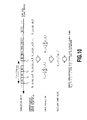
Fig. 10 shows the case where the vector averaging
process as the equalizing process in the second embodiment
of the synchronization detection method. In the vector
averaging process, the received signal vector of each
synchronization timing candidate is averaged respectively
on I side and Q side (N in number). Subsequently, the
received signal power is calculated from the values of I
and Q after averaging, the synchronization chip of the
channel to be measures is determined. Since the vector
averaging process is premised in that the phase rotation
of the desired signal vector due to fading in the averaging
period can be ignored, in the example shown in Fig. 10,
a sampling interval per one synchronization timing
candidate is set at 1/15 msec.
In the foregoing vector averaging process, by
increasing number of samples to be averaged, the average
value of the power of the received signal other than the
true synchronization chip timing becomes small (standard
deviation is unchanged).
Fig. 11 shows a received signal power distribution
after performing vector averaging process as the
equalizing process. After detection of partial
correlation for a certain scrambling code at 256 chip
length and averaging power in sample number 5, 10 and 15,
Fig. 11 shows a distribution of the power value of the
received signal at a timing other than true
synchronization chip timing. However, fading is not added.
As can be appreciated from Fig. 11, when the sample number
N is increased, the average value of the power of the
received signal in the true synchronization chip timing
becomes smaller. As a result, probability of success of
detection of synchronization becomes high.
Fig. 12 shows a synchronization chip timing
detection procedure in the vector averaging process. At
step S21, synchronization detection is initiated. At step
S22, synchronization timing candidate is set (i = 0). At
step S23, partial correlation calculation is performed.
At step S24, check is performed whether k < N is satisfied
or not. At step S25, k is incremented. At step S6, vector
average is derived for all chip timing of synchronization
timing candidate #i. At step S27, the power values are
calculated for all chip timing of the synchronization
timing candidate #i. At step S28, check is performed
whether i < max i is satisfied or not. At step S29, i is
incremented. At step S30, retrieval of the maximum power
of the received signal is performed for all
synchronization timing candidate or all chip timing. At
step S31, the synchronization chip timing is determined.
At step S32, synchronization detection is terminated.
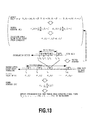
Fig. 13 shows a principle of operation of the third
embodiment of the synchronization detection method
according to the present invention. The third embodiment
of the synchronization detection method is further
improvement of the second embodiment set forth above.
Namely, process of equalizing process can be set for a
plurality of times. Even in each process, using the
average value obtained by averaging for a plurality of
times by the same or different averaging method, the
synchronization chip timing of the channel to be measures
is determined.
In the third embodiment, averaging operation is
repeated twice. At the first stage of averaging, N1 in
number of vector averaging process is performed per
synchronization timing candidate. Subsequently, the
power value is derived from the received signal vector
after vector averaging for deriving N2 in number of
averaged values. At the second stage, the chip timing
where the received signal power after averaging becomes
maximum, is detected to the synchronization chip timing
of the channel to be measured.
In the third embodiment, at first, in the first stage
averaging, the average value of the received signal power
in the synchronization chip timing other than the true
synchronization chip timing becomes small for N1 in number
of samples. Subsequently, by averaging in the second
stage, the standard deviation becomes smaller than N2 in
number of samples. As a result, probability of success
in detection of synchronization becomes further higher in
comparison with the case of one time of averaging operation.
In the third embodiment, a period required for
synchronization detection is (N1 x N2 x 10) msec.
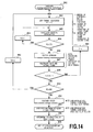
Fig. 14 shows a synchronization chip timing
detection procedure in the third embodiment of
synchronization detection method. At step S41,
synchronization detection is initiated. At step S42,
synchronization timing candidate is set (i = 0). At step
S43, partial correlation calculation is performed. At
step S44, check is performed whether k1 < N1 is satisfied
or not. At step S45, k1 is incremented. At step S46,
vector average is derived for all chip timing of
synchronization timing candidate #i. At step S47, the
power values are calculated for all chip timing of the
synchronization timing candidate #i. At step S48, check
is performed whether i < max i is satisfied or not. At
step S49, i is incremented. At step S50, check is
performed whether k2 < N2 is satisfied or not. At step
S51, k2 is incremented. At step S52, power averaging is
performed at all synchronization timing candidate or all
chip timing. At step S53, retrieval of the maximum power
of the received signal is performed for all
synchronization timing candidate or all chip timing. At
step S54, the synchronization chip timing is determined.
At step S55, synchronization detection is terminated.
Furthermore, the fourth embodiment of the
synchronization detection method will be explained. The
fourth embodiment determines the synchronization chip
timing of the channel to be measured by performing
synchronization chip timing detection process in the
foregoing first to third embodiments for a plurality of
times and using the averaged value of a plurality of
synchronization chip timing values and the standard
deviation value. Therefore, in the fourth embodiment,
check is performed whether the detected synchronization
chip timing is reasonable or not.
Fig. 15 shows a principle of operation of the fourth
embodiment of the synchronization detection method
according to the present invention. M in number of
synchronization chip timings detected after averaging are
prepared. Then, the synchronization chip timing as object
for measurement is checked. It should be noted that, in
the fourth embodiment, complete synchronization detection
is not required and it is only required to have a value
falling within certain range (measurement window).
The fourth embodiment is premised in that
measurement of all chip timing in measurement window is
performed after synchronization detection. At first, an
averaged value of M in number of detected synchronization
chip timings. Subsequently, using the average value thus
derived, the standard deviation is derived. As an
averaged value derived centered at the measurement window,
the value of the derived standard deviation falls within
the measurement window width, measurement becomes
possible to take the detection successful. On the other
hand, when the derived standard deviation does not fall
within the measurement window, judgment is made that
probability of failure of detection is high to again
initiate synchronization detection.
Next, explanation will be given for the
synchronization detection method in the case where
transmit diversity is applied in CPICH.
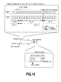
Fig. 16 shows the frame structure of CPICH and the
received signal in the case where the transmit diversity
is applied. α1 is a vector variation amount depending
upon propagation path from the transmission antenna #1 of
the base station to the mobile station, α2 is a vector
variation amount depending upon propagation path from the
transmission antenna #2 of the base station to the mobile
station. These are varied from time to time according to
movement of place of the mobile station. On the other hand,
the signal transmitted from each antenna of the base
station is provided modulation of A or -A per symbol. This
pattern is determined uniquely. It should be noted that
symbol modulation pattern when the transmit diversity is
not applied, is the same as that of the antenna #1.
CPICH transmitted from the antenna #1 and the antenna
#2 are influenced by each propagation path. In the mobile
station, the signals in combined form are received.
Accordingly, the signal of symbol #0 transmitted from the
base station is received in the mobile receiving station
as expressed by the following equation:
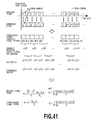
R(0) = P t1 α1(0)·A + P t2 α2(0)·A + N(0)
wherein R(0) is the received signal vector after
correlation detection, Pt1 and Pt2 are transmitting power
of CPICH in respective transmission antennas, N(0) is
interference signal vector.
The synchronization detection is detection of the
position of symbol #0 in the mobile receiving station. It
should be noted that communication quality measurement
upon use of transmit diversity which will be discussed
later, is derivation of the desired signal power as
expressed by:
〈Pt1 |α1|2 + Pt2 |α2|2〉
and the interference power as expressed by:
〈|N|2〉
wherein 〈 〉 expresses an average.
Next, the received signal vector combined as
expressed by the foregoing expression (1) will be
separated into the received signal vector from each
transmission antenna. For separation, two continuous
symbols are used. Assuming (i)th symbol (wherein i is even
number) as a symbol to be a reference, the received signal
vector r
1 and r
2 from each antenna is expressed by:
The foregoing equation (4) use approximations of α
1(i +
1) ≒ α
1(i) and α
2(i + 1) ≒ α
2(i).
Fig. 17 shows a principle of operation of the fourth
embodiment of the synchronization detection method
according to the present invention. The synchronization
detection detects leading position (synchronization chip
timing) of CPICH from the received signal. #0 to #149 in
Fig. 17 are synchronization timing candidates generated
by the synchronization timing candidate generating
portion 2210 shown in Fig. 2. It should be noted that unit
for blocking is one symbol. Calculation of correlation
with the received signal is performed by sequentially
extracting objective symbol number among the
synchronization timing candidates #0 to #149 and using
spreading code (256 chip length) corresponding to the
symbol number.
For example, assuming an average number of vector
is N1, from the synchronization timing candidate #i, 2N1
+ 1 in number of symbols in series from 2(N1 + 1)i is selected
for correlation calculation. When matched filter is used
in correlation calculation, a timing to finish correlation
calculation for all of the synchronization timing
candidates is T1 = 10 x (2N1 + 1) [ms].
Next, from the obtained received signal vector R(i)
and R(i + 1), the received signal vector from each
transmission antenna is separated using the foregoing
equation (4). Here, number of received signal vectors
after separation belonging in the same synchronization
timing candidates is N1 in number per one transmission
antenna. These N1 in number of received signal vectors
averaged per transmission antenna, and finally, obtained
two average vectors are summed in power. Fig. 17 shows
the case where the number of vector average N1 is 2. In
practice, the foregoing calculation is performed for all
of 256 chips. On the other hand, the foregoing calculation
is executed with over-sampling of X times of one symbol,
calculation is performed for number of samples of 256 x
X. The synchronization chip timing is determined by
synchronization timing candidate having the maximum power
value and the chip number in the symbol.
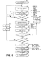
Fig. 18 shows the synchronization chip timing
detection procedure in the sixth embodiment of the
synchronization detection method. In the shown
embodiment, except for the period required for calculation,
a period from initiation of synchronization detection to
finishing thereof is T1 = 10 x (2N1 + 1) x N2 [ms].
At step S61, synchronization detection is
initiated. At step S62, synchronization timing candidate
is set (i = 0). At step S63, partial correlation
calculation is performed. At step S64, check is performed
whether k1 < 2N1 + 1 is satisfied or not. At step S65,
k1 is incremented. At step S66, received signal vector
is separated per antenna with respect to all chip timings
of the synchronization timing candidates. At step S67,
vector averages of the received signal vectors are derived.
At step S68, the averaged received signal vector is
converted into the power value per antenna and then the
power values of respective antennas are summed.
At step S69, check is performed whether i < max i
is satisfied or not. At step S70, i is incremented. At
step S71, k1 is reset to 0. At step S72, check is performed
whether k2 < N2 is satisfied or not. At step S73, k2 is
incremented. At step S74, k1 is reset to 0. At step S75,
power averaging is performed at all synchronization timing
candidates or all chip timing. At step S76, retrieval of
the maximum power of the received signal is performed for
all synchronization timing candidates or all chip timing.
At step S77, the synchronization chip timing is determined.
At step S78, synchronization detection is terminated.
(2) Communication Quality Measuring Method
Next, the measurement method of communication
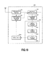
quality will be explained. Fig. 19 shows overall
construction of the mobile station, to which the present
invention is applied. The mobile station 202 has the same
construction as that of Fig. 2. The communication quality
calculating portion 224 includes matrix calculation means
2301 for deriving covariant matrix from two time series
data in the received signal vector generated in the time
series generating portion 223 and performing calculation
of eigenvalues, power calculating means 2302 for
calculating the desired signal power and the interference
signal value using the eigenvalues, and SIR calculating
means for deriving SIR.
On the other hand, using a control portion 2304 as
component of the mobile communication system, a path
between transmitter and receiver effective for
communication is derived using the SIR value derived in
the SIR calculation means to control the synchronization
chip timing information portion 225 for achieving
measurement of more precise value.
In the shown embodiment, with reference to the
synchronization chip timing obtained in the
synchronization detecting portion, all chip timings in a
certain range are taken as object for measurement. Namely,
communication quality measurement using the measurement
window is performed.
Fig. 20 shows a principle of operation of the first
embodiment of the communication quality measuring method
according to the present invention, a chip length to
perform correlation detection and the measurement window
width is taken as one symbol. Here, consideration is given
for chip timing k presenting in the measurement window.
In order to derive the desired signal power and the
interference signal power in the chip timing k, a series
1 is established by arranging the received signal vector
of the chip timing 1 in a certain given period (averaged
period, and a series 2 is established by a time series data
of the received signal vector distanced from the series
2 for several symbols.
Next, covariant matrix of the series 1 and the series
2 is derived to calculate eigenvalues thereof. By
performing operation shown in Fig. 20 using the
eigenvalues thus derived, the desired signal power and the
interference signal power at the chip timing k can be
derived as averaged values within the averaging period.
It should be noted that the operation for deriving the
powers from the eigenvalues shown in Fig. 20 is effective
only when correlation between two series is relatively
high. In other words, the foregoing operation is only
effective when the time difference between two series is
sufficiently small relative to a variation of the desired
signal vector due to multi-path fading. In the shown
embodiment, there is no limitation in sampling interval
(data interval in one series) and number of samples (number
of data in one series).
It should be noted that greater number of samples
within the averaging period results is closer value to the
true value. On the other hand, SIR in the chip timing k
can be derived from a ratio of the obtained desired signal
power and the interference signal power. On the other hand,
in case of communication quality measurement not using the
measurement window, the synchronization chip timing
obtained by the synchronization detecting portion may be
measured as the chip timing k.
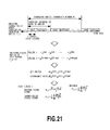
Fig. 21 shows a principle of operation of the second
embodiment of the communication quality measurement
method according to the present invention. When
correlation between two series, namely when the
correlation value is greater than or equal to 0.85, the
desired signal power and the interference signal power can
be derived from an add vector and difference vector
relative to the received signal vectors having reception
timing close to each other between time series. More
preferably, at the correlation value greater than or equal
to 0.9, the desired signal power and the interference
signal value are derived at comparable precision as the
first embodiment of Fig. 20. Further preferably, at the
correlation value greater than or equal to 0.95, the
desired signal power and the interference signal value are
derived at comparable precision as the first embodiment
of Fig. 20 and with more simple calculation method.
In the shown embodiment, a time difference between
time series (delay time difference) as one symbol, the add
vector and difference vector are derived from the received
signal vector between adjacent symbols. At first, using
N in number of difference vector within the averaging
period, the interference signal power is derived by
operation shown in Fig. 21. Next, the desired signal power
is derived using N in number of add vectors within the
averaging period and already derived interference signal
power. From a ratio of the derived desired signal power
and the interference signal power, SIR in the averaging
period can be derived. Even in the shown embodiment,
similarly to the first embodiment shown in Fig. 20, there
is basically no limitation for the sampling interval and
the sampling number.
In the shown embodiment, in the time series
generating portion 223 shown in Fig. 19, in addition to
generation of two time series data of the received signal
vector, generation of time series data of the add vector
and difference vector is also performed. It should be
noted that, in the shown embodiment, since the eigenvalues
are not required, matrix operation shown in Fig. 19 becomes
unnecessary.
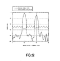
Fig. 22 shows a result of simulation in the second
embodiment of the communication quality measuring method.
Namely, Fig. 22 shows examples of the result of output of
the desired signal power and the interference signal
within the measurement window derived by simulation. In
the simulation, it is assumed that two signals, in which
a certain code is spread, arrive with 5 chip delay. Namely,
the position of the first path is tenth chip and the
position of the second path is fifteenth chip. The signal
arriving at the second path acts as interference signal
in the first path and the signal arriving at the first path
acts as interference signal in the second path. The
averaging period is 1500 symbols and the sampling interval
is 1 symbol. It should be noted that the power of the
signal arriving at the second path is set to be 5 dB lower
than the power of the signal arriving at the first path.
The correlation detection is perform with four times
over-sampling of 256 chip length.
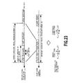
Fig. 23 shows a principle of operation of the third
embodiment of the communication quality measuring method
according to the present invention. In the shown
embodiment, by averaging the desired signal power and the
interference signal power derived in the foregoing first
and second embodiments, more stable value (average value)
can be obtained. In the shown embodiment, at first, an
average values of the desired signal power and the
interference signal power are derived per N1 in number of
chips in the average period using the methods in the first
and second embodiments (primary averaging). Then, as
secondary averaging, N2 in number of desired signal powers
and the interference signal powers obtained by the primary
averaging are averaged in power. It should be noted that
SIR in the averaging period is derived from a ratio of the
derived desired signal power and the interference signal
power.
Fig. 24 shows a result of simulation by the third
embodiment of the communication quality measuring method.
Condition of simulation is the same as those of Fig. 22
except for averaging method. Averaging sample number is
5 in the primary averaging and 300 in the second averaging.
The averaging period in total is 1500 symbols. Comparing
with the results shown in Fig. 22, it should be appreciated
that more stable values can be obtained.
Fig. 25 shows a principle of operation of the fourth
embodiment of the communication quality measuring method
according to the present invention. In the shown
embodiment, number of channels to be measured is assumed
to be M. The reason why the same channels are continuous
for two symbols, is that two series data are required by
the averaging methods in the first and second embodiments.
As shown in Fig. 25, with taking two symbols as set,
measurement of other channel within the sampling period
becomes possible. In a certain given period, measurement
data of a plurality of channels can be obtained at
substantially the same. In the prior art using the vector
averaging, since there is a limitation that "phase
variation of the desired signal vector due to multi-path
fading in the averaging period, should be ignorable."
Therefore, when number of channels to be measured is large
number and the averaging period is relatively long, time
multiplexing of other channel within the sample period is
difficult.
Fig. 26 shows a principle of operation of the fifth
embodiment of the communication quality measuring method
according to the present invention. In the shown
embodiment, primary average is derived by time
multiplexing of other channels within sampling period of
one channel. Then, secondary averaging (averaging in
power) is performed from the result obtained by the primary
averaging.
Fig. 27 shows a principle of operation of the sixth
embodiment of the communication quality measuring method
according to the present invention. In the shown
embodiment, at first, primary averaging is performed per
one channel, and other channels are multiplexed in the
secondary averaging period to obtain the values after
secondary averaging of respective channels.
Figs. 28A and 28B show the results of simulation in
the fifth embodiment of the communication quality
measuring method. Fig. 28A is a profile of obtained
received signal power performing simulation in the same
condition as Figs. 22 and 24. The averaging method
performs only averaging in power per chip. Fig. 28B is
a profile of SIR per each chip derived using the desired
signal power and the interference signal power obtained
from Fig. 22. Conventionally, the position of the path
to be effective in communication is detected as the
synchronization chip timing from the peak where the power
becomes maximum by deriving the received signal power per
chip in the synchronization detecting portion 221 shown
in Fig. 19, as shown in Fig. 28A.
In Fig. 28A, since the desired signal power is set
relatively higher than the interference signal power, the
path position can be easily detected from the peak value
thereof. However, according to increase of the
interference signal power, judgment whether the peak value
is the actual path position or not, is difficult. On the
other hand, it is not possible to distinguish whether the
peak is results in presence of the path or the peak is
results in fluctuation of noise only by the peak value of
the power. When error is present in the synchronization
chip timing in the synchronization detecting portion 221,
precision in measurement is degraded since the measurement
is performed at a chip timing different from the path
position effective for communication, in the
communication quality measuring portion 224.
On the other hand, in the shown embodiment, the
synchronization chip timing obtained in the
synchronization detecting portion 221 is taken as the
reception chip timing to measure SIR by the first and second
embodiments. In the control portion 2304 shown in Fig.
19, judgment is made whether the reception chip timing is
offset from the path position effective for communication
from the measured SIR value or not. If judgment is made
that the reception chip timing is offset from the path
position, the synchronization chip timing information
portion 225 shown in Fig. 19 is controlled to modify the
synchronization chip timing.
On the other hand, in case of the communication
quality measurement premised by the measurement window,
for all chip timing in the measurement window, the desired
signal power, the interference signal power and SIR are
measured. Therefore, SIR profile shown in Fig. 28B is
obtained. In Fig. 28B, SIR < 0 is certainly established
at positions where the path is not present, and SIR > 0
is established at positions where the path is present. In
the control portion 2304 shown in Fig. 19, the peak value
where SIR > 0 is established is detected to detect the path
position effective for communication.
When judgment is made that the position of the
measuring window and the window width are not appropriate,
modification of the position of the measuring window and
the window width is performed by controlling the
synchronization chip timing information portion 225 of Fig.
19. By such control, even when the path position between
transmitter and receiver is moved by movement of the mobile
station, the position of the window is modified following
movement of the path. As a result, moving measurement of
the communication quality can be realized without causing
degradation of precision.
(3) Communication Quality Measuring Method Upon Use of
Transmit Diversity
Fig. 29 shows overall construction of the mobile
communication system applying transmit diversity. The
mobile station 202 has the same construction as that shown
in Fig. 2. The time series generating portion 223 is
constructed with a delay circuit 3301 delaying the
received signal vector after correlation detection for a
predetermined delay symbol number, a vector calculation
portion 3302 deriving a difference vector and add vector
from difference and sum of the received signal vector, and
a vector selecting portion 3303 selecting vector for
performing calculation by the communication quality
calculating portion 224.
When communication is performed applying transmit
diversity as the channel to be measured, the channel
repeatedly transmitted a known symbol series of
respectively different patterns using common spreading
code is assumed from two different antennas of the radio
base station. When the communication applying transmit
diversity is not performed, the channel repeatedly
transmitted a known transmission symbol series is assumed.
While two antennas of the radio base stations are located
close to each other, the distance of the antennas is set
to make the spatial correlation small. At receiving point
in the service area, the signal reaches as a signal
influenced by independent propagation path. The signals
transmitted from two antennas are received by the antenna
at the reception point as combined in vector in space.
Fig. 30 is an illustration for explaining process
for explaining correlation detection process in one
embodiment of the present invention. In general, a
transmission series s1(t) from the antenna #1 and a
transmission series s2(t) from the antenna #2 are subject
to respectively independent fading c1(t) and c2(t). These
two series are received after combination in the space.
Accordingly, ignoring transmission delay, a received
series becomes r(t) = c1(t) * s1(t) + c2(t) * s2(t). Here,
considering a time range where influences of the
propagation paths are regarded as the same, fading can be
regarded as constant, c1(t) = c1 and c2(t) = c2. Therefore,
the received series becomes a given value per combination
of the transmission series s1(t) and s2(t).
For example, when the symbol of the transmission
series of the antenna #1 at a certain timing is assumed
as A and the symbol of the transmission series of the
antenna #2 at the certain timing is assumed as A, the
received series becomes X. When the symbol of the
transmission series of the antenna #1 at a certain timing
is assumed as A and the symbol of the transmission series
of the antenna #2 at the certain timing is assumed as B,
the received series becomes Y. As set forth above, in a
time range where the influence of the propagation path is
regarded as constant, the received series is determined
only depending upon the transmission series.
In this circumstance, in the transmission series,
if the regular pattern is periodically and repeatedly
transmitted, certain series pattern is repeated in the
same period in the received series. At this time, when
a correlation value between the received series and the
delayed received series delayed for a period of the regular
series pattern is derived, the derived value becomes 1.
Namely, the delayed received series delayed for the period
of the transmitted series pattern and the received series
are completely matched and the mutual correlation between
the series becomes 1. Here, on transmission side, a unit
where the known series pattern is repeated for a plurality
of times is defined as frame.
Fig. 31 shows a process of correlation detection in
one embodiment of the present invention. A symbol as
correlation unit taking tj+1 + iΔ τ as leading end of the
received series r'(t), is assumed as r'(tj+1 + iΔ τ), and
correlation detection process is performed by the
correlation detector, such as matched filter set the code
m(tj+1 + iΔ τ) spreading respective of corresponding symbol,
the received signal vector series r(tj+1 + iΔ τ) after
correlation can be obtained. Thus, the received signal
vector is assumed as rk(tj+1 + iΔ τ). It should be noted
that Δ τ is a period of one symbol length, j is a repetition
number of the series pattern in one frame, i is symbol
number in the pattern, k is a reception chip timing in the
symbol. On the other hand, it is assumed that information
of the leading end position, the symbol position and so
on of the channel frame to be measured are already known.
Fig. 32 shows a delay process in one embodiment of
the present invention. With a preliminarily set delay
symbol number I, by delaying the received signal vector
series after correlation detection for delay symbol number
I, the delayed received signal vector series is generated.
The delay symbol number I us set at integer multiple of
the repetition period of the transmission series pattern.
Fig. 33 shows vector calculation process in one
embodiment of the present invention. In two time series
data of the received signal vector series r(t) after
correlation and the delayed received signal vector series
r(t - IΔ τ) delayed for delay symbol number I, the received
signal vector rk(tj+1 + iΔ τ) in the reception chip timing
k in the symbol and from difference and sum of the received
signal vector series rk(tj+1 + iΔ τ - IΔτ), namely rk(tj
+ iΔ τ ) at the same reception chip timing, at which the
series is delayed for delay symbol I, difference vector
and add vector are derived. The add vector becomes αi_k(tj)
= rk(tj+1 + iΔ τ) + rk(tj + iΔ τ) and the difference vector
becomes βi_k(tj) = rk(tj+1 + iΔτ) - rk(tj+ iΔτ).
Fig. 34 shows a process of vector selection and a
process of communication quality calculation in one
embodiment of the present invention. The vector selection
selects output of the vector calculation process to be
input to the communication quality calculation process by
a preliminarily set vector selection information seli_k(tj),
namely the difference vector and the add vector. The
vector selection information is information ON = 1 and OFF
= 0 per symbol.
The communication quality calculation uses input add
vector α'i_k(tj) and the difference vector β 'i_k(tj). From
an average of the difference vector, the interference
signal power is derived, and from an average of the add
vector and the average of the difference vector, the
desired signal power is derived. SIR is derived from a
ratio of the desired signal power and the interference
signal power.
Fig. 35 shows CPICH upon use of the transmit diversity
in the mobile communication system using W-CDMA cellular
system. CPICH is consisted of 150 symbols per one frame,
a symbol series consisted of four symbols (A, A, A, A) is
transmitted from the antenna #1 and a symbol series
consisted of four symbols (A, B, B, A) is transmitted from
the antenna #2. Since the transmission symbol series is
once reset per one frame, regularity of the four symbol
period is not continued at the boundary of the frame.
Therefore, in order to obtain a series where the
correlation of the transmission symbol series becomes 1,
the delay period has to be set at one frame. However, in
case of the series provided such long delay should go beyond
the range where the influence of the propagation path is
constant to make it difficult to derive correct add vector
and difference vector.
In order to avoid this, there are a method for
selecting only correct add vector and the difference
vector by setting the delay period to four symbols to avoid
frame boundary, the delay period symbol is taken as one
symbol, and a method for selecting only correct add vector
and the difference vector appearing every other symbol
with taking one symbol as the delay period symbol.
Fig. 36 shows a principle of operation of the first
embodiment of the communication quality measuring method
upon use of the transmit diversity according to the present
invention. The synchronization detection is calculated
with taking four symbols as the delay period. Among 150
symbols in one frame, 146 symbols matches symbol of the
series 2, 4 symbols from the frame boundary do not match
with the symbols in series 2. Therefore, the correlation
value of the series 1 and the series 2 can not be 1. Since
this make is difficult to derive correct add vector and
difference vector, by setting the vector information of
part of unmatched symbol in the frame boundary in the vector
selection process, result of correct calculation can be
obtained in the communication quality calculating
process.
Fig. 37 shows a principle of operation of the second
embodiment of the communication quality measuring method
upon use of the transmit diversity according to the present
invention. Communication quality is calculated with
tasking one symbol as delay period. In the series 1,
excluding first symbol from the leading end of the frame,
odd number order symbol match with the symbols in the series
2, but even number order symbols from the leading end of
the frame do not match. Therefore, the correlation value
of the series 1 and series 2 does not become 1. With
leaving this, correct add vector and the difference vector
can be calculated. Therefore, by setting vector
information to off = 0 for the first and even number order
symbols from the leading end of the frame, correct result
of calculation can be obtained in the communication
quality calculation process.
Fig. 38 shows CPICH when transmit diversity is not
applied in the mobile communication system used in W-CDMA
cellular system. The pilot channel is consisted of 150
symbols for one frame. A symbol series consisted of four
symbols (A, A, A, A) is repeatedly transmitted only from
the antenna #1 with taking four symbol as a period. While
the transmission symbol series is reset per one frame,
since symbol is constant, non-continuous at the frame
boundary is not generated. Therefore, by applying any
delay period, correlation of the transmission symbol
series becomes 1. Accordingly, at arbitrary delay period
where time correlation of the propagation path becomes
small, correct add vector and difference vector can be
derived.
This demonstrates capability of correct measurement
of the desired signal power and the interference signal
power when the transmit diversity is not applied using
either the method of calculating the communication quality
with taking four symbols as delay period as shown in Fig.
36 or the method of calculating the communication quality
with taking one symbol as delay period as shown in Fig.
37. Accordingly, even when the base stations applying the
transmit diversity and the base stations not applying the
transmit diversity are present, it becomes unnecessary to
change calculation method and the calculation method is
used commonly.
Fig. 39 shows a principle of operation of the third
embodiment of the communication quality measuring method
upon use of the transmit diversity according to the present
invention. With taking CPICH as channel to be measured
upon use of the transmit diversity, the communication
quality measuring method which does not require the vector
selecting portion 223 shown in Fig. 29, is illustrated.
The synchronization chip timing detected by the
synchronization detecting portion 221 and accumulated in
the synchronization chip timing information portion 225
is taken as reception chip timing. Then, detection of
correlation is performed with modifying the spreading code
of a reference signal adapting to the symbol number of the
received signals. The received signal vector for each
transmission antenna is calculated from the foregoing
equation (4) using the received signal vector obtained by
correlation detection.
Next, the add vector and the difference vector are
generated per each transmission antenna. The desired
signal power and the interference signal power upon use
of transmit diversity are derived from the add vector and
the difference vector for each antenna. In Fig. 39, N upon
deriving the desired signal power and the interference
signal power is number of samples of the add vector or the
difference vector per one transmission antenna. For
example, when the averaging period is 150 symbols (number
of symbols in one frame), for example, N becomes 74. On
the other hand, in Fig. 39, correlation detection is
performed from the leading end of the frame for
simplification, correlation detection is not necessarily
performed from the leading end.
Fig. 40 shows the result of simulation in the third
embodiment of the communication quality measuring method
upon use of transmit diversity. Under the premise of
synchronization quality measurement using the measuring
window, 4 times of over-sampling points is performed for
the chip timing. Simulation is performed to set the
received power of the desired signal at 0 dBm (-3 dBm for
each antenna), the received power of the interference
signal at -100 dBm, and the path position between
transmitter and receiver at tenth chip in the measurement
window. From Fig. 40, at set path position between
transmitter and receiver, the desired signal power and the
interference signal power can be calculated with high
precision.
Fig. 41 shows a principle of operation of the fourth
embodiment of the communication quality measuring method
upon use of the transmit diversity according to the present
invention. With taking CPICH as the channel to be measured
upon applied of transmit diversity, the communication
quality measuring method not requiring the vector
selecting process 223 of Fig. 29 will be explained. In
the shown embodiment, from the received signal vector
obtained from correlation detection, only received signal
vector for one transmission antenna is derived from the
foregoing equation (4). Here, the transmission antenna
to be selected is either antenna #1 or antenna #2.
Calculation is simple as the antenna #1 is selected. In
Fig. 41, the antenna #1 is selected as the selected
transmission antenna.
Next, for the obtained received signal vector in one
transmission antenna, the add vector and the difference
vector are generated. The desired signal power and the
interference signal power upon use of transmit diversity
are calculated from the add vector and the difference
vector. In Fig. 41, N upon deriving the desired signal
power and the interference signal power is number of
samples of the add vector or the difference vector per one
transmission antenna. For example, when the averaging
period is 150 symbols (number of symbols in one frame),
for example, N becomes 74. On the other hand, upon
derivation of the desired signal power and the
interference signal power, (Pt1 + Pt2)/Pt1 is a correlation
value which is a known value. Here, Pt1 and Pt2 are
transmitting power of CPICH in each transmission antenna.
It should be noted that, in Fig. 41, correlation detection
is performed from the leading end of the frame for
simplification. However, correlation detection can be
not necessarily performed from the leading end.
Fig. 42 shows a result of simulation in the fourth
embodiment of the communication quality measuring method
upon use of transmit diversity. Condition of simulation
is the same as Fig. 40. Fig. 42 shows the value before
correction by the transmitting power. At the path
position between the transmitter and receiver, it can be
appreciated that the desired signal power and the
interference signal power are calculated at -3 dB lower
than the set values. On the other hand, the correction
value is (Pt1 + Pt2)/Pt1 = 2 (3 dB). Accordingly, by adding
the correction value of 3 dB, the desired signal power and
the interference signal power can be correctly measured.