EP1143467A2 - Microelectromechanical actuators including driven arched beams for mechanical advantage - Google Patents
Microelectromechanical actuators including driven arched beams for mechanical advantage Download PDFInfo
- Publication number
- EP1143467A2 EP1143467A2 EP01302514A EP01302514A EP1143467A2 EP 1143467 A2 EP1143467 A2 EP 1143467A2 EP 01302514 A EP01302514 A EP 01302514A EP 01302514 A EP01302514 A EP 01302514A EP 1143467 A2 EP1143467 A2 EP 1143467A2
- Authority
- EP
- European Patent Office
- Prior art keywords
- driven
- substrate
- arched
- beams
- arched beams
- Prior art date
- Legal status (The legal status is an assumption and is not a legal conclusion. Google has not performed a legal analysis and makes no representation as to the accuracy of the status listed.)
- Granted
Links
Images





Classifications
-
- B—PERFORMING OPERATIONS; TRANSPORTING
- B81—MICROSTRUCTURAL TECHNOLOGY
- B81B—MICROSTRUCTURAL DEVICES OR SYSTEMS, e.g. MICROMECHANICAL DEVICES
- B81B7/00—Microstructural systems ; Auxiliary parts of microstructural devices or systems
- B81B7/02—Microstructural systems ; Auxiliary parts of microstructural devices or systems containing distinct electrical or optical devices of particular relevance for their function, e.g. microelectro-mechanical systems [MEMS]
-
- H—ELECTRICITY
- H01—ELECTRIC ELEMENTS
- H01H—ELECTRIC SWITCHES; RELAYS; SELECTORS; EMERGENCY PROTECTIVE DEVICES
- H01H1/00—Contacts
- H01H1/0036—Switches making use of microelectromechanical systems [MEMS]
-
- H—ELECTRICITY
- H01—ELECTRIC ELEMENTS
- H01H—ELECTRIC SWITCHES; RELAYS; SELECTORS; EMERGENCY PROTECTIVE DEVICES
- H01H61/00—Electrothermal relays
- H01H2061/006—Micromechanical thermal relay
-
- H—ELECTRICITY
- H01—ELECTRIC ELEMENTS
- H01H—ELECTRIC SWITCHES; RELAYS; SELECTORS; EMERGENCY PROTECTIVE DEVICES
- H01H61/00—Electrothermal relays
- H01H61/02—Electrothermal relays wherein the thermally-sensitive member is heated indirectly, e.g. resistively, inductively
Definitions
- This invention relates to microelectromechanical systems (MEMS), and more specifically to MEMS actuators.
- MEMS Microelectromechanical systems
- electromechanical devices such as relays, actuators, valves and sensors.
- MEMS devices are potentially low-cost devices, due to the use of microelectronic fabrication techniques.
- New functionality also may be provided, because MEMS devices can be much smaller than conventional electromechanical devices.
- MEMS actuators may use one or more beams that are fixed at one or both ends. These actuators may be actuated electrostatically, magnetically, thermally and/or using other forms of energy.
- a coupler can be used to mechanically couple multiple arched beams.
- At least one compensating arched beam also can be included which is arched in a second direction opposite to the multiple arched beams and also is mechanically coupled to the coupler.
- the compensating arched beams can compensate for ambient temperature or other effects to allow for self-compensating actuators and sensors.
- Thermal arched beams can be used to provide actuators, relays, sensors, microvalves and other MEMS devices. Thermal arched beam microelectromechanical devices and associated fabrication methods also are described in U.S. Patent 5,955,817 to Dhuler et al.
- MEMS actuators continue to proliferate and to be used in more applications and environments, it would be desirable to allow the displacement and/or force of MEMS actuators to be controlled over wider ranges.
- Microelectromechanical actuators include a substrate, spaced apart supports on the substrate and a thermal arched beam that extends between the spaced apart supports and that further arches upon heating thereof, for movement along the substrate.
- a plurality of driven arched beams are coupled to the thermal arched beam. The end portions of the respective driven arched beams move relative to one another to change the arching of the respective driven arched beams in response to the further arching of the thermal arched beam, for movement of the driven arched beams.
- a respective driven arched beam also includes a respective actuated element at an intermediate portion thereof between the end portions, wherein a respective actuated element is mechanically coupled to the associated driven arched beam for movement therewith, and is mechanically decoupled from the remaining driven arched beams for movement independent thereof.
- the plurality of driven arched beams comprise first and second driven arched beams that extend parallel to one another, such that the actuated elements that are mechanically coupled to the first and second driven arched beams move in a same direction by the further arching of the thermal arched beam.
- the first and second arched beams arch away from each other, such that the actuated elements that are coupled to the first and second driven arched beams move in opposite directions by the further arching of the thermal arched beam.
- the first and second driven arched beams arch toward one another, such that the actuated elements that are mechanically coupled to the first and second driven arched beams move in opposite directions by the further arching of the thermal arched beam.
- the respective end portions are squeezed together by the further arching of the thermal arched beam, to thereby increase arching of the driven arched beam.
- the end portions are pulled apart by the further arching of the thermal arched beam, to thereby decrease arching of the driven arched beams.
- the thermal arched beam includes an intermediate portion between the end portions, and the driven arched beams include intermediate portions between the respective end portions thereof.
- the intermediate portions of the thermal arched beams are coupled to one of the end portions of the driven arched beams.
- the intermediate portion of a second thermal arched beam is coupled to the other of the end portions of the driven arched beams.
- An H-shaped microelectromechanical actuator thereby is formed, wherein each leg of the H comprises a thermally activated arched beam, and the cross-members of the H comprises mechanically activated driven arched beams.
- an anchor is provided that anchors the other end portions of the driven arched beams to the substrate.
- thermo arched beam actuator only one end of the driven arched beams is driven by a thermal arched beam actuator.
- These embodiments thereby form microelectromechanical actuators having a T-shape, wherein the cross-member of the T comprises a thermally activated arched beam and wherein the leg of the T comprises mechanically activated arched beams.
- the thermal arched beam extends between the spaced apart supports along a first direction on the substrate, and further arches upon heating thereof, for movement along the substrate in a second direction that is orthogonal to the first direction.
- the driven arched beams extend along the substrate in the second direction and the arching of the driven arched beams is changed in the first direction by the further arching of the thermal arched beam for movement along a substrate in the first direction.
- second spaced apart supports are provided on the substrate, and a second thermal arched beam is provided that extends between the second spaced apart supports and that further arches upon heating thereof for movement along the substrate.
- the driven arched beams are coupled to the first and second thermal arched beams, such that the arching of the driven arched beams is changed by the further arching of the first and second thermal arched beams. More preferably, the intermediate portion of the first thermal arched beam is coupled to one end portion of the respective driven arched beams, and the intermediate portion of the second thermal arched beam is coupled to the other end portion of the respective driven arched beams.
- the first and second thermal arched beams extend between the respective first and second spaced apart supports along a first direction on the substrate, and further arch upon application of heat thereto, for movement along the substrate in a second direction that is orthogonal to the first direction.
- the driven arched beams extend along the substrate in the second direction, and the arching of the driven arched beams are changed in the first direction by the further arching of at least one of the thermal arched beams for movement along a substrate in the first direction.
- the first and second thermal arched beams extend between the respective first and second spaced apart supports along a first direction on the substrate, and further arch upon application of heat thereto, for movement along the substrate in respective opposite directions that are orthogonal to the first direction.
- the driven arched beams extend along the substrate along the second opposite directions, and the arching of the driven arched beams are changed in the first direction by the further arching of the thermal arched beams, for movement along the substrate in the first direction.
- additional mechanical advantage may be provided by coupling the plurality of driven arched beams to other driven arched beams, to provide cascaded devices.
- a second thermal arched beam is provided on the substrate that extends between second spaced apart supports and that further arches upon heating thereof for movement along the substrate.
- a first driven arched beam is coupled to the first thermal arched beam, wherein the end portions of the first driven arched beam move relative to one another to change the arching of the first driven arched beam in response to the further arching of the first thermal arched beam, for movement of the first driven arched beam along the substrate.
- a second driven arched beam is coupled to the second thermal arched beam, wherein the end portions of the second driven arched beam move relative to one another to change the arching of the second driven arched beam in response to the further arching of the second thermal arched beam, for movement of the second driven arched beam along the substrate.
- the plurality of driven arched beams are coupled to the first and second driven arched beams.
- an actuator other than a thermal arched beam actuator also may be used.
- the actuator includes a driver beam that moves along the substrate upon actuation thereof. Multiple actuators also may be used.
- the driven arched beam includes end portions that move relative to one another to change the arching thereof in the direction that is nonparallel to the substrate in response to the further arching of the thermal arched beam, for movement of the driven arched beam toward or away from the substrate. As was described above, the end portions may be squeezed together or pulled apart.
- the driven arched beam is arched in a direction that is orthogonal to the substrate, the arching of which is changed in the direction that is orthogonal to the substrate by the further arching of the thermal arched beam for movement orthogonal to the substrate.
- Out-of-plane actuators thereby may be provided.
- Other embodiments may provide H-shaped actuators, T-shaped actuators, cascaded actuators and/or multiple driven arched beams that are arched in a direction that is nonparallel to the substrate.
- actuators other than thermal arched beam actuators that include a driver beam that moves parallel to the substrate upon actuation thereof also may be used.
- the intermediate portion of the thermal arched beam is coupled to the intermediate portion of the driven arched beam.
- First and second fixed supports also may be provided on the substrate, such that the end portions of the driven arched beam are driven against the respective fixed supports and slide along the fixed supports in response to the further arching of the thermal arched beam. Reduced displacement at higher forces may be provided thereby.
- reference to a single beam also shall include multiple beams.
- the microelectromechanical actuator may be combined with a relay contact, an optical attenuator, a variable circuit element, a valve, a circuit breaker and/or other elements for actuation thereby.
- the thermal arched beam may further arch upon heating thereof by ambient heat of an ambient environment in which the microelectromechanical actuator is present, to thereby provide a thermostat.
- Variable optical attenuator embodiments also may be provided wherein the actuated element selectively attenuates optical radiation between ends of optical fibers that run along the substrate or through the substrate, in response to actuation of one or more thermal arched beams.
- a trench also may be provided in the substrate beneath at least one of the driven arched beams, to reduce stiction between the at least one driven arched beam and the substrate.
- TAB thermal arched beam
- TAB actuators The design and operation of TAB actuators are described in the above-cited U.S. Patents 5,909,078, 5,962,949, 5,994,816, 5,995,817 and 6,023,121, the disclosures of all of which are hereby incorporated by reference herein in their entirety, and therefore need not be described in detail herein.
- TABs may be heated by internal and/or external heaters that are coupled to the TAB and/or to the substrate.
- one or more TAB beams may be coupled together and may be supported by one or more pairs of supports.
- references to actuation of a TAB actuator shall be construed to cover any thermal actuation technique
- all references to thermal arched beams shall be construed as covering one or more thermal arched beams
- all references to a support shall be construed to cover one or more supports that support one or more thermal arched beams.
- microelectromechanical actuators are integrated on an underlying substrate, preferably a microelectronic substrate such as a silicon semiconductor substrate.
- microelectromechanical actuators may be referred to as "H-TAB" actuators, due to the H-shaped body thereof and the use of thermal arched beams.
- the H-shaped body includes a pair of opposing legs, each of which comprises one or more thermal arched beams 110 and 120, and a cross-member comprising a plurality of independently moving mechanically activated arched beams 150a and 150b.
- these embodiments of microelectromechanical actuators include a substrate 100, a first pair of spaced apart supports 130a and 130b on the substrate 100, at least one first thermal arched beam 110 that extends between the spaced apart supports 130a and 130b and that further arches upon application of heat thereto for movement along the substrate in a first direction shown by displacement arrow 180a.
- a second pair of spaced apart supports 140a and 140b are provided, and at least one second thermal arched beam 120 extends between the second spaced apart supports 140a and 140b, and further arches in a second direction that is opposite the first direction, shown by displacement arrow 180b, upon application of heat thereto for movement along the substrate 100.
- a plurality of driven arched beams are coupled to the first and second thermal arched beams 110 and 120.
- the respective end portions of the driven arched beams 150a and 150b are coupled to a respective intermediate portion of a respective thermal arched beam 110 and 120, for example using respective couplers 160a and 160b.
- a respective driven arched beam 150a and 150b also includes a respective actuated element 170a and 170b at an intermediate portion thereof between the end portions.
- a respective actuated element 170a and 170b is mechanically coupled to the associated driven arched beam 150a and 150b, respectively, for movement therewith.
- a respective actuated element 170a and 170b is mechanically decoupled from the remaining driven arched beams, for movement independent thereof.
- a trench 105 optionally may be provided in the substrate 100 beneath at least one of the driven arched beams 150a and 150b.
- the trench can reduce stiction between the at least one driven arched beam and the substrate.
- a trench also may be provided beneath the thermal arched beam(s) 180a and/or 180b to reduce stiction and/or for thermal isolation.
- the optional trench 105 also is shown in Figure 16. Although it also may be included in the other embodiments described below, it is not illustrated to simplify the drawings.
- the side TAB actuators 110 and 120 which are oriented to actuate toward each other, can provide sufficient force, upon heating, to compress the center arched beam(s) 150, and cause significant deflection of the actuated elements 170 attached to the center beams.
- the device may be described as a mechanism for changing mechanical advantage.
- the relatively large force and small displacement actuation of the side actuators 110/120 is converted to a relatively low force and relatively large displacement actuation in the center beam 150.
- Displacement of 100 ⁇ m may be achieved with applied power less than 0.5 watts in silicon-based versions of embodiments of these actuators.
- FIG. 1B illustrates other embodiments wherein only one end portion of the respective driven arched beams are driven by a thermal arched beam(s).
- T-TAB geometries are provided, wherein the leg of the T-shaped body comprises a plurality of mechanically activated arched beams 150a and 150b, and the cross-member of the T-shaped body comprises at least one thermal arched beam 110.
- the thermal arched beam(s) 110 extend on a substrate 100 between spaced apart supports 130a and 130b, for movement along a direction shown by displacement arrow 180a, upon thermal actuation thereof.
- the intermediate portion(s) of the thermal arched beams 110 are coupled to an end portion of the driven arched beams 150a and 150b, for example using a coupler 160a.
- the other end(s) of the driven arched beams 150a and 150b are fixedly anchored by at least one anchor 140.
- Multiple driven arched beams 150a and 150b include actuated elements 170a and 170b respectively. As shown, the actuated elements 170a and 170b move in a displacement direction shown by arrows 190a and 190b, respectively, upon movement of the intermediate portion of the thermal arched beams 110 in a displacement direction shown by arrow 180a. A mechanical advantage may be obtained as shown by displacement arrows 190a and 190b .
- Figure 1B may be regarded as single-side versions of the H-TAB actuator shown in Figure 1A, and may referred to as a T-TAB.
- the T-TAB can work similarly to the H-TAB, but may have different power/displacement performance characteristics.
- the device also may have a smaller footprint than an H-TAB of Figure 1A.
- An application of Figures 1A and 1B can cause the two actuated elements 170a and 170b that are coupled to the respective driven beams 150a and 150b, to actuate toward one another and contact one another, thereby providing a switch. Many other applications may be envisioned.
- Figure 2A illustrates alternative embodiments of microelectromechanical actuators wherein the first and second driven arched beams 250a and 250b further arch away from one another in opposite directions 290a and 290b, to cause actuated elements 270a and 270b to move away from one another, in response to actuation of first and second thermal arched beams 210 and 220 that extend between spaced apart supports 230a, 230b and 240a, 240b on a substrate 200.
- the thermal arched beams 210 and 220 actuate toward each other in the directions indicated by displacement arrows 280a and 280b.
- Figure 2B illustrates analogous embodiments wherein at least one thermal arched beam 210 is used to couple to one end of the driven arched beams 250a and 250b.
- the other end of driven arched beams 250a and 250b is fixed by a fixed anchor 240.
- Figure 3A illustrates other embodiments wherein the first and second driven arched beams 350a and 350b extend parallel to one another between the first thermal arched beam(s) 310 and the second thermal arched beam(s) 320 that extend between pairs of spaced apart supports 330a, 330b and 340a, 340b on a substrate 300.
- the first and second driven arched beams both actuate in the same direction indicated by displacement arrows 390a and 390b.
- the actuated elements 370a and 370b move relative to the substrate, but not relative to one another when the driven arched beams are the same size and scope.
- Embodiments of Figure 3A can be used for parallel contacts such as parallel current pads in microrelay or other applications. Many other applications can be envisioned. Multiple actuated elements may have many applications in optical shutter and/or electrical relay technology.
- Figure 3B illustrates embodiments that are similar to Figure 3A, except that the first and second driven arched beams 350a and 350b are driven only at one end and are maintained fixed at the other end by a fixed anchor 340.
- FIG. 4A other alternate embodiments of microelectromechanical actuators according to the present invention are shown.
- Figure 4A may be contrasted with Figures 1A-3A, because the end portions of the driven arched beams are pulled apart by further arching of the thermal arched beam(s), to thereby decrease arching of the driven arched beams.
- first and second thermal arched beam(s) 410 and 420 respectively, arch in opposite directions shown by displacement arrows 480a and 480b and extend between first and second pairs of spaced apart supports 430a, 430b and 440a, 440b on a substrate 400.
- activation of the thermal arched beams 410 and 420 causes the thermal arched beams to further arch in the opposite directions indicated by displacement arrows 480a and 480b, away from each other.
- This causes the arching in the driven beams 450a and 450b to decrease, thereby displacing actuated elements 470a and 470b in the direction shown by displacement arrows 490a and 490b.
- Figure 4A illustrates embodiments wherein two driven arched beams 450a and 450b that extend parallel to one another in a manner similar to Figure 3A.
- the driven arched beams 450a and 450b may arch toward one another in a manner similar to Figure 1A or away from each other in a manner similar to Figure 2A.
- Figure 4B illustrates similar T-TAB actuators, except that the driven arched beams 450a and 450b are driven at one end and are maintained fixed at the other end by an anchor 440. It will be understood that, similar to Figure 4A, embodiments of driven arched beams analogous to Figures 1B-3B also may be provided.
- Figure 5 illustrates other embodiments of actuators of the present invention, wherein two side TAB actuators are arranged to actuate in the same direction.
- at least one first thermal arched beam 510 extends between spaced apart supports 530a and 530b on a substrate 500, and further arches in a first direction 580a, shown as the left in Figure 5 upon application of heat thereto.
- At least one second thermal arched beam 520 extends between second spaced apart supports 540a and 540b on the substrate 500, and further arches in the first direction shown by displacement arrow 580b, also to the left in Figure 5.
- First and second driven arched beams 550a and 550b extend between the first and second thermal arched beams 510 and 520. As shown in Figure 5, the driven arched beams may be coupled together by a single actuated element 570.
- Embodiments of Figure 5 can have many applications.
- the first (left side) thermal arched beam(s) 510 can be used independently to actuate the driven beam in the direction shown by displacement arrow 590b, downward in Figure 5.
- the second (right side) thermal arched beam(s) 520 may be used to independently actuate the first and second driven beams in a displacement direction 590a that is opposite direction 590b, shown as upward in Figure 5.
- a bidirectional actuator may be provided.
- Other applications can exploit the fact that when both the first and second thermal arched beam(s) 510 and 520 are activated, the center beam(s) does not actuate significantly in the direction 590a or 590b (although there may be some translation in the direction 580a ).
- Alternate embodiments of Figure 5 can provide first and second driven arched beams 550a and 550b that are not coupled to one another, that extend toward each other and/or extend away from each other, as was described in earlier embodiments. These configurations of driven arched beams can provide more complicated logic functions or other applications.
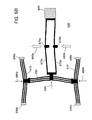
- FIGS 6A and 6B illustrate yet other embodiments wherein the driven arched beams of first and second spaced apart thermal arched beam actuators are themselves coupled together by another driven arched beam(s). These cascaded configurations may be used to obtain extremely large displacements or to obtain other improved performance properties such as lower power usage.
- a first driven arched beam(s) 650 is driven at the end thereof by first and second thermal arched beams 610 and 620 that extend between spaced apart supports 630a, 630b and 640a, 640b on a substrate 600.
- Arching of the first and second thermal arched beams 610 and 620 in the directions shown by displacement arrows 680a and 680b squeezes the ends of the driven arched beams 650a and 650b to cause displacement of the actuated elements 675a and 675b in the directions shown by displacement arrows 690a and 690b.
- a mirror image of this structure is provided, including third and fourth thermal arched beams 610' and 620' and a second driven arched beam(s) 650', with the corresponding elements indicated by prime notation.
- At least one third driven arched beam 675 is coupled between the first and second driven arched beams 650 and 650'. More specifically, the ends of the third driven arched beam(s) 675 are coupled between the intermediate portions of the first and second thermal arched beam(s) 650 and 650'.
- the ends of the third driven arched beam(s) 650a and 650b may be squeezed by a large amount due to the displacement amplification provided by the first and second driven arched beams 650 and 650', to thereby provide a large displacement of contact 670 in the direction shown by arrow 695.
- each of the actuators of Figure 6A may be embodied using any of the previously described embodiments and the third driven arched beam(s) 675a and 675b also may be embodied using any of the previously described embodiments. It also will be understood that not all of thermal arched beams 610, 620, 610' and 620' need be actuated simultaneously.
- Figure 6B is similar to Figure 6A, except it describes a third driven arched beam that is driven at one end only by an H-TAB actuator.
- the other end of the third driven arched beams 675 is fixed by an anchor 640.
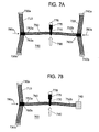
- Figure 7A illustrates embodiments of the present invention that may be used to form a Variable Optical Attenuator (VOA) and/or an optical switch (a binary optical attenuator).
- Figure 7A illustrates an H-TAB VOA that includes at least one first thermal arched beam 710 between first spaced apart supports 730a and 730b on a substrate 700 and at least one second thermal arched beam 720 between second spaced apart supports 740a and 740b on the substrate 700.
- At least one driven arched beam 750 is coupled between the first and second thermal arched beams 710 and 720, for example using couplers 760a and 760b.
- the at least one driven arched beam 750 moves in the direction 790.
- the two thermal arched beams 750 are shown coupled together by a coupler 770.
- a paddle 775 is attached to the coupler 770. It will be understood that the paddle 775 and the coupler 770 may form one integral structure.
- the paddle 775 is oriented so as to selectively cover an end of an optical fiber 778 that passes through the substrate 700, for example orthogonal or at an oblique angle to the substrate face.
- variable or binary optical attenuation of optical radiation through the fiber 778 may be provided.
- VOAs with high precision, low power and/or small footprint may be provided.
- the paddle 775 and coupler 770 may be configured such that attenuation may be provided upon displacement in a direction that is opposite the direction 790.
- FIG. 7B illustrates embodiments of analogous T-TAB VOAs wherein a fixed support 740 is used rather than a second thermal arched beam(s).
- FIGS 8A and 8B illustrate alternative embodiments of H-TAB VOAs and T-TAB VOAs, respectively.
- two ends of optical fibers 878a and 878b extend along the substrate 800 and the integrated paddle/coupler 770 selectively attenuates optical radiation passing between the fiber ends 878a and 878b. It also will be understood that all the other embodiments that are described herein may be used to provide VOAs for one or more fibers.
- H-TAB and T-TAB actuators can provide "out of plane” actuation wherein the driven beams arches in a direction that is nonparallel to the substrate.
- the driven beam includes end portions that move relative to one another to arch the driven beam in a direction that is nonparallel to the substrate in response to the further arching of the thermal arched beam(s) for movement of the driven beam toward or away from the substrate.
- first and second thermal arched beam(s) 910 and 920 are included on a substrate 900 and are supported by first and second pairs of spaced apart supports 930a, 930b and 940a, 940b for actuation in the displacement directions shown by displacement arrows 980a and 980b.
- a driven beam such as a driven arched beam 950 is coupled to the first and second thermal arched beams 910 and 920, for example using couplers 960a and 960b.
- the driven beam 950 preferably is wider than the thermal arched beams 910 and 920 when viewed from above, so that arching along the substrate is not promoted.
- the driven beam 950 preferably is thin in cross-section to promote arching out of the plane of the substrate as shown by displacement indicator 990.
- Figure 9B illustrates a similar T-TAB configuration that uses a fixed support 940 rather than a second thermal arched beam(s) 920.
- Figures 10A-10C are cross-sectional views of Figure 9A along line 10-10' to illustrate the arching of the driven beam 950 out of the plane of the substrate 900.
- the substrate 900 includes an optional trench 905 that can reduce stiction and can provide clearance for the out of plane arched beam 950.
- the driven arched beam 950 is thin in cross-section relative to the thermal arched beams 910 and 920, so that displacement occurs in the displacement direction 990 as shown.
- Figure 10A illustrates arching that may be provided by a continuous driven arched beam 950.
- Figure 10B illustrates arching that may be provided by a stepped arched beam that includes a pair of end sections 950a and 950b and a center section 950c that is offset from the end sections 950a and 950b. If the center section 950c is offset beneath the end sections 950a and 950b, arching toward the substrate 900 may be provided.
- Figure 10C illustrates yet another embodiment wherein the combination of the coupler 960 and a straight beam 950' may provide an equivalent to an arched beam by biasing the beam to arch in the displacement direction 990 as shown.
- FIG 11A describes other embodiments of microelectromechanical actuators according to the present invention.
- a relatively large displacement and relatively small force of a TAB actuator is converted to a relatively large force and relatively small displacement in at least one driven arched beam. Accordingly, the mechanical advantage of the driven arched beam may be reversed compared to Figures 1-10.
- At least one thermal arched beam 1110 extends between spaced apart supports 1130a and 1130b on a substrate 1100. Actuation of the thermal arched beam(s) 1110 causes the intermediate portion thereof, to move in a first direction indicated by displacement arrow 1180.
- the thermal arched beam(s) 1110 is coupled to an intermediate portion of a driven arched beam(s) 1150, for example using a coupler 1160. Accordingly, upon actuation, the end portion(s) of the driven arched beam(s) 1150 are driven against a pair of fixed supports 1192a, 1192b and slide along the fixed supports 1192a, 1192b in the directions shown by displacement arrows 1190a and 1190b.
- Microelectromechanical actuators of Figure 11A may be embodied as a "shorting bar" microrelay.
- the thermal arched beam(s) 1110 is used to drive contacts 1170a and/or 1170b at the ends of a driven arched beam(s) 1150 into a pair of fixed contacts 1192a and 1192b, to which signals may be applied at signal pads 1194a, 1194b.
- the contacts 1170a and 1170b at the end of the driven arched beam(s) 1350 are driven against the rigid contacts 1192a and 1192b and then slide along the rigid contacts 1192a and 1192b along the respective directions 1190a and 1190b.
- the relatively large displacement of the thermal arched beam 1110 can be converted to a relatively large force at the two points of contact between the contacts 1170a and 1170b and the fixed contacts 1192a and 1192b.
- a mechanical stop 1196 may be used to prevent snap-through buckling of the driven arched beams.
- Figure 11B illustrates other embodiments wherein further arching of the thermal arched beam(s) 1110 causes the ends of the driven arched beam(s) 1150 to move toward one another in directions 1190a' and 1190b'.
- Like elements are indicated by prime notation. Many other embodiments may be envisioned.
- microelectromechanical actuators there can be many uses for embodiments of microelectromechanical actuators according to the present invention.
- Optical applications may be envisioned, such as using an H-TAB actuator to drive variable optical attenuators and/or optical crossconnect switching devices.
- Electrical and/or radio frequency applications such as using an H-TAB actuator to drive a microrelay or variable capacitor/inductor also may be provided.
- a thermostat may be provided wherein the thermal arched beam further arches upon heating thereof by ambient heat of an ambient environment in which the microelectromechanical actuator is present.
- Other applications such as using these actuator arrays for microfluidic control or micropneumatic control, may be provided.
- one or more of the driven arched beams may be coupled to other elements, such as relay contacts, optical attenuators, variable circuit elements such as resistors and capacitors, valves and circuit breakers.
- other elements such as relay contacts, optical attenuators, variable circuit elements such as resistors and capacitors, valves and circuit breakers.
Landscapes
- Physics & Mathematics (AREA)
- Electromagnetism (AREA)
- Engineering & Computer Science (AREA)
- Computer Hardware Design (AREA)
- Microelectronics & Electronic Packaging (AREA)
- Micromachines (AREA)
Abstract
Description
As can be seen from Figure 10A, the driven
Claims (10)
- A microelectromechanical actuator comprising:CHARACTERIZED BY:a substrate (100); andan actuator on the substrate that includes a driver beam (110) that moves along the substrate upon actuation of the actuator;a plurality of driven arched beams (150) that are coupled to the driver beam, a respective driven arched beam including end portions that move relative to one another to change the arching of the respective driven arched beam in response to the movement of the driver beam along the substrate, a respective driven arched beam also including a respective actuated element (170) at an intermediate portion thereof between the end portions, wherein a respective actuated element is mechanically coupled to the associated driven archedbeam for movement therewith and is mechanically decoupled from remaining driven arched beams for movement independent thereof.
- A microelectromechanical actuator according to Claim 1 further CHARACTERIZED BY the plurality of driven arched beams comprising first and second driven arched beams (350a, 350b) that extend parallel to one another such that the actuated elements (370a, 370b) that are mechanically coupled to the first and second driven arched beams move in a same direction (390a, 390b) by the movement of the driver beam.
- A microelectromechanical actuator according to Claim 1 further CHARACTERIZED BY the plurality of driven arched beams comprising first and second driven arched beams (250a, 250b) that arch away from one another such that the actuated elements (270a, 270b) that are coupled to the first and second driven arched beams move in opposite directions (290a, 290b) by the movement of the driver beam.
- A microelectromechanical actuator according to Claim 1 further CHARACTERIZED BY the plurality of driven arched beams comprising first and second driven arched beams (150a, 150b) that arch toward one another such that the actuated elements (170a, 170b) that are mechanically coupled to the first and second driven arched beams move in opposite directions (190a, 190b) by the movement of the driver beam.
- A microelectromechanical actuator according to Claims 1, 2, 3 or 4 further CHARACTERIZED BY a trench (105) in the substrate beneath at least one of the plurality of driven arched beams, to reduce stiction between the at least one of the plurality of driven arched beams and the substrate.
- A microelectromechanical actuator according to Claims 1, 2, 3 or 4 further CHARACTERIZED BY at least one of the driven arched beams being arched in a direction that is nonparallel to the substrate.
- A microelectromechanical actuator comprising:CHARACTERIZED BY:a substrate (1100); andan actuator on the substrate that includes a driver beam (1110) that moves along the substrate upon actuation of the actuator;
a driven arched beam (1150) that includes an intermediate portion between end portions thereof, the intermediate portion being coupled to the driver beam, the end portions of the driven arched beam moving relative to one another to change the arching of the driven arched beam in response to the movement of the driver beam along the substrate. - A microelectromechanical actuator according to Claim 7 further CHARACTERIZED BY first and second fixed supports (1192a, 1192b) on the substrate, and wherein the end portions of the driven arched beam are driven against the respective fixed supports and slide along the fixed supports, in response to the movement of the driver.
- A microelectromechanical actuator comprising:CHARACTERIZED BY:a substrate (700); andan actuator on the substrate that includes a driver beam (710) that moves along the substrate upon actuation of the actuator;a driven beam (750) that is coupled to the driver beam, the driven beam including end portions that move relative to one another to arch and move the driven beam along the substrate in response to movement of the driven beam; andan optical attenuator (775) that is coupled to the driven beam and that is arranged to move into an optical path (778) on the substrate in response to movement of the driven beam along the substrate such that the optical attenuator blocks at least a portion of optical radiation in the optical path.
- A microelectromechanical actuator according to Claim 9 wherein the actuator is a first actuator, wherein the driver beam is a first driver beam, the microelectromechanical actuator further CHARACTERIZED BY:a second actuator on the substrate that includes a second driver beam that moves along the substrate upon actuation of the second actuator;a second driven beam that is coupled to the second driver beam, and that moves along the substrate upon actuation of the second actuator; anda third driven beam that is coupled to the first and second driven beams, the third driven beam including end portions that move relative to one another to change the arching of the third driven beam in response to the movement of the first and second driven beams;wherein the optical attenuator is coupled to the third driven beam and is arranged to move into an optical path on the substrate in response to movement of the third driven arched beam along the substrate.
Applications Claiming Priority (2)
| Application Number | Priority Date | Filing Date | Title |
|---|---|---|---|
| US542672 | 2000-04-05 | ||
| US09/542,672 US6360539B1 (en) | 2000-04-05 | 2000-04-05 | Microelectromechanical actuators including driven arched beams for mechanical advantage |
Publications (3)
| Publication Number | Publication Date |
|---|---|
| EP1143467A2 true EP1143467A2 (en) | 2001-10-10 |
| EP1143467A3 EP1143467A3 (en) | 2003-01-29 |
| EP1143467B1 EP1143467B1 (en) | 2004-09-15 |
Family
ID=24164812
Family Applications (1)
| Application Number | Title | Priority Date | Filing Date |
|---|---|---|---|
| EP01302514A Expired - Lifetime EP1143467B1 (en) | 2000-04-05 | 2001-03-19 | Microelectromechanical actuators including driven arched beams for mechanical advantage |
Country Status (7)
| Country | Link |
|---|---|
| US (1) | US6360539B1 (en) |
| EP (1) | EP1143467B1 (en) |
| KR (1) | KR20010095286A (en) |
| CN (1) | CN1316380A (en) |
| CA (1) | CA2340807A1 (en) |
| DE (1) | DE60105479T2 (en) |
| TW (1) | TW508415B (en) |
Cited By (6)
| Publication number | Priority date | Publication date | Assignee | Title |
|---|---|---|---|---|
| WO2002068319A3 (en) * | 2001-02-27 | 2003-08-21 | Litton Systems Inc | Bi-stable micro-actuator and optical switch |
| US6788840B2 (en) | 2001-02-27 | 2004-09-07 | Northrop Grumman Corporation | Bi-stable micro-actuator and optical switch |
| EP1201602A3 (en) * | 2000-10-31 | 2005-02-16 | Microsoft Corporation | Thermal out-of-plane buckle-beam actuator |
| EP1331201A3 (en) * | 2002-01-17 | 2005-02-16 | Microsoft Corporation | Resonant thermal out-of-plane buckle-beam acuator |
| FR2987171A1 (en) * | 2012-02-22 | 2013-08-23 | St Microelectronics Rousset | MECHANICAL NON-RETURN DEVICE INTEGRATED WITH ONE OR MORE POSITIONS, ELECTRICALLY ACTIVABLE |
| WO2015153179A1 (en) * | 2014-04-01 | 2015-10-08 | Agiltron, Inc. | Microelectromechanical displacement structure and method for controlling displacement |
Families Citing this family (29)
| Publication number | Priority date | Publication date | Assignee | Title |
|---|---|---|---|---|
| DE10015598C2 (en) * | 2000-03-29 | 2002-05-02 | Fraunhofer Ges Forschung | Mikroaktoranordnung |
| US7064879B1 (en) | 2000-04-07 | 2006-06-20 | Microsoft Corporation | Magnetically actuated microelectrochemical systems actuator |
| US6902702B1 (en) | 2000-08-16 | 2005-06-07 | University Health Network | Devices and methods for producing microarrays of biological samples |
| US6775048B1 (en) | 2000-10-31 | 2004-08-10 | Microsoft Corporation | Microelectrical mechanical structure (MEMS) optical modulator and optical display system |
| US6594994B2 (en) * | 2001-06-01 | 2003-07-22 | Wisconsin Alumni Research Foundation | Micromechanical actuation apparatus |
| US6804959B2 (en) | 2001-12-31 | 2004-10-19 | Microsoft Corporation | Unilateral thermal buckle-beam actuator |
| US7053519B2 (en) | 2002-03-29 | 2006-05-30 | Microsoft Corporation | Electrostatic bimorph actuator |
| WO2004066326A2 (en) * | 2003-01-17 | 2004-08-05 | The Regents Of The University Of California | Electro-thermally actuated lateral contact microrelay and associated manufacturing process |
| US6985651B2 (en) * | 2003-08-05 | 2006-01-10 | Xerox Corporation | Thermal actuator with offset beam segment neutral axes and an optical waveguide switch including the same |
| US6985650B2 (en) * | 2003-08-05 | 2006-01-10 | Xerox Corporation | Thermal actuator and an optical waveguide switch including the same |
| US6983088B2 (en) * | 2003-08-05 | 2006-01-03 | Xerox Corporation | Thermal actuator and an optical waveguide switch including the same |
| DE602006003737D1 (en) * | 2005-02-23 | 2009-01-02 | Pixtronix Inc | LIGHT MODULATOR AND METHOD FOR THE PRODUCTION THEREOF |
| WO2006110908A1 (en) * | 2005-04-15 | 2006-10-19 | University Of Florida Research Foundation, Inc. | Microactuator having multiple degrees of freedom |
| US7548145B2 (en) * | 2006-01-19 | 2009-06-16 | Innovative Micro Technology | Hysteretic MEMS thermal device and method of manufacture |
| US7944113B2 (en) * | 2006-01-19 | 2011-05-17 | Innovative Micro Technology | Hysteretic MEMS thermal device and method of manufacture |
| US7710574B2 (en) * | 2007-01-23 | 2010-05-04 | Board Of Regents, The University Of Texas System | Devices in miniature for interferometric use and fabrication thereof |
| US20090146773A1 (en) * | 2007-12-07 | 2009-06-11 | Honeywell International Inc. | Lateral snap acting mems micro switch |
| WO2009079460A1 (en) * | 2007-12-14 | 2009-06-25 | University Of Florida Research Foundation, Inc. | Electrothermal microactuator for large vertical displacement without tilt or lateral shift |
| US8232858B1 (en) * | 2008-02-20 | 2012-07-31 | Sandia Corporation | Microelectromechanical (MEM) thermal actuator |
| US8234951B1 (en) * | 2009-05-13 | 2012-08-07 | University Of South Florida | Bistable aerial platform |
| TWI425547B (en) * | 2011-05-06 | 2014-02-01 | 財團法人國家實驗研究院國家晶片系統設計中心 | CMOS microelectromechanical switch structure |
| TWI506661B (en) * | 2013-05-20 | 2015-11-01 | Univ Nat Taiwan | Push-on-push-off bistable switch |
| CN106145027B (en) * | 2015-04-28 | 2018-05-15 | 苏州希美微纳系统有限公司 | A kind of MEMS rotary actuators based on electrothermal drive |
| CN106291915B (en) * | 2015-06-12 | 2019-06-25 | 联想(北京)有限公司 | Control device and method |
| JP2019522570A (en) * | 2016-05-26 | 2019-08-15 | メムズ ドライブ インク. | Impact caging mechanism for MEMS actuator structure |
| JP6953118B2 (en) * | 2016-07-04 | 2021-10-27 | エドワード・パクチャン | MEMS light modulators for displays |
| JP6953117B2 (en) * | 2016-07-04 | 2021-10-27 | エドワード・パクチャン | Light modulators for MEMS displays |
| WO2021011410A1 (en) * | 2019-07-12 | 2021-01-21 | Magic Leap, Inc. | Methods and systems for augmented reality display with dynamic field of view |
| CN116922421B (en) * | 2023-07-19 | 2025-10-28 | 齐鲁工业大学(山东省科学院) | A spatial multistable mechanism |
Family Cites Families (7)
| Publication number | Priority date | Publication date | Assignee | Title |
|---|---|---|---|---|
| US4570139A (en) * | 1984-12-14 | 1986-02-11 | Eaton Corporation | Thin-film magnetically operated micromechanical electric switching device |
| US5226099A (en) * | 1991-04-26 | 1993-07-06 | Texas Instruments Incorporated | Digital micromirror shutter device |
| US5994816A (en) * | 1996-12-16 | 1999-11-30 | Mcnc | Thermal arched beam microelectromechanical devices and associated fabrication methods |
| US5909078A (en) | 1996-12-16 | 1999-06-01 | Mcnc | Thermal arched beam microelectromechanical actuators |
| US5962949A (en) | 1996-12-16 | 1999-10-05 | Mcnc | Microelectromechanical positioning apparatus |
| US5867302A (en) * | 1997-08-07 | 1999-02-02 | Sandia Corporation | Bistable microelectromechanical actuator |
| US6020564A (en) * | 1998-06-04 | 2000-02-01 | Wang Electro-Opto Corporation | Low-voltage long life electrostatic microelectromechanical system switches for radio-frequency applications |
-
2000
- 2000-04-05 US US09/542,672 patent/US6360539B1/en not_active Expired - Lifetime
-
2001
- 2001-03-14 CA CA002340807A patent/CA2340807A1/en not_active Abandoned
- 2001-03-19 TW TW090106327A patent/TW508415B/en not_active IP Right Cessation
- 2001-03-19 EP EP01302514A patent/EP1143467B1/en not_active Expired - Lifetime
- 2001-03-19 DE DE60105479T patent/DE60105479T2/en not_active Expired - Fee Related
- 2001-04-03 KR KR1020010017747A patent/KR20010095286A/en not_active Withdrawn
- 2001-04-05 CN CN01116219A patent/CN1316380A/en active Pending
Cited By (9)
| Publication number | Priority date | Publication date | Assignee | Title |
|---|---|---|---|---|
| EP1201602A3 (en) * | 2000-10-31 | 2005-02-16 | Microsoft Corporation | Thermal out-of-plane buckle-beam actuator |
| WO2002068319A3 (en) * | 2001-02-27 | 2003-08-21 | Litton Systems Inc | Bi-stable micro-actuator and optical switch |
| US6788840B2 (en) | 2001-02-27 | 2004-09-07 | Northrop Grumman Corporation | Bi-stable micro-actuator and optical switch |
| EP1331201A3 (en) * | 2002-01-17 | 2005-02-16 | Microsoft Corporation | Resonant thermal out-of-plane buckle-beam acuator |
| FR2987171A1 (en) * | 2012-02-22 | 2013-08-23 | St Microelectronics Rousset | MECHANICAL NON-RETURN DEVICE INTEGRATED WITH ONE OR MORE POSITIONS, ELECTRICALLY ACTIVABLE |
| US8902600B2 (en) | 2012-02-22 | 2014-12-02 | Stmicroelectronics (Rousset) Sas | Electrically activatable integrated mechanical anti-rollback device with one or more positions |
| WO2015153179A1 (en) * | 2014-04-01 | 2015-10-08 | Agiltron, Inc. | Microelectromechanical displacement structure and method for controlling displacement |
| US10730740B2 (en) | 2014-04-01 | 2020-08-04 | Agiltron, Inc. | Microelectromechanical displacement structure and method for controlling displacement |
| US10752492B2 (en) | 2014-04-01 | 2020-08-25 | Agiltron, Inc. | Microelectromechanical displacement structure and method for controlling displacement |
Also Published As
| Publication number | Publication date |
|---|---|
| KR20010095286A (en) | 2001-11-03 |
| DE60105479T2 (en) | 2005-08-25 |
| US6360539B1 (en) | 2002-03-26 |
| TW508415B (en) | 2002-11-01 |
| DE60105479D1 (en) | 2004-10-21 |
| EP1143467A3 (en) | 2003-01-29 |
| CA2340807A1 (en) | 2001-10-05 |
| CN1316380A (en) | 2001-10-10 |
| EP1143467B1 (en) | 2004-09-15 |
Similar Documents
| Publication | Publication Date | Title |
|---|---|---|
| EP1143467A2 (en) | Microelectromechanical actuators including driven arched beams for mechanical advantage | |
| US6333583B1 (en) | Microelectromechanical systems including thermally actuated beams on heaters that move with the thermally actuated beams | |
| EP1143466B1 (en) | Lockable microelectromechanical actuators using thermoplastic materials, and methods of operating same | |
| US7036312B2 (en) | MEMS actuators | |
| US6351580B1 (en) | Microelectromechanical devices having brake assemblies therein to control movement of optical shutters and other movable elements | |
| US7011288B1 (en) | Microelectromechanical device with perpendicular motion | |
| KR20010050447A (en) | In-plane MEMS thermal actuator and associated fabrication methods | |
| KR101541915B1 (en) | Mems microswitch having a dual actuator and shared gate | |
| EP1095388A1 (en) | Multi-dimensional scalable displacement enabled microelectromechanical actuator structures and arrays | |
| CA2371182A1 (en) | Moveable microelectromechanical mirror structures | |
| US6262512B1 (en) | Thermally actuated microelectromechanical systems including thermal isolation structures | |
| US6608714B2 (en) | Bi-directional, single material thermal actuator | |
| Chen et al. | A new latched 2× 2 optical switch using bi-directional movable electrothermal H-beam actuators | |
| US7116855B2 (en) | Optical shuttle system and method used in an optical switch | |
| US20040183632A1 (en) | Self-retracting fully compliant bistable micromechanism | |
| US7714691B2 (en) | Versatile system for a locking electro-thermal actuated MEMS switch | |
| WO2003003396A1 (en) | Self-retracting fully compliant bistable micromechanism | |
| JP2004530150A (en) | Bistable microactuator and optical switch | |
| JP2002219694A (en) | Semiconductor micro actuator, and manufacturing method therefor | |
| US20090033454A1 (en) | MEMS actuators with even stress distribution |
Legal Events
| Date | Code | Title | Description |
|---|---|---|---|
| PUAI | Public reference made under article 153(3) epc to a published international application that has entered the european phase |
Free format text: ORIGINAL CODE: 0009012 |
|
| AK | Designated contracting states |
Kind code of ref document: A2 Designated state(s): AT BE CH CY DE DK ES FI FR GB GR IE IT LI LU MC NL PT SE TR |
|
| AX | Request for extension of the european patent |
Free format text: AL;LT;LV;MK;RO;SI |
|
| RAP1 | Party data changed (applicant data changed or rights of an application transferred) |
Owner name: JDS UNIPHASE CORPORATION |
|
| PUAL | Search report despatched |
Free format text: ORIGINAL CODE: 0009013 |
|
| AK | Designated contracting states |
Designated state(s): AT BE CH CY DE DK ES FI FR GB GR IE IT LI LU MC NL PT SE TR |
|
| AX | Request for extension of the european patent |
Extension state: AL LT LV MK RO SI |
|
| RIC1 | Information provided on ipc code assigned before grant |
Ipc: 7H 01H 1/00 A Ipc: 7G 02B 6/26 B |
|
| RAP1 | Party data changed (applicant data changed or rights of an application transferred) |
Owner name: MEMSCAP S.A. |
|
| 17P | Request for examination filed |
Effective date: 20030729 |
|
| AKX | Designation fees paid |
Designated state(s): CH DE FR GB LI |
|
| 17Q | First examination report despatched |
Effective date: 20031031 |
|
| GRAP | Despatch of communication of intention to grant a patent |
Free format text: ORIGINAL CODE: EPIDOSNIGR1 |
|
| GRAS | Grant fee paid |
Free format text: ORIGINAL CODE: EPIDOSNIGR3 |
|
| GRAA | (expected) grant |
Free format text: ORIGINAL CODE: 0009210 |
|
| AK | Designated contracting states |
Kind code of ref document: B1 Designated state(s): CH DE FR GB LI |
|
| PG25 | Lapsed in a contracting state [announced via postgrant information from national office to epo] |
Ref country code: CH Free format text: LAPSE BECAUSE OF FAILURE TO SUBMIT A TRANSLATION OF THE DESCRIPTION OR TO PAY THE FEE WITHIN THE PRESCRIBED TIME-LIMIT Effective date: 20040915 Ref country code: LI Free format text: LAPSE BECAUSE OF FAILURE TO SUBMIT A TRANSLATION OF THE DESCRIPTION OR TO PAY THE FEE WITHIN THE PRESCRIBED TIME-LIMIT Effective date: 20040915 |
|
| REG | Reference to a national code |
Ref country code: CH Ref legal event code: EP Ref country code: GB Ref legal event code: FG4D |
|
| REG | Reference to a national code |
Ref country code: IE Ref legal event code: FG4D |
|
| REF | Corresponds to: |
Ref document number: 60105479 Country of ref document: DE Date of ref document: 20041021 Kind code of ref document: P |
|
| PGFP | Annual fee paid to national office [announced via postgrant information from national office to epo] |
Ref country code: GB Payment date: 20050316 Year of fee payment: 5 |
|
| PGFP | Annual fee paid to national office [announced via postgrant information from national office to epo] |
Ref country code: DE Payment date: 20050317 Year of fee payment: 5 |
|
| REG | Reference to a national code |
Ref country code: CH Ref legal event code: PL |
|
| ET | Fr: translation filed | ||
| PLBE | No opposition filed within time limit |
Free format text: ORIGINAL CODE: 0009261 |
|
| STAA | Information on the status of an ep patent application or granted ep patent |
Free format text: STATUS: NO OPPOSITION FILED WITHIN TIME LIMIT |
|
| 26N | No opposition filed |
Effective date: 20050616 |
|
| PG25 | Lapsed in a contracting state [announced via postgrant information from national office to epo] |
Ref country code: GB Free format text: LAPSE BECAUSE OF NON-PAYMENT OF DUE FEES Effective date: 20060319 |
|
| PG25 | Lapsed in a contracting state [announced via postgrant information from national office to epo] |
Ref country code: DE Free format text: LAPSE BECAUSE OF NON-PAYMENT OF DUE FEES Effective date: 20061003 |
|
| GBPC | Gb: european patent ceased through non-payment of renewal fee |
Effective date: 20060319 |
|
| REG | Reference to a national code |
Ref country code: FR Ref legal event code: PLFP Year of fee payment: 16 |
|
| REG | Reference to a national code |
Ref country code: FR Ref legal event code: PLFP Year of fee payment: 17 |
|
| REG | Reference to a national code |
Ref country code: FR Ref legal event code: PLFP Year of fee payment: 18 |
|
| PGFP | Annual fee paid to national office [announced via postgrant information from national office to epo] |
Ref country code: FR Payment date: 20200326 Year of fee payment: 20 |