BACKGROUND OF THE INVENTION
The present invention relates to a method for
recording a large amount of information on a magnetic
recording medium at one time, and in particular, to a
method for transferring a recording information to a
magnetic recording medium of large capacity and high
recording density.
With rapid development and progress in the utilization
of digital image, amount of information to be handled in
personal computers and other devices has extensively
increased. Because of the increase of the amount of
information, there are now strong demands on a magnetic
recording medium, which has larger capacity to record the
information and can be manufactured at low cost and
requires shorter time for writing and reading operations.
In a high density recording medium such as hard disk
or in a high density floppy disk type magnetic recording
medium represented by ZIP (Iomega Inc.), information
recording area has narrower track compared with the floppy
disk now commonly used. In order that magnetic head can
scan over narrow track width and signals can be recorded or
reproduced with high S/N ratio, it is necessary to perform
accurate scanning by the tracking servo technique.
In a large capacity magnetic recording medium such as
a hard disk or a removable type magnetic recording medium,
servo signal for tracking or address information signal,
reproduction clock signal, etc. are recorded with a certain
spacing between them within one turn of the disk. This is
the so-called pre-format.
By reading this pre-formatted signal and by correcting
its own position, the magnetic head can run accurately on
the track.
In the mode of pre-formatting currently in practice,
disks are recorded one by one and track by track using a
special-purpose servo recorder. However, there are
problems in that the servo recorder are expensive and long
time is required for the preparation of the pre-format and
this means longer time for manufacture and higher
manufacturing cost.
In this respect, a method has been proposed to perform
magnetic transfer without carrying out pre-format for each
track. For example, a transfer technique is described in
Japanese Patent Publications Laid-Open 63-183623, 10-40544,
and 10-269566. However, none of these inventions provides
a proposal suitable for practical applications. There has
been no disclosure on concrete means or conditions such as
the condition of magnetic field to be applied at the
magnetic transfer in the method for magnetic transfer or
the means for generating the magnetic field.
To solve the problems as described above, the
following method has been proposed in Japanese Patent
Publications Laid-Open 63-183623 and 10-40544: On the
surface of the substrate, surface irregularities (i.e.
recesses and projections; concave portions and convex
portions) corresponding to information signals are formed.
The surface of the master carrier for magnetic transfer
where ferromagnetic thin film is formed at least on the
projections is brought into contact with the surface of
sheet-type or disk-type magnetic recording medium where
ferromagnetic thin film or ferromagnetic powder coating
layer is formed. Or, AC bias magnetic field or DC magnetic
field is applied to excite ferromagnetic material which
constitutes the surface of the projections. As a result,
magnetized pattern to match the surface irregularities is
recorded on the magnetic recording medium.
According to this method, the surface of the projected
portions of the master carrier for magnetic transfer is
brought closely together to the magnetic recording medium
to be pre-formatted, i.e. the slave medium, and the
ferromagnetic material which constitutes the projected
portions is excited. As a result, the desired format is
formed on the slave medium. By this method, recording can
be carried out statically without changing relative
positions of the master carrier for magnetic transfer and
the slave medium, and accurate pre-format recording can be
performed. Also, the time required for the recording is
very short. Specifically, in the method for recording from
the magnetic head as described above, the time of several
minutes to several tens of minutes is normally required,
while magnetic transfer can be completed within one second
regardless of the recording capacity or recording density
in this magnetic transfer method.
Now, description will be given on the transfer of
pattern for pre-format in the master carrier for magnetic
transfer referring to Fig. 1. Fig. 1 (A) is a schematical
plan view to explain magnetic layer surface of the master
carrier for magnetic transfer, and Fig. 1 (B) is a cross-sectional
view to explain the process of transfer.
On a certain area of the track of the master carrier 1
for magnetic transfer, a pre-format region 2 and a data
region 3 where patterns of servo signals and address signal
for tracking to be transferred are formed. By bringing the
master carrier 1 for magnetic transfer and the slave medium
4 closely together and by applying an external magnetic
field 6 for transfer in track direction 5, the pre-format
information can be transferred to the slave medium as a
recording information 7. Thus, the slave medium can be
manufactured with high efficiency.
However, it has been made clear that, when magnetic
transfer is performed according to this method, the quality
of information signal may be deteriorated, and that servo
action may be inaccurate.
SUMMARY OF THE INVENTION
It is an object of the present invention to provide a
method and an apparatus for stable magnetic transfer by
bringing a master carrier for magnetic transfer and a slave
medium closely together and by transferring a pre-format
pattern through application of an external magnetic field
in order to prevent inaccurate servo operation of the slave
medium.
The present invention provides a method for magnetic
transfer by bringing a master carrier for magnetic transfer
with a slave medium and by applying magnetic field for
transfer, said master carrier having a magnetic layer on
surface of a substrate corresponding to an information
signal, and said slave medium comprising a magnetic
recording medium where the information is to be transferred,
said method comprising the steps of:
Further, the present invention provides a method for
magnetic transfer by bringing a master carrier for magnetic
transfer with a slave medium and by applying magnetic field
for transfer, said master carrier having a magnetic layer
on surface of a substrate corresponding to an information
signal, and said slave medium comprising a magnetic
recording medium where the information is to be transferred,
said method comprising the steps of:
Also, the present invention provides a method for
magnetic transfer as described above, wherein, when said
permanent magnets each having magnetic field symmetrical to
the axis of the magnetic pole are arranged at least on one
of upper or lower surfaces of the slave medium with the
axis of the magnetic pole running in parallel to the
surface of the slave medium, the magnetic field intensity
distribution in track direction of the magnetic field
generated is such that there is at least one point where
the magnetic field intensity is higher than the coercive
force Hcs of the slave medium on a position in track
direction.
Further, the present invention provides a method for
magnetic transfer as described above, wherein, when said
permanent magnets each having magnetic field symmetrical to
the axis of the magnetic pole are arranged at least on one
of upper or lower surfaces of the slave medium with the
axis of the magnetic pole running in parallel to the
surface of the slave medium, the magnetic field intensity
distribution in track direction of the magnetic field
generated is such that magnetic field intensity higher than
the coercive force Hcs of the slave medium is present only
in one direction on a position in track direction, and the
magnetic field intensity in reverse direction is lower than
the coercive force Hcs of the slave medium at any position
in any track direction.
Also, the present invention provides a method for
magnetic transfer as described above, wherein, when said
permanent magnets each having magnetic field symmetrical to
the axis of the magnetic pole are arranged at least on one
of upper or lower surfaces of the slave medium with the
axis of the magnetic pole running in parallel to the
surface of the slave medium, the magnetic field intensity
distribution in track direction of the magnetic field
generated is such that magnetic field intensity higher than
the maximum value of the optimal transfer magnetic field
intensity range is not present at any position in any track
direction, magnetic field intensity within the optimal
transfer magnetic field intensity range is present at least
at one point in one track direction, and magnetic field
intensity in track direction reverse thereto is lower than
the minimum value of the optimal transfer magnetic field
intensity range at any position in any track direction.
Further, the present invention provides a method for
magnetic transfer as described above, wherein the optimal
transfer magnetic field intensity is 0.6 x Hcs to 1.3 x Hcs
with respect to the coercive force Hcs of the slave medium.
Also, the present invention provides an apparatus for
magnetic transfer by bringing a master carrier for magnetic
transfer and a slave medium closely together and by
applying magnetic field for transfer, said master carrier
having a magnetic layer on surface of a substrate
corresponding an information signal, and said slave medium
comprising a magnetic recording medium where the
information is to be transferred, said apparatus comprising
initial DC magnetizing means for arranging permanent
magnets each having magnetic field symmetrical to the axis
of the magnetic pole at least on one of upper or lower
surfaces of the slave medium with the axis of the magnetic
pole running in parallel to the surface of the slave medium,
for rotating the slave medium or the permanent magnet in
track direction, and for applying magnetic field in track
direction on the surface of the slave medium to perform
initial DC magnetization of the slave medium in advance in
track direction, combining means for combining the master
carrier for magnetic transfer with the slave medium
processed by said initial DC magnetization, and transfer
magnetic field applying means for applying magnetic field
for transfer in track direction reverse to the direction of
the initial DC magnetization on the surface of the slave
medium.
Further, the present invention provides an apparatus
for magnetic transfer by bringing a master carrier for
magnetic transfer and a slave medium closely together and
by applying magnetic field for transfer, said master
carrier having a magnetic layer on surface of a substrate
corresponding an information signal, and said slave medium
comprising a magnetic recording medium where the
information is to be transferred, said apparatus comprising
initial DC magnetizing means for applying magnetic field in
track direction on the surface of the slave medium and for
performing initial DC magnetization in advance in track
direction of the slave medium, combining means for
combining the master carrier for magnetic transfer with the
slave medium processed by said initial DC magnetization,
and transfer magnetic field applying means for arranging
permanent magnets each having magnetic field symmetrical to
the axis of the magnetic pole at least on one of upper or
lower surfaces of the slave medium with the axis of the
magnetic pole running in parallel to the surface of the
slave medium, for rotating said permanent magnets or the
collective unit comprising said master carrier for magnetic
transfer combined with said slave medium in track direction,
and for applying magnetic field for transfer in track
direction reverse to the direction of the initial DC
magnetization.
Also, the present invention provides an apparatus for
magnetic transfer as described above, wherein, when said
permanent magnets each having magnetic field symmetrical to
the axis of the magnetic pole are arranged at least on one
of upper or lower surfaces of the slave medium with the
axis of the magnetic pole running in parallel to the
surface of the slave medium, magnetic field intensity
distribution in track direction of the magnetic field
generated is such that magnetic field intensity higher than
the coercive force Hcs of the slave medium is present at
least at one point on a position in track direction.
Further, the present invention provides an apparatus
for magnetic transfer as described above, wherein, when
said permanent magnets each having magnetic field
symmetrical to the axis of the magnetic pole are arranged
at least on one of upper or lower surfaces of the slave
medium with the axis of the magnetic pole running in
parallel to the surface of the slave medium, magnetic field
intensity distribution in track direction of the magnetic
field generated is such that magnetic field intensity
higher than the coercive force Hcs of the slave medium is
present only in one direction at a position in track
direction, and magnetic field intensity in reverse
direction is lower than the coercive force Hcs of the slave
medium at any position in track direction.
Also, the present invention provides an apparatus for
magnetic transfer as described above, wherein, when said
permanent magnets each having magnetic field symmetrical to
the axis of the magnetic pole are arranged at least on one
of upper or lower surfaces of the slave medium with the
axis of the magnetic pole running in parallel to the
surface of the slave medium, magnetic field intensity
distribution in track direction of the magnetic field
generated is such that magnetic field intensity higher than
the maximum value of the optimal transfer magnetic field
intensity range is not present at any position in any track
direction, magnetic field intensity within the optimal
transfer magnetic field intensity range is present at least
at one point in one track direction, and magnetic field
intensity in track direction reverse thereto is lower than
the minimum value of the optimal transfer magnetic field
intensity range at any position in any track direction.
Further, the present invention provides an apparatus
for magnetic transfer as described above, wherein the
optimal transfer magnetic field intensity is 0.6 x Hcs to
1.3 x Hcs with respect to the coercive force Hcs of the
slave medium.
BRIEF DESCRIPTION OF THE DRAWINGS
Fig. 1 represents drawings to explain transfer of a
pattern for pre-format on a master carrier for magnetic
transfer;
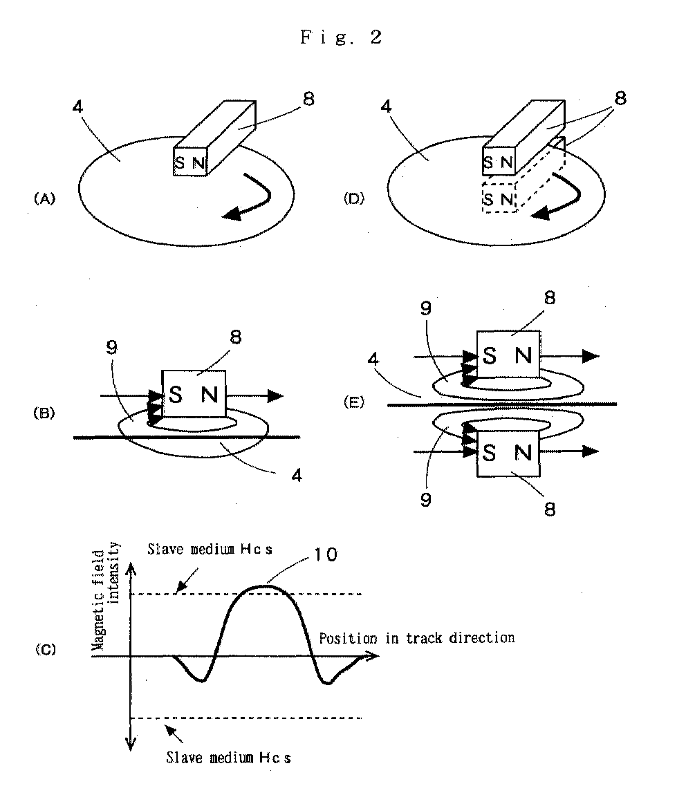
Fig. 2 represents drawings to explain a method for
applying magnetic field using permanent magnets each
directed in lateral direction; and
Fig. 3 represents drawings to explain a method to
transfer a pattern from a master carrier for magnetic
transfer to a slave medium.
DESCRIPTION OF THE PREFERRED EMBODIMENT
When a master carrier for magnetic transfer and a
slave medium are brought closely together and a magnetic
field for transfer is applied from outside, magnetic
transfer operation is unstable and a portion with signals
of poor quality is produced as the result of transfer.
Having found that the quality of signals is decreased
because the magnetic field applied at the time of transfer
is not adequate, the present inventors have conceived the
present invention.
In the magnetic transfer from the master carrier for
magnetic transfer to the slave medium, it has been believed
in the past that, when an external magnetic field higher
than the coercive force Hcs of the slave medium is applied,
the slave medium is magnetized all in applied direction,
and this is the reason why the pattern to be transferred is
not recorded. For example, in Japanese Patent Publication
Laid-Open 10-40544, it is described in the paragraph 0064
that it is preferable to have coercive force equal to or
lower than the coercive force of the magnetic recording
medium.
However, the present inventors have found the
following principle after elaborate study. The principle
of magnetic transfer according to the present system is as
follows: As shown in Fig. 1, in a convex portion of a
magnetic layer of a master carrier 1 for magnetic transfer,
which is substantially in contact with a slave medium 4, an
external magnetic field 6 for transfer is turned to a
magnetic field 6a which is absorbed to the convex portion,
and the recordable magnetic field intensity is not attained
on the magnetic layer of the slave medium 4 in contact.
However, on the magnetic layer of the slave medium 4
corresponding to a concave portion of the master carrier 1
for magnetic transfer not in contact with the slave medium
4, the recordable magnetic field intensity is attained. As
shown by reference numeral 7 in the figure, magnetization
occurs in a direction of the external magnetic field 6 for
transfer, and a pattern for pre-format of the master
carrier 1 for magnetic transfer can be transferred to the
slave medium 4 as a recording information 7.
Therefore, when transfer is performed from the master
carrier for magnetic transfer to the slave medium, in the
portion in contact with the slave medium, most of the
magnetic field enters the pattern portion of the master
carrier for magnetic transfer, and it appears that no
inversion occurs even when transfer magnetic field higher
than the coercive force Hcs of the slave medium is applied.
By applying magnetic field for transfer having intensity in
specific relation to the coercive force Hcs of the slave
medium, it is possible to obtain a slave medium with the
signal of high quality.
In order to achieve clear and distinct transfer in any
type of pattern, initial DC magnetization should be
performed on the slave medium in advance with sufficiently
high magnetic field to magnetize to higher than the
coercive force Hcs, or more preferably, to more than 1.2
times of Hcs. And magnetic field for transfer with
specific intensity, i.e. a magnetic field within optimal
transfer magnetic field intensity range, should be applied.
The preferable magnetic field for transfer is given as:
0.6 × Hcs ≦ Magnetic field for transfer ≦ 1.3 × Hcs
It should be applied in a direction reverse to the
direction of the initial DC magnetization.
More preferably, the magnetic field for transfer has
coercive force of 0.8 - 1.2 Hcs, or most preferably, 1 -
1.1 Hcs.
The magnetic recording medium for performing pre-format
for servo is a disk-type recording medium, and
information is recorded along a track, which is formed
concentrically from the center of rotation. To apply the
magnetic field to transfer a radial pattern in the disk-type
magnetic recording medium as described above, the
magnetic field is applied in the direction of the track on
the slave medium surface, i.e. in tangential direction of a
circular arc at a position in arbitrary track direction,
and initial DC magnetization is performed in track
direction of the slave medium.
Next, the master carrier for magnetic transfer and the
slave medium processed by the initial DC magnetization are
brought closely together, and the magnetic field for
transfer is applied in the direction of track on the slave
medium surface. In this case, the direction of the initial
DC magnetization when magnetic field is applied in the
direction of track on the slave medium must be reverse to
the direction of the magnetic field for transfer applied
for magnetic transfer on the slave medium surface.
Therefore, in order to apply the magnetic field under
the above condition for applying magnetic field all over
the entire surface of the disk-type medium, a magnetic
field of such magnetic field intensity distribution that
magnetic field intensity is higher than the coercive force
Hcs of the slave medium at least at one point on a position
in track direction is generated on a part of the track
direction. By rotating the slave medium or the magnetic
field by one turn in the track direction, the initial DC
magnetization can be achieved.
Also, a magnetic field with such magnetic field
intensity distribution is generated on a portion in the
track direction that it has a portion with magnetic field
intensity of higher than the coercive force Hcs of the
slave medium only in one direction at a position in the
track direction and that magnetic field intensity in
reverse direction is lower than the coercive force Hcs of
the slave medium at any position of the track direction.
By rotating the slave medium or the magnetic field by one
turn in the track direction, a magnetic field for initial
DC magnetization can be applied in the track direction of
the slave medium in advance.
Further, a magnetic field with such magnetic field
intensity distribution is generated on a portion of the
track direction that magnetic field intensity higher than
the maximum value of the optimal transfer magnetic field
intensity range is not present at any position in the track
direction and the portion with magnetic field within the
optimal transfer magnetic field intensity range is present
at least at one point in one track direction and magnetic
field intensity reverse to the track direction is lower
than the minimum value in the optimal transfer magnetic
intensity range at any position of the track direction.
The master carrier for magnetic transfer and the slave
medium subjected to the initial DC magnetization are
brought closely together, and this is rotated in the track
direction or the magnetic field is rotated in the track
direction. Thus, by applying the magnetic field for
transfer in the track direction on the slave medium surface,
this can be accomplished.
The permanent magnet used for the initial DC
magnetization and magnetic transfer is preferably in such
size as to be equal to or longer than the distance from a
track on one end of the slave medium to a track on the
other end. In case of a disk-type slave medium, it is
preferable that it is in such size as to be equal to or
longer than the radial distance from the outermost track to
the innermost track of the slave medium. When a permanent
magnet of such size is used, it is possible to apply
uniform magnetic field on the slave medium surface simply
by moving the slave medium or the closely fitted group or
the collective unit of the slave medium and the master
carrier for magnetic transfer or the permanent magnet in
one direction all over the total length of the track or by
rotating by one turn.
Also, the magnetic field intensity to be applied using
the permanent magnet must be uniform at any position all
over the track. Its variation is preferably within ±5% at
any position over the entire track, or more preferably
within ±2.5%.
In the following, description will be given on a
method for transfer and an apparatus for transfer.
Fig. 2 represents drawings to explain a method for
applying magnetic field using permanent magnets each
directed in lateral direction. Fig. 2 (A) shows an
example where a single permanent magnet 8 having magnetic
field symmetrical to the axis of the magnetic pole is
arranged on upper surface of a slave medium 4 with the axis
of the magnetic pole running in parallel to the surface of
the slave medium 4 and the slave medium 4 is rotated.
From a single permanent magnet 8 disposed on the upper
surface of the slave medium 4, a magnetic field 9 is
applied as shown in Fig. 2 (B) to the surface of the slave
medium 4.
Fig. 2 (C) is a diagram showing magnetic field
intensity to be applied on the slave medium. In the
magnetic field applied on the slave medium, a peak value 10
higher than the coercive force Hcs of the slave medium is
present. By rotating the slave medium or the magnet,
initial DC magnetization can be performed on the slave
medium.
Fig. 2 (D) shows an example where permanent magnets 8
each having magnetic field symmetrical to the axis of the
magnetic pole are arranged on upper and lower surfaces of
the slave medium 4 respectively with the axis of the
magnetic pole running in parallel to the surface of the
slave medium 4 and with direction of the axis of the
magnetic pole of each of the magnets aligned in the same
direction, and the slave medium 4 is rotated. From each
of the permanent magnets 8 arranged on upper and lower
surfaces of the slave medium 4 respectively, a magnetic
field 9 is applied to the surface of the slave medium 4 as
shown in Fig. 2 (E).
Fig. 3 represents drawings to explain a method for
transferring a pattern from the master carrier for magnetic
transfer to the slave medium.
Fig. 3 (A) is a drawing to explain application of
magnetic field to a collective unit comprising the slave
medium and the master carrier for magnetic transfer. Fig.
3 (B) is a diagram showing intensity of magnetic field
given by the application of the magnetic field of Fig. 3
(A).
On the surface of a collective unit 11 combining the
slave medium 4 closely together with the master carrier 1
for magnetic transfer, a single permanent magnet 8 is
arranged, which has magnetic field symmetrical to the axis
of the magnetic field and capable to apply a magnetic field
higher than the coercive force Hcs of the slave medium in
track direction. By applying a magnetic field 12 and by
rotating at least one of the collective unit 11 or the
permanent magnet 8 in track direction with respect to the
central axis of the collective unit 11, a magnetic field in
a direction reverse to the direction of the initial DC
magnetization is applied to the entire surface of the
collective unit 11.
In the applied magnetic field, a peak value 13 with
lower intensity gives no influence on the transfer of the
pattern from the master carrier for magnetic transfer to
the slave medium. Only a peak value 14 with higher
intensity contributes to the magnetic transfer.
Also, by applying a magnetic field within the optimal
transfer magnetic field intensity range from the master
carrier for magnetic transfer to the slave medium, the peak
value 14 with higher intensity can provide a good pattern
regardless of the configuration of the pattern.
Fig. 3 (C) shows a condition where permanent magnets 8
are arranged, each of which has a magnetic field
symmetrical to the axis of the magnetic pole disposed on
both surfaces of the collective unit 11, each of said
permanent magnets being able to apply a magnetic field
higher than the coercive force Hcs of the slave medium in
track direction, and a magnetic field 12 is applied.
Under this condition, by rotating at least one of the
collective unit 11 or the permanent magnets 8 in track
direction with respect to the central axis of the
collective unit 11, a magnetic field reverse to the
direction of the initial DC magnetization is applied to the
entire surface of the collective unit 11, and a peak value
with higher intensity of the magnetic field contributes to
the magnetic transfer.
In the apparatus used in the method for magnetic
transfer as shown in Fig. 2 and Fig. 3, there is provided a
mechanism for adjusting a distance between the slave medium
surface and the permanent magnet as desired. By adjusting
the distance between the slave medium and the permanent
magnet, it is possible to obtain the magnetic field
intensity as desired on the surface of the slave medium.
Now, description will be given on a method to
manufacture the master carrier for magnetic transfer to be
used in the magnetic transfer of the present invention.
As a substrate for the master carrier for magnetic
transfer, a planar member with flat and smooth surface,
which is made of silicon, quartz plate, glass, non-magnetic
metal such as aluminum or alloy, ceramics, synthetic resin,
etc., and which has enough resistance to processing
environment such as temperature in etching and film forming
processes may be used.
On a substrate with flat and smooth surface,
photoresist is coated, and light exposure or development is
performed using a photo mask to match the pattern of pre-format.
Or, the photoresist is directly marked, and a
pattern corresponding to the pre-format information is
formed.
Next, in the etching process, etching of the substrate
is performed corresponding to the pattern by etching means
such as reactive etching, physical etching using argon
plasma, or etching using liquid.
The depth of the hole to be formed by the etching
should be a depth corresponding to thickness of a magnetic
layer formed as a transfer information recording portion.
It is preferably 20 - 1000 nm. If it is too thick,
spreading width of the magnetic field becomes too large,
and this is not desirable.
The holes to be formed have preferably uniform depth
so that bottom surface can be formed with a surface plane
which runs in parallel to the surface of the substrate.
Also, the hole has preferably such a shape that its
cross-section in the track direction perpendicular to the
surface is of rectangular shape.
Next, the magnetic material is processed by vacuum
film forming means such as vacuum deposition method,
sputtering method, ion plating method, and a film of
magnetic material is formed up to the surface of the
substrate in thickness to correspond to the formed hole.
Magnetic characteristics of the transfer information
recording portion are as follows: coercive force (Hcs) not
more than 2500 Oe, or more preferably, 5 - 1500 Oe;
saturation magnetic flux density (Bs) not less than 0.3 T
(Tesla), or more preferably, not less than 0.5 T.
Then, photoresist is removed by lift-off method. The
surface is polished, and burrs are removed if any, and the
surface is flattened.
In the above, description has been given on the method
to form holes on the substrate and to form a film of
magnetic material in the holes thus formed. It may be
designed in such manner that the film of magnetic material
is formed at predetermined points on the substrate by
photo-fabrication method to make convex portions on the
transfer information recording portion, and non-magnetic
material is the formed in film or is filled between the
convex portions, and the surface may be made on the same
level as the non-magnetic material portion of the transfer
information recording portion.
As the magnetic material to be used in the magnetic
layer, cobalt, iron or their alloys having high magnetic
flux density may be used. More concretely, Co, CoPtCr,
CoCr, CoPtCrTa, CoPtCrNbTa, CoCrB, CoNi, Fe, FeCo, FePt,
etc. may be used.
The thickness of the magnetic layer is preferably 20 -
1000 nm, or more preferably, 30 - 500 nm. If it is too
thick, resolution of recording is decreased.
In particular, it is preferable for the purpose of
providing clear transfer that magnetic flux density is high
and it is in the same direction as the slave medium, e.g.
in intra-surface direction in case of intra-surface
recording, and to have magnetic anisotropy in vertical
direction in case of vertical recording. It is preferable
that the magnetic material has a structure of fine magnetic
particles or amorphous structure because sharp edge can be
produced.
In order to provide magnetic anisotropy on the
magnetic material, it is preferable to have a non-magnetic
underlayer, and crystal structure and lattice constant
should be the same as those of the magnetic layer. More
concretely, Cr, CrTi, CoCr, CrTa, CrMo, NiAl, Ru, etc. may
be used to form the film by sputtering.
A protective film such as a diamond-like carbon film
may be formed on the magnetic layer, and lubricant may be
provided. As the protective film, it is more preferable
that diamond-like carbon film of 5 - 30 nm and lubricant
are present. The reason why lubricant must be provided is
as follows: When deviation is caused during the contact
process with the slave medium and this deviation is to be
corrected, friction occurs, and if there is no lubricant
layer, durability may be decreased.
The master carrier for magnetic transfer according to
the present invention can be used not only in the transfer
of magnetic recording information to a disk-type magnetic
recording medium such as hard disk, large capacity
removable type magnetic recording medium, etc. but also in
the transfer of magnetic recording information to a card-type
magnetic recording medium or a tape-type magnetic
recording medium.
[Embodiments]
In the following, description will be given in detail
on the present invention by referring to examples.
[Example 1 and Comparative example 1]
(Preparation of master carrier for magnetic transfer)
In a vacuum film-making apparatus, pressure was
reduced to 10-7 Torr at room temperature, and argon was
then introduced to turn the pressure to 3 × 10⁻³ Torr.
Then, a film of FeCo of 200 nm in thickness was formed on a
silicon substrate, and this was used as a disk-type master
carrier for magnetic transfer of 3.5 inches in diameter.
It had coercive force Hc of 100 Oe and magnetic flux
density (Ms) of 23000 Gauss.
A disk-like pattern was formed by radial lines extending
from the center of the disk to a position of 20 - 40 mm in
radial direction with equal spacing of 10 µ in width. The
spacing of the lines was set to 10 µm at the innermost
position, i.e. 20 mm in radial direction.
(Preparation of the slave medium)
In a vacuum film-making apparatus, pressure was
reduced to 10-7 Torr at room temperature, and argon was
then introduced to turn the pressure to 3 × 10⁻³ Torr. Then,
a glass plate was heated up to 200°C, and a disk-type
magnetic recording medium of 3.5 inches in diameter was
prepared, which had CoCrPt of 25 nm, Ms of 4500 Gauss, and
coercive force (Hcs) of 2500 Oe.
(Initial DC magnetization method)
Permanent magnets were arranged on both surfaces of
the slave medium respectively as shown in Fig. 2 so that
peak magnetic field intensity on the surface of the slave
medium was to be 5000 Oe, i.e. two times as much as the
coercive force Hcs of the slave medium, and initial DC
magnetization of the slave medium was performed.
(Magnetic transfer test method)
The slave medium under initial DC magnetization and
the master carrier for magnetic transfer were brought
closely together. Using an apparatus with the permanent
magnets arranged on both surfaces as shown in Fig. 3(C),
magnetic field was applied in reverse direction to the
magnetization of the slave medium, and magnetic transfer
was performed. To bring the master carrier for magnetic
transfer and the slave medium closely together, these were
squeezed with a rubber plate interposed between them, and
pressure was applied on an aluminum plate.
(Method to evaluate electromagnetic transfer
characteristics)
An electromagnetic transfer characteristics measuring
system (manufactured by Kyodo Electronics; SS-60) was used
to evaluate transfer signal of the slave medium. An MR
head with the following performance data was used:
reproducing head gap 0.33 µ m; reproduction track width 2.6
µm; recording head gap 0.4 µm; and recording track width
3.5 µm.
Reading signal was processed by a spectro-analyzer for
frequency analysis, and a difference (C/N) between peak
intensity of primary signal (C) and extrapolated medium
noise (N) was determined. In the values of C/N at each
magnetic field intensity, relative value of ΔC/N was
evaluated with the maximum value at 0 dB. The results are
shown in Table 1. When the value of C/N was not more than
-20 dB, signal quality of magnetic transfer did not reach
the level for practical use, and this was indicated with
the mark *.
| Hcs of slave medium: 2500 Oe |
| Peak intensity of magnetic field for transfer (Oe) | Ratio to Hcs | ΔC/N (dB) |
| 750 | 0.3 | * |
| 1,250 | 0.5 | -10.2 |
| 1,500 | 0.6 | -4.3 |
| 2,000 | 0.8 | -1.7 |
| 2,250 | 0.9 | -0.3 |
| 2,500 | 1.0 | 0.0 |
| 2,750 | 1.1 | -0.2 |
| 3,000 | 1.2 | -1.4 |
| 3,250 | 1.3 | -3.8 |
| 3,500 | 1.4 | -9.6 |
| 3,750 | 1.5 | -15.8 |
| 4,000 | 1.6 | * |
| 5,000 | 2.0 | * |
To a slave medium having coercive force (Hcs) of 2500
Oe, magnetic transfer was carried out by the same procedure
as in Example 1 except that initial DC magnetization of the
slave medium was performed with peak magnetic field
intensity of 3000 Oe, i.e. magnetic field intensity 1.2
times as high as the coercive force (Hcs) of the slave
medium. Then, the slave medium under initial DC
magnetization and the master carrier for magnetic transfer
were brought closely together and magnetic transfer was
performed. The magnetic transfer pattern was developed by
the same procedure as in Example 1, and measurement was
made. The results are summarized in Table 2. The peak
intensity of the magnetic field for transfer shows a peak
value in the magnetic field intensity distribution shown in
Fig. 3.
| Hcs of slave medium: 2500 Oe |
| Peak intensity of magnetic field for transfer (Oe) | Ratio to Hcs | ΔC/N (dB) |
| 750 | 0.3 | * |
| 1,250 | 0.5 | -10.5 |
| 1,500 | 0.6 | -2.2 |
| 2,000 | 0.8 | -0.1 |
| 2,250 | 0.9 | -0.2 |
| 2,500 | 1.0 | -0.1 |
| 2,750 | 1.1 | 0.0 |
| 3,000 | 1.2 | -1.2 |
| 3,250 | 1.3 | -1.9 |
| 3,500 | 1.4 | -7.5 |
| 3,750 | 1.5 | -10.8 |
| 4,000 | 1.6 | * |
| 5,000 | 2.0 | * |
To a slave medium having coercive force (Hcs) of 2500
Oe, magnetic transfer was performed by the same procedure
as in Example 1 except that initial DC magnetization was
performed with peak magnetic field intensity of 2000 Oe,
i.e. with magnetic intensity 0.8 time as high as the
coercive force (Hcs) of the slave medium. Then, the slave
medium processed by initial DC magnetization and the master
carrier for magnetic transfer were closely brought together,
and magnetic transfer was performed. By the same procedure
as in Example 1, the magnetic transfer pattern was
developed, and measurement was made. The results are shown
in Table 3.
| Hcs of slave medium: 2500 Oe |
| Peak intensity of magnetic field for transfer (Oe) | Ratio to Hcs | ΔC/N (dB) |
| 750 | 0.3 | * |
| 1,250 | 0.5 | * |
| 1,500 | 0.6 | * |
| 2,000 | 0.8 | * |
| 2,250 | 0.9 | * |
| 2,500 | 1.0 | * |
| 2,750 | 1.1 | * |
| 3,000 | 1.2 | * |
| 3,250 | 1.3 | * |
| 3,500 | 1.4 | * |
| 3,750 | 1.5 | * |
| 4,000 | 1.6 | * |
| 5,000 | 2.0 | * |
To a slave medium having coercive force (Hcs) of 2000
Oe prepared by the same procedure as in Example 1, magnetic
transfer was performed by the same procedure as in Example
1 except that initial DC magnetization of the slave medium
was performed with peak magnetic field intensity of 4000 Oe,
i.e.
magnetic field intensity 2 times as high as the
coercive force (Hcs) of the slave medium, and the slave
medium processed by initial DC magnetization was brought
together closely with the master carrier for magnetic
transfer, and magnetic transfer was performed using a
system shown in Fig. 3. Then, the magnetic transfer
pattern was developed and measurement was made by the same
procedure as in Example 1. The results are shown in Table
4. The peak intensity of the magnetic field for transfer
shows a peak value in the magnetic field intensity
distribution shown in Fig. 3.
| Hcs of slave medium: 2000 Oe |
| Peak intensity of magnetic field for transfer (Oe) | Ratio to Hcs | ΔC/N (dB) |
| 600 | 0.3 | * |
| 1,000 | 0.5 | -10.6 |
| 1,200 | 0.6 | -3.2 |
| 1,600 | 0.8 | -0.8 |
| 1,800 | 0.9 | 0.0 |
| 2,000 | 1.0 | -0.2 |
| 2,200 | 1.1 | -1.1 |
| 2,400 | 1.2 | -2.3 |
| 2,600 | 1.3 | -4.6 |
| 2,800 | 1.4 | -9.6 |
| 3,000 | 1.5 | -15.6 |
| 3,200 | 1.6 | * |
| 4,000 | 2.0 | * |
To a slave medium having coercive force (Hcs) of 2000
Oe, magnetic transfer was performed by the same procedure
as in Example 4 except that initial DC magnetization of the
slave medium was performed with peak magnetic field
intensity of 2400 Oe, i.e. magnetic field intensity 1.2
times as high as the coercive force (Hcs) of the slave
medium, and the slave medium processed by initial DC
magnetization was brought closely together with the master
carrier for magnetic transfer. Then, the magnetic transfer
pattern was developed by the same procedure, and
measurement was made. The results are shown in Table 5.
| Hcs of slave medium: 2000 Oe |
| Peak intensity of magnetic field for transfer (Oe) | Ratio to Hcs | ΔC/N (dB) |
| 600 | 0.3 | * |
| 1,000 | 0.5 | -15.2 |
| 1,200 | 0.6 | -6.3 |
| 1,600 | 0.8 | -5.6 |
| 1,800 | 0.9 | -0.1 |
| 2,000 | 1.0 | 0.0 |
| 2,200 | 1.1 | -0.2 |
| 2,400 | 1.2 | -1.8 |
| 2,600 | 1.3 | -2.5 |
| 2,800 | 1.4 | -8.6 |
| 3,000 | 1.5 | -16.3 |
| 3,200 | 1.6 | * |
| 4,000 | 2.0 | * |
To a slave medium having coercive force (Hcs) of 2000
Oe prepared by the same procedure as in Example 1, magnetic
transfer was performed by the same procedure as in Example
1 except that initial DC magnetization of the slave medium
was performed with peak magnetic field intensity of 1600 Oe,
i.e. with magnetic field intensity 0.8 time as high as the
coercive force (Hcs) of the slave medium, and the slave
medium processed by initial DC magnetization was brought
closely together with the master carrier for magnetic
transfer, and magnetic transfer was performed using a
system shown in Fig. 4. Then, the magnetic transfer
pattern was developed, and measurement was made by the same
procedure as in Example 1. The results are summarized in
Table 6.
| Hcs of slave medium: 2000 Oe |
| Peak intensity of magnetic field for transfer (Oe) | Ratio to Hcs | ΔC/N (dB) |
| 600 | 0.3 | * |
| 1,000 | 0.5 | * |
| 1,200 | 0.6 | * |
| 1,600 | 0.8 | * |
| 1,800 | 0.9 | * |
| 2,000 | 1.0 | * |
| 2,200 | 1.1 | * |
| 2,400 | 1.2 | * |
| 2,600 | 1.3 | * |
| 2,800 | 1.4 | * |
| 3,000 | 1.5 | * |
| 3,200 | 1.6 | * |
| 4,000 | 2.0 | * |
In the magnetic transfer from the master carrier for
magnetic transfer to the slave medium, by applying magnetic
field for transfer with a specific intensity to the
coercive force (Hcs) of the slave medium, it is possible to
obtain a transfer pattern with excellent quality on the
slave medium regardless of position or configuration of the
pattern.