BACKGROUND OF THE INVENTION
The present invention relates to an image information
reading system to read, for example, the radiation image
information stored in a photo stimulable storage phosphor
sheet and the image information recorded on an X-ray film and
printing film. It also relates to a light-collecting device
and light-collecting system used in said image information
reading system.
Conventionally, the following image information reading
system has been put into practical use: Beam such as laser
beam is scanned two-dimensionally on the sheet where image
information is recorded, and beam is applied to the sheet.
The light containing the image information obtained therefrom
is detected by a light detecting means such as a
photomultiplier. The image information recorded on the sheet
is read out by said image information reading system.
Said image information reading system includes a
printing plate scanner, an X-ray film scanner and a radiation
image reading system to read the radiation image information
recorded on the photo stimulable storage phosphor sheet.
The following description mainly concentrates on the
radiation image reading system using the photo stimulable
storage phosphor sheet:
When radiation is applied, part of the energy of
radiation is stored. If stimulating lay such as visible light
is applied thereafter, the light according to stored energy
is emitted by a photo stimulable storage phosphor. Using
this photo stimulable storage phosphor, radiation image of a
subject such as human body is photographed and recorded on
the sheet-formed photo stimulable storage phosphor. The
photo stimulable storage phosphor sheet is scanned by
stimulating lays such as laser to obtain the light emitted by
the stimulable phosphor, which is subjected to photoelectric
reading to get an image signal. Based on this image signal,
the image signal of the subject is displayed on the recording
medium such as photosensitive material or CRT as a visible
image. Such a system is put into practical use.
A radiation image reading system used in said system
comprises
In said system, the energy of the light emitted by the
stimulable phosphor by application of stimulating lays is
very weak and non-directional. The SN ratio of radiation
image obtained from the reading system greatly depends on the
energy received by the photo-detector. What is important in
the design of this system is how to effectively lead this
weak light emitted by the stimulable phosphor to the photo-detector.
Various methods have been proposed by many
companies.
However, the prior art of said configuration has the
following problems:
Further, according to this patent, the light-collecting
device is installed close to said sheet. When the system is
designed, flexibility is reduced in the layout of the light-collecting
device. Designing may be difficult, depending on
the type of said reading system. (3) When the light-collecting efficiency is low in the image
information reading system (scanner) such as X-ray film
having a laser scanning system, reading time is prolonged to
improve the SN ratio of image. The SN ratio of image is
reduced if the reading time is reduced.
SUMMARY OF THE INVENTION
The present invention has been made to solve the above
problems. The first object is to provide a small sized low
cost image reading system, light-collecting system and light-collecting
device, without using a large sized light-collecting
equipment having a complicated configuration or a
high-priced longer photomultiplier (photo-detector) or large-diameter
photomultiplier (photo-detector).
The second object is to provide an image reading
system, light-collecting system and light-collecting device
characterized in that the light including the image
information obtained by scanning on the sheet where image is
recorded the light emitted from the photo stimulable storage
phosphor sheet or laser can be sent to the photo-detector
with high efficiency. These apparatuses are further
characterized in that the image information with excellent SN
ratio can be obtained and image information reading time can
be reduced.
The third object is to provide a light-collecting
system and image information reading system characterized by
flexible system configuration where the light-collecting
device need not be laid out close to said sheet.
Accordingly, to overcome the cited shortcomings, the
abovementioned objects of the present invention can be
attained by light-collecting devices described as follow.
Thus, the light containing image information can be sent to
the photo-detector with high efficiency. Hence, the image
information with excellent SN ratio can be obtained or image
information reading time can be reduced. Further, the photo-detector installed at the center on
the side of said reflecting member allows use of a small-sized
low-cost photo-detector, instead of a costly, longer or
larger-diameter photo-detector. (59) The light-collecting system according to any one of
Items 48 to 58, characterized in that an end reflecting
member is installed on one of two ends of said reflecting
member where the photo-detector is not installed.
An end reflecting member is installed on one of two
ends of said reflecting member where the photo-detector is
not installed. This eliminates the amount of light leaking
from the end of the light-collecting device. Thus, the light
containing image information can be sent to the photo-detector
with high efficiency. Hence, the image information
with excellent SN ratio can be obtained or image information
reading time can be reduced. (60) The light-collecting system according to Item 59,
characterized in that said end reflecting member has either
lustrous metal or multi-layer film.
Said end reflecting member having either lustrous metal
or multi-layer film ensures increased reflection rate and
decreased light attenuation. Thus, the light containing image
information can be sent to the photo-detector with high
efficiency. Hence, the image information with excellent SN
ratio can be obtained or image information reading time can
be reduced. (61) The light-collecting system according to Item 59 or 60
characterized in that said reflecting member has a wavelength
selectivity. Said reflecting member having a wavelength
selectivity reduces the reflection rate of light which
becomes noise other than frequency of light including image
information.
Further, it also eliminates the need of a filter having
wavelength selectivity or permits the performances thereof to
be reduced.Thus, the SN ratio of the light containing image
information received by the detector can be improved, thereby
ensuring image information with excellent SN ratio, or
reducing image information reading time. (62) The light-collecting device according to any one of
Items 48 to 61 characterized in that an optical filter having
wavelength selectivity is installed either on the light
receiving surface of said photo-detector or in the vicinity
of said light-incoming aperture.
An optical filter having wavelength selectivity is
installed either on the light receiving surface of said
photo-detector or in the vicinity of said light-incoming
aperture. This reduces the light which becomes noise other
than frequency of light including image information.Thus, the SN ratio of the light containing image
information received by the detector can be improved, thereby
ensuring image information with excellent SN ratio, or
reducing image information reading time. (63) A light-collecting system characterized by comprising a
light-collecting device further comprising a longer
reflecting member provided with a light-incoming aperture
where the internal surface is a mirror surface-like light
reflecting surface, and with at least one photo-detector, and
a light guide member to lead light to the light-incoming
aperture of said light-collecting device.
A light guide member installed to lead light to the
light-incoming aperture of said light-collecting device
increases the degree of freedom in the layout of the system,
and allows flexible system configuration. (64) The light-collecting system according to Items 63,
characterized in that said light-collecting device is the one
according to any one of Items 48 to 62.
Said light-collecting device being the one according to
any one of Items 48 to 62 allows use of a small-sized low-cost
photo-detector, instead of a costly, longer or larger-diameter
photo-detector. Further, the light containing image information can be
sent to the photo-detector with high efficiency. Hence, the
image information with excellent SN ratio can be obtained or
image information reading time can be reduced. (65) The light-collecting system according to Item 63 or 64,
characterized in that the perpendicular of the ongoing
surface of said light guide member is misaligned with the
center of the cross section of the surface vertical to the
longitudinal direction of said light-collecting device.
The perpendicular of the ongoing surface of said light
guide member is misaligned with the center of the cross
section of the surface vertical to the longitudinal direction
of said light-collecting device. This increases the number of
reflections until the light coming from light-incoming
aperture of the reflecting member of the light-collecting
device leaks from the light-incoming aperture.Thus, there is a decrease in the amount of light
leaking from the light-incoming aperture before reaching the
photo-detector. The light containing image information can be
led to the photo-detector with high efficiency, thereby
ensuring image information with excellent SN ratio, or
reducing image information reading time. (66) The light-collecting system according to any one of
Items 63 to 65, characterized in that said light guide member
is designed to ensure that the width in the longitudinal
direction is smaller at the ongoing aperture than at the
light-incoming aperture.
Said light guide member is designed to ensure that the
width in the longitudinal direction is smaller at the ongoing
aperture than at the light-incoming aperture. This makes it
possible to decrease the width of the longitudinal direction
(horizontal scanning direction) of the light-incoming
aperture of the light-collecting device. In other words, it
is possible to reduce the length of the longitudinal
direction of the light-collecting device and to reduce the
system size, without deteriorating the picture quality. (67) The light-collecting system according to any one of
Items 63 to 66 characterized in that said light guide member
is designed so that only the thickness in the direction
vertical to the longitudinal direction is smaller at the
ongoing aperture than at the light-incoming aperture.
Said light guide member is designed so that only the
thickness in the direction vertical to the longitudinal
direction is smaller at the ongoing aperture than at the
light-incoming aperture. This makes it possible to reduce
the area of the light-incoming aperture in the reflecting
member.
Thus, there is a decrease in the amount of light
leaking from the light-incoming aperture, and the light
containing image information can be led to the photo-detector
with high efficiency, thereby ensuring image information with
excellent SN ratio, or reducing image information reading
time. (68) The light-collecting system according to any one of
Items 63 to 67 characterized in that reflection preventive
coating is provided on either the incoming surface or ongoing
surface of said light guide member.
Reflection preventive coating is provided on either the
incoming surface or ongoing surface of said light guide
member. This makes it possible to reduce the light reflection
in either the incoming surface or ongoing surface of the
light guide. Thus, the light containing image information
can be led to the photo-detector with high efficiency.This ensures image information with excellent SN ratio,
or reduces image information reading time. (69) An image information reading system, characterized in
that,
in the image information reading system, which performs
light scanning on the sheet with image information recorded
thereon, detects emission conforming to the image information
of said sheet using a photo-detector, and reads the image
information of said sheet, said image information reading system comprises a
light-collecting device according to any one of Items 48 to
62.
Said light-collecting device is a light-collecting
device according to any one of Items 48 to 62. This allows
use of a small-sized low-cost photo-detector, instead of a
costly, longer or larger-diameter photo-detector.The light containing image information can be led to
the photo-detector with high efficiency, thereby ensuring
image information with excellent SN ratio, or reducing image
information reading time.
(70) An image information reading system, characterized in
that,
in the image information reading system, which performs
light scanning on the sheet with image information recorded
thereon, detects emission conforming to the image information
of said sheet using a photo-detector, and reads the image
information of said sheet, said image information reading system comprises a
light-collecting system according to any one of Items 63 to
68.
When the light-collecting system according to any one
of Items 63 to 68 is provided, it is possible to increases
the degree of freedom in the layout of the light-collecting
device and allows flexible system configuration. It is also
possible to use a small-sized low-cost photo-detector,
instead of a costly, longer or larger-diameter photo-detector.Further, the light containing image information can be
sent to the photo-detector with high efficiency. Hence, the
image information with excellent SN ratio can be obtained or
image information reading time can be reduced.
(71) An image information reading system, characterized in
that,
in the image information reading system which performs
scanning of light on the sheet with image information
recorded thereon, detects either the transmitted light or
reflected light conforming to the image information of said
sheet using a photo-detector, and reads the image information
of said sheet, said image information reading system comprises a
light-collecting device according to any one of Items 48 to
62.
Said light-collecting device is the one according to
any one of Items 48 to 62. This allows use of a small-sized
low-cost photo-detector, instead of a costly, longer or
larger-diameter photo-detector.Further, the light containing image information can be
sent to the photo-detector with high efficiency. Hence, the
image information with excellent SN ratio can be obtained or
image information reading time can be reduced.
(72) An image information reading system, characterized in
that,
in the image information reading system which performs
scanning of light on the sheet with image information
recorded thereon, detects either the transmitted light or
reflected light conforming to the image information of said
sheet using a photo-detector, and reads the image information
of said sheet, said image information reading system comprises a
light-collecting system according to any one of Items 63 to
68.
When the light-collecting system according to any one
of Items 63 to 68 is provided, it is possible to increases
the degree of freedom in the layout of the light-collecting
device and allows flexible system configuration.
It is also possible to use a small-sized low-cost photo-detector,
instead of a costly, longer or larger-diameter
photo-detector. Further, the light containing image information can be
sent to the photo-detector with high efficiency. Hence, the
image information with excellent SN ratio can be obtained or
image information reading time can be reduced.
BRIEF DESCRIPTION OF THE DRAWING
Other objects and advantages of the present invention
will become apparent upon reading the following detailed
description and upon reference to the drawings in which:
DETAILED DESCRIPTION OF THE PREFERRED EMBODIMENT
(1) First Embodiment
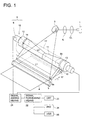
The following describes the general configuration of
the image reading system as the first embodiment with
reference to Fig. 1:
In the drawing, laser beam (stimulating lays) coming
out of the laser diode 1 passes through a collimator lens CL
and imaging lens IL and is scanned by a polygon mirror 3 to
perform (horizontal) scanning on a photo stimulable storage
phosphor sheet 4 at a specified beam diameter.
When beam applies to the photo stimulable storage
phosphor sheet 4 fed in the direction of arrow 1, there
occurs light emitted by the stimulable phosphor in conformity
to image information recorded on the photo stimulable storage
phosphor sheet 4. Part of this light emitted by the
stimulable phosphor (hereinafter referred to as "light") is
reflected by a reflection optical member 5 provided with
reflection enhancing coating as a reflection optical member,
and part of it directly enters the incoming end face 6a of
the light-collecting system 9 comprising a light-collecting
device 10 and a light guide plate 6 as a guide member to lead
light to the light-collecting device 10.
The light guide plate 6 is designed so that the width
of the cross section in the direction of leading light is
gradually smaller. Namely, it is designed to have a taper
structure such that the length in the horizontal scanning
direction (L2) in the ongoing end face 6b on the side of
light-collecting device 10 is smaller than length (L1) in the
direction of horizontal scanning in the incoming end face 6a
on the side of the photo stimulable storage phosphor sheet 4.
In this embodiment, the taper angle is designed so that
almost all reflections can be maintained. For example, when
the refractive index of light guide plate 6 is 1.5, no light
leaking from the light guide plate 6 so long as taper angle
is about 60. The length of light-collecting device 10 can be
reduced without reducing the reading width. Further, the
taper angle can be increased to reduce the light-collecting
efficiency to some extent. Further, the size of the longer
direction of the light-collecting device 10 can be more
reduced. This allows the light-collecting system 9 to be
designed in a small configuration.
Light reflected by the reflection optical member 5
enters the end face 6a on the side of the photo stimulable
storage phosphor sheet 4 of the light guide plate 6 made of
polymethyl methacrylate (PMMA) and other materials having a
high degree of transmittance as a guide member. Light having
entered the light guide plate 6 goes out of the ongoing end
face 6b on the side of the light-collecting device 10 as it
is reflected inside the light guide plate 6. Then it enters
the light-collecting device 10.
The light-collecting device 10 comprises (1) a longer
reflecting member 11 where the inner surface is a mirror
surface-like light reflecting surface and (2)
photomultipliers 12 and 13 as photo-detectors for
photoelectric conversion of the incoming light installed on
both ends of said reflecting member 11.
In the present embodiment, the filters 14 and 15 are
provided to attenuate the wavelength range of the laser beam
(stimulating lays) as as to contact the light receiving
surface of the photomultiplier 13.
In place of filters 14 and 15, filters can be installed
between the incoming surface of the light guide plate 6 and
photo stimulable storage phosphor sheet 4, or between the
light guide plate 6 and light-collecting device 10.
Signals subjected to photoelectric conversion by the
photomultipliers 12 and 13 are added by signal adding means
21, and are processed by signal processing means 22. Then
they are displayed on the CRT23, printed out by the printer
24 or recorded on an external recording system such as hard
disk.
High voltage supplied to the photomultipliers 12 and 13
is regulated so that signals subjected to photoelectric
conversion by the photomultipliers 12 and 13 will be on
almost the same level. Further, the signal adding means 21
can be based on either analog or digital principle.
An erasing lamp 15 is provided on the downstream side
of the light guide plate 6 to erase the image information
recorded on the photo stimulable storage phosphor sheet 4.
The image information remaining inside the photo stimulable
storage phosphor sheet 4 where After reading of image
information has been completed is erased by the erasing lamp
17.
The following describes the light-collecting device 10
using Fig. 2 representing the cross section vertical to the
longitudinal direction of the reflecting member in Figure 1,
wherein the reflecting surface is shown without the
peripheral portion, and Fig. 3 representing the cross section
in the longitudinal direction of the reflecting member in
Figure 1, wherein the reflecting surface is shown without the
peripheral portion.
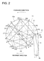
For simplicity, Fig. 2 shows the reflection of light on
the cross section vertical to longitudinal direction in a
cylindrical reflecting member without taper in the
longitudinal direction (shown by imaginary two-dot chain
liner in Fig. 1) 11'.
As shown in Fig. 2, the reflecting member 11 has a
light-incoming aperture 51 which is extended in the
longitudinal direction for entry of light and which is
connected with the ongoing end face 6b of the light guide
plate 6.
In the present embodiment, the perpendicular on the end
face 6b as the ongoing surface of the light guide plate 6 is
misaligned with the central direction of the cross section
(cross section vertical to the longitudinal direction), as
viewed from the longitudinal direction of the reflecting
member 11.
In the cross section vertical to longitudinal direction
of the reflecting member 11, the light reflecting surface 11a
inside the reflecting member 11 is designed in a structure
comprising a combination of arcs of two circle C1 and C2
having different curvature radiuses. Centers 01 and 02 of
each semicircle are misaligned.
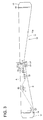
A shown in Fig. 3, taper with an angle of γ is provided
in the longitudinal direction of the reflecting member 11.
The area of the cross section of the reflecting member 11 is
smaller at the center side than at the end where
photomultipliers 12 and 13 are laid out.
Light having entered the reflecting member 11 is
attenuated in conformity to reflection rate on the reflecting
surface for each reflection in the light reflecting surface
11a. So the reflection rate of the light reflecting surface
11a is preferred to be higher.
The light reflecting surface 11a according to the
present embodiment is composes of a combination between
lustrous metal (deposited aluminum according to the present
embodiment) and multi-layer coating. The reflection rate is
95% or more.
The multi-layer coating according to the present
embodiment is designed in a 6-layered structure where TiO2
and NaF are overlapped alternately. However, the material is
not restricted to the above-mentioned material. To increase
reflection rate, it is preferred to be made up of materials
where the difference in refractive index is as big as
possible.
In addition, the light reflecting surface 11a can be
made of only multi-layer coating (20-0 or more layer) where
TiO2 and SiO2 are alternately overlapped, or a combination of
two types or more which are alternately overlapped. There
are many way of designing the multi-layer coating to ensure
the required spectral reflection rate.
The coating thickness of each layer is preferred to have the
wavelength equivalent to about one-fourth of light to be
reflected. Film formation is not restricted; namely, the
coating thickness on each layer need not be almost the same.
To minimize the absorption, it is necessary to select
the material of the multi-layer coating, which has a high
transmittance in the wavelength range of signal light.
The following describes how light proceeds in the reflecting
member 11:
<1> How light proceeds in the cross section vertical to
longitudinal direction in the reflecting member 11
The following description will be given with reference
to Fig. 2 according to the present embodiment and Fig. 4 as a
Reference Example of Fig. 2: Fig. 4 represents the reflecting
surface without peripheral surface.
Fig. 4 shows an example where the perpendicular on the
ongoing end face 6b as an ongoing surface of the light guide
plate 6 is directed toward the center of the cross section
(the cross section vertical to longitudinal direction) as
viewed from the longitudinal direction of the reflecting
member 11'. Further, the cross section is circular in the
longitudinal direction of the reflection member 11'.
In this configuration, the number of reflections is
very small (for example, one, two or three reflections).
There is light leaking from the light-incoming aperture 51'.
According to the present embodiment as shown in Fig, 2, by
contrast, the light entering the light-incoming aperture 51
of the reflecting member 11 rotates in one direction
(counterclockwise direction in Fig. 2. The rotational
direction of reflected light immediately after entry into the
light-collecting device is hereinafter referred to as
"forward direction"). Reflection is repeated during said
rotation.
When reflected light has passed between centers 01 and
02 of two semicircles, reflection is repeated in the
direction reverse to said one direction (clockwise direction
in Fig. 2. The direction reverse to said forward direction is
hereinafter referred to as "reverse direction"). Then light
goes out of the light-incoming aperture 51.
In Fig. 2, reflection of light was explained, for
simplicity, in the cross section vertical to longitudinal
direction when the taperless cylindrical reflecting member
11' in the longitudinal direction was used. The similar
action takes place on the tapered reflecting member 11. (Let
us assume here that N refers to the number of rotations from
the time when light enters the light-incoming aperture 51 to
the time when it goes out of the light-incoming aperture 51).
While the light having entered the light-collecting device 10
is rotating in the forward direction inside the reflecting
member 11, light does not leak from the light-incoming
aperture 51 [because the light-incoming aperture 51 faces
upward]. Despite rotation in the reverse direction, light
does not leak if it is out of the light-incoming aperture 51.
Hence, the amount of light leaking from the incoming opening
51 is reduced if light reaches the photomultiplier 12 during
reflection inside the reflection member 11.
<2> How light proceeds in the cross section vertical to
longitudinal direction in the reflecting member 11
The following description will be given with reference
to Fig. 3 according to the present embodiment and Fig. 5 as a
Reference Example: Fig. 5 represents the reflecting surface
without peripheral surface.
Fig. 5 shows a cylindrical reflecting member where the
cross section is almost constant. In this configuration, if
light enters approximately vertically with respect to light
reflected surface 11a', a considerable number of reflections
must take place until light reaches the light receiving
surface of the photomultipliers 12 and 13.
According to the present embodiment, by constant, the
light reflecting surface 11a of the reflecting member 11 is
tapered at an angle of γ in the longitudinal direction.
Hence, even if light enters vertically to the surface A,
reflection is carried out as follows:
= γ x n (n: number of reflections)
where the angle between the perpendicular of surface A and
light reflected on surface A is . Thus, light reaches the
photomultipliers 12 and 13 at a small number of reflections.
The above explanation was made with respect to the
light on the surface where the center of the reflecting
member 11 was vertically divided in the longitudinal
direction. Light entering the reflecting surface at a
different angle is also subjected to the same action by the
angle of taper at the point of reflection, although there is
a difference in degree.
Hence, taper is provided in the longitudinal direction
so that the cross section of the reflecting member 11 is
smaller at the central portion than at the end where
photomultipliers 12 and 13 are laid out. This ensures
incoming light reaches photomultipliers 12 and 13 at a
smaller number of reflection.
Light having entered the reflecting member 11 of the
light-collecting device 10 is attenuated for each reflection
according to the reflection rate of the light reflecting
surface 11a. So the reflection rate on the reflected surface
is preferred to be as high as possible. Further, the greater
the diameter of the light-collecting device, the smaller the
number of reflections. So when it is greater, light-collecting
efficiency is improved.
Thus, the area of the photoelectric surface of the
photomultiplier is preferred to be greater. The greater the
above-mentioned taper angle, the smaller the number of
reflections until light reaches the light receiving surface
of the photomultipliers 12 and 13.
If the inner diameter of the
light reflecting surface
11a is not sufficiently great with respect to the width of
the light-incoming aperture 51 (indicated by W in Fig. 2),
the amount of light leaking from the light-incoming
aperture
51 will be increased. The inner diameter of the
light
reflecting surface 11a, width of the light-incoming aperture
51 (W) and taper angle (γ) are determined so that the amount
of light reaching the photoelectric surface of the
photomultipliers 12 and 13 will be the maximum.
The above configuration provides the following effects:
In this case, the end face 6b from which light of the
light guide plate 6 comes out is preferred to be configured
so that there is no clearance between it and the light-incoming
aperture 51 of the reflecting member 11.
The present invention is not restricted to above
embodiments. It also allows the following variations:
Such a configuration reduces the area of the light-incoming
aperture 51 inside the reflecting member 11. This
reduces the amount of light leaking from the light-incoming
aperture 51. Thus, the light containing image information can
be sent to the photo-detector with high efficiency. Hence,
the image information with excellent SN ratio can be obtained
or image information reading time can be reduced.
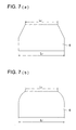
In Fig. 9, taper angle (δ) is provided over the entire
range in the direction of thickness of the cross section in
the direction where light is led, and is made gradually
smaller as light comes closer to the light-incoming aperture
51. As shown in Fig. 10 (a), taper can be provided only
partially.
A curved taper can also be provided as shown in Fig. 10
(b).
(2) Second Embodiment
The following describes the Second Embodiment with
reference to Fig. 11 as a configuration diagram to describe
the second embodiment and Fig. 12 representing the cross
section viewed from the direction A in Fig. 11, as a drawing
to show the reflecting surface without peripheral portion.
The present embodiment also relates to the system to read
image information recorded on the photo stimulable storage
phosphor sheet.
In these figures, the laser beam starting from a laser
diode (not illustrated) is scanned by a polygon mirror (not
illustrated), and is subjected to horizontal scanning on the
photo stimulable storage phosphor sheet 204.
Then light emitted by the stimulable phosphor in
conformity to image information recorded on the photo
stimulable storage phosphor sheet 204 is produced from both
sides (surface and back) of the photo stimulable storage
phosphor sheet 204. Light emitted by the stimulable phosphor
(hereinafter referred to as "light") on the back side which
is the opposite of the side where laser beam was present
enters the light-collecting system 209.
The light-collecting system 209 consists of a light-collecting
device 210 and a light guide plate 206 as a guide
member to lead light to the light-collecting device 210. The
light-collecting device 210 consists of (1) a longer
reflecting member 211 where the inner surface is a mirror
surface-like light reflecting surface, and (2)
photomultipliers 12 and 13 as photo-detectors to detect the
incoming light installed on both ends of said reflecting
member 211.
As shown in Fig. 12, the cross section vertical to
longitudinal direction of the reflecting member 211 in the
present embodiment is designed so that one circle is formed
by the cross section of the light reflecting surface 211a.
The light reflecting surface 211a has the similar reflection
characteristics as that of the light reflecting surface 11a
in the first embodiment.
The light having entered from the light-incoming
aperture 251 of the reflecting member 211 is reflected by the
light reflecting surface 211a in the forward direction. The
light having contacted the light reflecting surface 211
changes the direction of reflection to the reverse direction
and comes out of the light-incoming aperture 251 externally.
Thus, for the cross section of the reflecting member
211 in the present embodiment, light does not leak from the
light-incoming aperture 251 unless reflection occurs multiple
numbers of times. This is the same as in the case of the
cross section of reflecting member 11 according to the first
embodiment where two semicircles with different radiuses are
put together.
The above-mentioned configuration provides the same
effect as the first embodiment. It should be noted that the
light-collecting system 209 is used to collect light on the
back side of the photo stimulable storage phosphor sheet 204
in the above-mentioned configuration. As shown in Fig. 3, it
is also possible to install additional light-collecting
systems 209' and 209'' having the same configuration as the
light-collecting system 209, and to collect light emitted on
the back and surface of the photo stimulable storage
phosphor sheet 204, using a total of three light-collecting
systems 209, 209' and 209"". Fig. 13 shows the reflecting
surface without the peripheral surface of the light-collecting
device.
It is also possible to collect light emitted on the
back and surface of the photo stimulable storage phosphor
sheet 204, using two light-collecting systems, namely, a
light-collecting system 209 and either light-collecting
system 209' or 209''. It is also possible to collect light
emitted on the back of the photo stimulable storage phosphor
sheet 204 using only light-collecting systems 209' and 209'',
without the light-collecting system 209.
Said embodiment was explained with reference to the
example of using the photo stimulable storage phosphor sheet.
It goes without saying that the explanation also applies to
the reading system to read the document transmissive to light
such as film.
(3) Third Embodiment
The following describes the third embodiment with
reference to Fig. 14 as a main component configuration
diagram illustrating a third embodiment: The reflecting
member in Fig. 14 shows only the reflecting surface without
peripheral portion.
In the first and second embodiments, Taper is provided
in the longitudinal direction to ensure that the area of the
cross section of the reflecting member 11 is smaller at the
center side than at the end where photomultipliers 12 and 13
are laid out. In the present embodiment, the reflecting
member 311 of the light-collecting device 310 has a
photomultiplier 312 installed on one end. Taper is provided
to ensure that the area of the cross section vertical to
longitudinal direction of the reflecting member 311 is
gradually reduced at the end where the photomultiplier 312 is
not placed than at the end where it is placed.
A reflection mirror 331 provided with reflection
enhancing coating is installed as an end reflecting member at
the end where the photomultiplier 312 is not placed.
According to this configuration,
part of light entering the reflecting member 311 of the
light-collecting device 310 directly enters the light
receiving surface of the photomultiplier 312, and part of it
is reflected by the light reflecting surface 311a of the
reflecting member 311 to enter the light receiving surface of
the photomultiplier 312. After multiple reflections inside
the reflecting member 311, part of light entering in the
direction opposite to the photomultiplier 312 to changes
direction to go to the photomultiplier 312. The part of
remaining light is reflected by the reflection mirror 331 to
enter the photoelectric surface of the photomultiplier 312
after multiple reflections inside the reflecting member 311.
The above-mentioned configuration provides the same
effect as the first embodiment. Leakage of light from the
reflecting member end 311 of the light-collecting device 310
is eliminated by installation of a reflection mirror 331 on
the side where the photomultiplier 312 is not installed.
Thus, the light containing image information can be sent to
the photo-detector with high efficiency. Hence, the image
information with excellent SN ratio can be obtained or image
information reading time can be reduced.
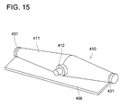
(4) Fourth Embodiment
The following describes the fourth embodiment with
reference to Fig. 15 as a main component configuration
diagram illustrating a fourth embodiment:
The reflecting member 11 of the first and second
embodiments is tapered in the longitudinal direction so that
the cross section of the reflecting member 11 is smaller at
the central portion than at the end where photomultipliers 12
and 13 are laid out. In the reflecting member 411 of the
light-collecting device 410, photomultiplier 412 is provided
at the center on the side of the reflecting member 411, and
taper is provided so that the area of the cross section
vertical to the longitudinal direction of the reflection
member 411 is greater at the center side than at the end.
An reflecting mirror 431 provided with reflection
enhancing coating is installed as an end reflecting member on
both sides of the reflecting member 411. According to the
above-mentioned configuration, photomultiplier 412 is
provided at the center on the side of the reflecting member
411, and the area of the cross section vertical to the
longitudinal direction of the reflection member 411 is
greater at the center side than at the end. This reduces the
number of reflections inside the reflecting member 411
leading to the photomultiplier 412, and decreases attenuation
by reflection.
The reduced number of reflections inside the reflecting
member 411 decreases the amount of light leaking from the
light-incoming aperture of the reflecting member 411
connected with a light guide plate 406, with the result that
light-collecting efficiency is improved.
Thus, the light containing image information can be
sent to the photomultiplier 412 with high efficiency. Hence,
the image information with excellent SN ratio can be obtained
and image information reading time can be reduced.
The photomultiplier 412 is provided at the center on
the side of the reflecting member 411. This makes it possible
to use a small-sized low-cost photo-detector, instead of a
costly, longer or larger-diameter photo-detector. Further,
the photomultiplier is not positioned at the end in the
longitudinal direction of the light-collecting device. This
allows the length in the longitudinal direction to be
decreased. The above explanation is based on one
photomultiplier installed at the center. Two or more can be
installed. The installation position is not restricted to the
center in the longitudinal direction of the light-collecting
device.
Part of the light entering the reflecting member of the
light-collecting device in the first to third embodiments
directly enters the photomultiplier. Part of it is reflected
by the reflection mirror to go to the photomultiplier. A
substantial reduction in the number of reflections inside the
light-collecting device can be provided, as compared with the
cylindrical light-collecting device shown in Fig. 5. If the
number of internal reflections is assumed as M, the
relationship with the number of reflections, N, discussed in
the first embodiment is M < N, there is almost no light
leaking from the light-collecting device aperture. This fact
is what the present inventors have found out.
In practice, the present inventors manufactured a
light-collecting device characterized by excellent light-collecting
efficiency when the cross section structure and
taper structure meeting these requirements were provided.
Figure 16 gives the result of measuring the light-collecting
efficiency in the longitudinal direction of
various types of light-collecting devices when the light
reflecting surface is 98%.
The light-collecting device of each plot is as follows:
Symbol (•): The cylindrical (with mirror) light-collecting
device has a cylindrical form not tapered as shown in Fig. 5.
In this light-collecting device as shown in Fig. 4, the shape
of the cross section is such that the perpendicular on the
end face as an ongoing surface of the guide plate is the
reflecting member facing toward the center of the cross
section (cross section vertical to the longitudinal
direction) viewed from the longitudinal direction of the
reflecting member. A photomultiplier is located on one end
face and a reflection mirror is installed on the other end
face.
Symbol (Δ): The tapered (with mirror) light-collecting device
is tapered in such a way that the area of the cross section
of the surface vertical to the longitudinal direction of the
reflecting member is gradually reduced as light goes from one
end to the other end, as shown in Fig. 14. The shape of the
cross section is shown in Fig. 4; namely, the perpendicular
on the end face as the ongoing surface of the light guide
plate refers to the cross section (the cross section vertical
to longitudinal direction) viewed from the longitudinal
direction of the reflecting member. A photomultiplier is
installed on the side of the end face with wider area, while
a reflection mirror is mounted on the side of the end face
with less wider area. This light-collecting device has such a
structure.
Symbol (▿) : The V-type light-collecting device is tapered in
such a way that the area of the cross section of the surface
vertical to the longitudinal direction of the reflecting
member as shown in Fig. 3 is gradually reduced as light goes
from the central side to the end. As shown in Fig. 4, the
shape of the cross section is the reflecting member wherein
the perpendicular on the end face the ongoing surface of the
light guide plate faces toward the center of the cross
section (the cross section vertical to longitudinal
direction) viewed from the longitudinal direction of the
reflecting member, and the photomultiplier is provided on the
side of both end faces in this light-collecting device.
Symbol (): The taper type of the taper type + ammonite
light-collecting device refers to the type shown in Fig. 14
which is tapered in such a way that the area of the cross
section of the surface vertical the longitudinal direction of
the reflecting member is gradually reduced as light goes to
one end to the other end. The ammonite refers to the type of
the light-collecting device where the shape of the cross
section is shown in Fig. 2 which. Namely, the perpendicular
on the end face as the ongoing surface of the light guide
member is misaligned with the central direction of the cross
section (the cross section vertical to longitudinal
direction) viewed from the longitudinal direction of the
reflecting member. In the cross section vertical to the
longitudinal direction of the reflecting member, the light
reflecting surface as an inner surface of the reflecting
member consists of a combination of two arcs of two circles
having different curvature radiuses, wherein the center of
each semicircle is misaligned in this reflecting member. A
photomultiplier is installed on the end face with wider area
and a reflection mirror is mounted on the end face with less
wide area in this light-collecting device.
Symbol (◆): "V type" in "V type + ammonite light-collecting
device" means that taper is provided so that the area of the
cross section vertical to longitudinal direction of the
reflecting member shown in Fig. 3 is smaller at the center
side than at the end. The ammonite refers to the type of the
light-collecting device where the shape of the cross section
is shown in Fig. 2 which. Namely, the perpendicular on the
end face as the ongoing surface of the light guide member is
misaligned with the central direction of the cross section
(the cross section vertical to longitudinal direction) viewed
from the longitudinal direction of the reflecting member. In
the cross section vertical to the longitudinal direction of
the reflecting member, the light reflecting surface as an
inner surface of the reflecting member consists of a
combination of two arcs of two circles having different
curvature radiuses, wherein the center of each semicircle is
misaligned in this reflecting member. A photomultiplier is
installed on both end faces in this light-collecting device.
As can be seen from the Figure, light-collecting
efficiency is 70% or more for the V type light-collecting
device of plot ▿, and is 85% or more for the V type +
ammonite light-collecting device of plot ◆.
When consideration is given to the fact that the
sensitivity of photoelectric surface of the shorter
photomultiplier used in the present invention is about 1.5
times that of the photoelectric surface of the longer
photomultiplier, replacement is sufficiently possible in
terms of SN as well.
Further, this measurement data represents the light-collecting
efficiency when the reflection rate of light
reflecting surface of the reflecting member of the light-collecting
device is 98%. Light-collecting efficiency can be
further increased by improving the reflecting surface
performances
From the above description, it can be confirmed that
use of the light-collecting device according to the present
invention eliminates the need of using a large sized light-collecting
guide or a very expensive longer photomultiplier
which have been used so far. It provides a great advantage
of making it possible to create a small sized low cost image
reading system and to ensure improved SN.
As described above, the present invention provides the
following effects:
Thus, light does not leak from the light-incoming aperture
while the light entering the light-collecting device rotates
in one direction.
Even if said light rotates in the direction reverse to
one direction, light does not leak if light fails to enter
the light-incoming aperture.This reduces the amount of light leaking from the
light-incoming aperture before light reaches the photo-detector.
The light containing image information can be sent
to the photo-detector with high efficiency. Thus, the image
information with excellent SN ratio can be obtained and image
information reading time can be reduced. If the reflecting member is sufficiently long in the
longitudinal direction, reflection is repeated so that much
light rotates in one direction. After that, reflection is
repeated so that light rotates in the direction reverse to
said direction. As the reflecting member is reduced in the
longitudinal direction, there is a decrease in the amount of
light which repeats reflection by rotating in the direction
reverse to one direction, and an increase in the amount of
light which repeats reflection by rotating in one direction.
Namely, there is an increase in the amount of light reaching
the end of the reflecting member in the longitudinal
direction before repeating reflection by rotation in the
direction reverse to one direction. (3) According to the present invention, the perpendicular of
said light-incoming aperture is misaligned with the center
direction of the cross section of the surface vertical to the
longitudinal direction of said light-collecting device. This
increases the number of reflections until the light coming
from said light-incoming aperture leaks from the light-incoming
aperture.
This also reduces the amount of light leaking from the
light-incoming aperture before light reaches the photo-detector.
The light containing image information can be sent
to the photo-detector with high efficiency. Thus, the image
information with excellent SN ratio can be obtained and image
information reading time can be reduced. (4) According to the present invention, said reflecting
member has a circular arc light reflecting surface having at
least two curvature radiuses. This allows reflection to be
repeated so that much light rotates in one direction; then
reflection is repeated so that light rotates in the direction
reverse to said direction.
Thus, there is a decrease in the amount of light
leaking from the light-incoming aperture before reaching the
photo-detector. The light containing image information can be
led to the photo-detector with high efficiency, thereby
ensuring image information with excellent SN ratio, or
reducing image information reading time. (5) According to the present invention, said reflecting
member has a light reflecting surface comprising multiple
plane surfaces inscribing or circumscribing a circular arc
light reflecting surface having at least two curvature
radiuses. This allows reflection to be repeated so that light
rotates in one direction; then reflection is repeated so that
light rotates in the direction reverse to said direction.
Thus, there is a decrease in the amount of light
leaking from the light-incoming aperture before reaching the
photo-detector. The light containing image information can be
led to the photo-detector with high efficiency, thereby
ensuring image information with excellent SN ratio, or
reducing image information reading time. (6) According to the present invention, on the cross section
vertical to the longitudinal direction of said reflecting
member, said reflecting member has a circular arc light
reflecting surface having at least two curvature radiuses, or
a light reflecting surface comprising multiple plane surfaces
inscribing or circumscribing a circular arc having at least
two curvature radiuses. This allows reflection to be repeated
so that light rotates in one direction; then reflection is
repeated so that light rotates in the direction reverse to
said direction. Thus, there is a decrease in the amount of
light leaking from the light-incoming aperture before
reaching the photo-detector. The light containing image
information can be led to the photo-detector with high
efficiency, thereby ensuring image information with excellent
SN ratio, or reducing image information reading time. (7) According to the present invention, said photo-detector
is installed on each end of said reflecting member, and the
cross section of the surface vertical to the longitudinal
direction of said reflecting member is smaller at the central
portion than at the end. In other words, the diameter
increases from the center of the reflecting member toward
both ends. This configuration reduces the number of
reflections within the reflecting member until the photo-detector
is reached, and decreases attenuation due to
reflection.
Further, the decreased number of reflections reduces
the amount of light leaking from the light-incoming aperture,
and increases light-collecting efficiency. Thus, the light
containing image information can be sent to the photo-detector
with high efficiency. Hence, the image information
with excellent SN ratio can be obtained or image information
reading time can be reduced.Further, a photo-detector is installed on each end of
the long reflecting member. This allows use of a small-sized
low-cost photo-detector, instead of a costly, longer or
larger-diameter photo-detector.In addition, installation of a photo-detector on each
end of the reflecting member reduces the length of a light
path from the incoming position to the photo-detector. Thus,
the light containing image information can be led to the
photo-detector with high efficiency, thereby ensuring image
information with excellent SN ratio, or reducing image
information reading time. (8) According to the present invention, said reflecting
member has either lustrous metal or multi-layer coating.
This ensures a high reflection rate and reduces light
attenuation.
Thus, the light containing image information can be led
to the photo-detector with high efficiency, thereby ensuring
image information with excellent SN ratio, or reducing image
information reading time. (9) According to the present invention, said reflecting
member having a wavelength selectivity reduces the reflection
rate of light which becomes noise other than frequency of
light including image information.
Further, it also eliminates the need of a filter having
wavelength selectivity or permits the performances thereof to
be reduced. Thus, the SN ratio of the light containing image
information received by the detector can be improved, thereby
ensuring image information with excellent SN ratio, or
reducing image information reading time. (10) According to the present invention, the cross section of
the surface vertical to the longitudinal direction of said
reflecting member is smaller as light goes from the end
equipped with said photo-detector to the end without it. In
other words, the area of the cross section is reduced as
light goes from the end of the reflecting member provided
with said photo-detector toward the end without it. This
configuration reduces the number of reflections within the
reflecting member until the photo-detector is reached, and
decreases attenuation due to reflection.
Further, the decreased number of reflections reduces
the amount of light leaking from the light-incoming aperture,
and increases light-collecting efficiency. Thus, the light
containing image information can be sent to the photo-detector
with high efficiency. Hence, the image information
with excellent SN ratio can be obtained or image information
reading time can be reduced.Further, the photo-detector installed on the end of the
reflecting member allows use of a small-sized low-cost photo-detector,
instead of a costly, longer or larger-diameter
photo-detector.In addition, installation of the photo-detector on one
end of the reflecting member reduces costs. (11) According to the present invention, said photo-detector
is installed at the center on the side of said reflecting
member, and the cross section of the surface vertical to the
longitudinal direction of said reflecting member is greater
at the central portion than at the end. This configuration
reduces the number of reflections within the reflecting
member until the photo-detector is reached, and decreases
attenuation due to reflection.
Further, the decreased number of reflections reduces
the amount of light leaking from the light-incoming aperture,
and increases light-collecting efficiency.
Thus, the light containing image information can be sent to
the photo-detector with high efficiency. Hence, the image
information with excellent SN ratio can be obtained or image
information reading time can be reduced.Further, the photo-detector installed at the center on
the side of said reflecting member allows use of a small-sized
low-cost photo-detector, instead of a costly, longer or
larger-diameter photo-detector. (12) According to the present invention, an end reflecting
member is installed on one of two ends of said reflecting
member where the photo-detector is not installed. This
eliminates the amount of light leaking from the end of the
light-collecting device. Thus, the light containing image
information can be sent to the photo-detector with high
efficiency. Hence, the image information with excellent SN
ratio can be obtained or image information reading time can
be reduced. (13) According to the present invention, said end reflecting
member having either lustrous metal or multi-layer coating
ensures increased reflection rate and decreased light
attenuation.
Thus, the light containing image information can be
sent to the photo-detector with high efficiency. Hence, the
image information with excellent SN ratio can be obtained or
image information reading time can be reduced. (14) According to the present invention, said reflecting
member having a wavelength selectivity reduces the reflection
rate of light which becomes noise other than frequency of
light including image information.
Further, it also eliminates the need of a filter having
wavelength selectivity or permits the performances thereof to
be reduced.Thus, the SN ratio of the light containing image
information received by the detector can be improved, thereby
ensuring image information with excellent SN ratio, or
reducing image information reading time. (15) According to the present invention, an optical filter
having wavelength selectivity is installed either on the
light receiving surface of said photo-detector or in the
vicinity of said light-incoming aperture. This reduces the
light which becomes noise other than frequency of light
including image information.
Thus, the SN ratio of the light containing image
information received by the detector can be improved, thereby
ensuring image information with excellent SN ratio, or
reducing image information reading time. (16) According to the present invention, a light guide member
installed to lead light to the light-incoming aperture of
said light-collecting device increases the degree of freedom
in the layout of the system, and allows flexible system
configuration. (17) According to the present invention, said light-collecting
device being the one according to any one of
Claims 1 to 15 allows use of a small-sized low-cost photo-detector,
instead of a costly, longer or larger-diameter
photo-detector.
Further, the light containing image information can be
sent to the photo-detector with high efficiency. Hence, the
image information with excellent SN ratio can be obtained or
image information reading time can be reduced. (18) According to the present invention, the perpendicular of
the ongoing surface of said light guide member is misaligned
with the center of the cross section of the surface vertical
to the longitudinal direction of said light-collecting
device. This increases the number of reflections until the
light coming from light-incoming aperture of the reflecting
member of the light-collecting device leaks from the light-incoming
aperture.
Thus, there is a decrease in the amount of light
leaking from the light-incoming aperture before reaching the
photo-detector. The light containing image information can be
led to the photo-detector with high efficiency, thereby
ensuring image information with excellent SN ratio, or
reducing image information reading time. (19) According to the present invention, aid light guide
member is designed to ensure that the width in the
longitudinal direction is smaller at the ongoing aperture
than at the light-incoming aperture. This makes it possible
to decrease the width of the longitudinal direction
(horizontal scanning direction) of the light-incoming
aperture of the light-collecting device. In other words, it
is possible to reduce the length of the longitudinal
direction of the light-collecting device and to reduce the
system size, without deteriorating the picture quality. (20) According to the present invention, said light guide
member is designed so that only the thickness in the
direction vertical to the longitudinal direction is smaller
at the ongoing aperture than at the light-incoming aperture.
This makes it possible to reduce the area of the light-incoming
aperture in the reflecting member.
Thus, there is a decrease in the amount of light
leaking from the light-incoming aperture, and the light
containing image information can be led to the photo-detector
with high efficiency, thereby ensuring image information with
excellent SN ratio, or reducing image information reading
time. (21) According to the present invention, reflection
preventive coating is provided on either the incoming surface
or ongoing surface of said light guide member. This makes it
possible to reduce the light reflection in either the
incoming surface or ongoing surface of the light guide.
Thus, the light containing image information can be led to
the photo-detector with high efficiency.
This ensures image information with excellent SN ratio,
or reduces image information reading time. (22) According to the present invention, said light-collecting
device is a light-collecting device according to
any one of Claims 1 to 15. This allows use of a small-sized
low-cost photo-detector, instead of a costly, longer or
larger-diameter photo-detector.
The light containing image information can be led to
the photo-detector with high efficiency, thereby ensuring
image information with excellent SN ratio, or reducing image
information reading t (23) According to the present invention, when the light-collecting
system according to any one of Claims 16 to 21 is
provided, it is possible to increases the degree of freedom
in the layout of the light-collecting device and allows
flexible system configuration.
It is also possible to use a small-sized low-cost
photo-detector, instead of a costly, longer or larger-diameter
photo-detector.Further, the light containing image information can be
sent to the photo-detector with high efficiency. Hence, the
image information with excellent SN ratio can be obtained or
image information reading time can be reduced. (24) According to the present invention, said light-collecting
device is the one according to any one of Claims 1
to 15. This allows use of a small-sized low-cost photo-detector,
instead of a costly, longer or larger-diameter
photo-detector.
Further, the light containing image information can be
sent to the photo-detector with high efficiency. Hence, the
image information with excellent SN ratio can be obtained or
image information reading time can be reduced. (25) According to the present invention, when the light-collecting
system according to any one of Claims 16 to 21 is
provided, it is possible to increases the degree of freedom
in the layout of the light-collecting device and allows
flexible system configuration.
It is also possible to use a small-sized low-cost
photo-detector, instead of a costly, longer or larger-diameter
photo-detector.
Further, the light containing image information can be
sent to the photo-detector with high efficiency. Hence, the
image information with excellent SN ratio can be obtained or
image information reading time can be reduced.
Disclosed embodiment can be varied by a skilled person
without departing from the spirit and scope of the invention.