EP1143173A2 - Torque modulation shift control system and method - Google Patents
Torque modulation shift control system and method Download PDFInfo
- Publication number
- EP1143173A2 EP1143173A2 EP01108108A EP01108108A EP1143173A2 EP 1143173 A2 EP1143173 A2 EP 1143173A2 EP 01108108 A EP01108108 A EP 01108108A EP 01108108 A EP01108108 A EP 01108108A EP 1143173 A2 EP1143173 A2 EP 1143173A2
- Authority
- EP
- European Patent Office
- Prior art keywords
- torque
- recited
- disengagement
- ramp
- gear
- Prior art date
- Legal status (The legal status is an assumption and is not a legal conclusion. Google has not performed a legal analysis and makes no representation as to the accuracy of the status listed.)
- Granted
Links
Images


Classifications
-
- B—PERFORMING OPERATIONS; TRANSPORTING
- B60—VEHICLES IN GENERAL
- B60W—CONJOINT CONTROL OF VEHICLE SUB-UNITS OF DIFFERENT TYPE OR DIFFERENT FUNCTION; CONTROL SYSTEMS SPECIALLY ADAPTED FOR HYBRID VEHICLES; ROAD VEHICLE DRIVE CONTROL SYSTEMS FOR PURPOSES NOT RELATED TO THE CONTROL OF A PARTICULAR SUB-UNIT
- B60W10/00—Conjoint control of vehicle sub-units of different type or different function
- B60W10/04—Conjoint control of vehicle sub-units of different type or different function including control of propulsion units
- B60W10/06—Conjoint control of vehicle sub-units of different type or different function including control of propulsion units including control of combustion engines
-
- B—PERFORMING OPERATIONS; TRANSPORTING
- B60—VEHICLES IN GENERAL
- B60W—CONJOINT CONTROL OF VEHICLE SUB-UNITS OF DIFFERENT TYPE OR DIFFERENT FUNCTION; CONTROL SYSTEMS SPECIALLY ADAPTED FOR HYBRID VEHICLES; ROAD VEHICLE DRIVE CONTROL SYSTEMS FOR PURPOSES NOT RELATED TO THE CONTROL OF A PARTICULAR SUB-UNIT
- B60W10/00—Conjoint control of vehicle sub-units of different type or different function
- B60W10/10—Conjoint control of vehicle sub-units of different type or different function including control of change-speed gearings
- B60W10/11—Stepped gearings
- B60W10/111—Stepped gearings with separate change-speed gear trains arranged in series
-
- B—PERFORMING OPERATIONS; TRANSPORTING
- B60—VEHICLES IN GENERAL
- B60W—CONJOINT CONTROL OF VEHICLE SUB-UNITS OF DIFFERENT TYPE OR DIFFERENT FUNCTION; CONTROL SYSTEMS SPECIALLY ADAPTED FOR HYBRID VEHICLES; ROAD VEHICLE DRIVE CONTROL SYSTEMS FOR PURPOSES NOT RELATED TO THE CONTROL OF A PARTICULAR SUB-UNIT
- B60W30/00—Purposes of road vehicle drive control systems not related to the control of a particular sub-unit, e.g. of systems using conjoint control of vehicle sub-units
- B60W30/18—Propelling the vehicle
- B60W30/19—Improvement of gear change, e.g. by synchronisation or smoothing gear shift
-
- F—MECHANICAL ENGINEERING; LIGHTING; HEATING; WEAPONS; BLASTING
- F16—ENGINEERING ELEMENTS AND UNITS; GENERAL MEASURES FOR PRODUCING AND MAINTAINING EFFECTIVE FUNCTIONING OF MACHINES OR INSTALLATIONS; THERMAL INSULATION IN GENERAL
- F16H—GEARING
- F16H63/00—Control outputs from the control unit to change-speed- or reversing-gearings for conveying rotary motion or to other devices than the final output mechanism
- F16H63/40—Control outputs from the control unit to change-speed- or reversing-gearings for conveying rotary motion or to other devices than the final output mechanism comprising signals other than signals for actuating the final output mechanisms
- F16H63/50—Signals to an engine or motor
- F16H63/502—Signals to an engine or motor for smoothing gear shifts
-
- F—MECHANICAL ENGINEERING; LIGHTING; HEATING; WEAPONS; BLASTING
- F16—ENGINEERING ELEMENTS AND UNITS; GENERAL MEASURES FOR PRODUCING AND MAINTAINING EFFECTIVE FUNCTIONING OF MACHINES OR INSTALLATIONS; THERMAL INSULATION IN GENERAL
- F16H—GEARING
- F16H2306/00—Shifting
- F16H2306/32—Preparing the opening or release of the torque transmitting element
-
- F—MECHANICAL ENGINEERING; LIGHTING; HEATING; WEAPONS; BLASTING
- F16—ENGINEERING ELEMENTS AND UNITS; GENERAL MEASURES FOR PRODUCING AND MAINTAINING EFFECTIVE FUNCTIONING OF MACHINES OR INSTALLATIONS; THERMAL INSULATION IN GENERAL
- F16H—GEARING
- F16H2306/00—Shifting
- F16H2306/40—Shifting activities
- F16H2306/44—Removing torque from current gears
-
- F—MECHANICAL ENGINEERING; LIGHTING; HEATING; WEAPONS; BLASTING
- F16—ENGINEERING ELEMENTS AND UNITS; GENERAL MEASURES FOR PRODUCING AND MAINTAINING EFFECTIVE FUNCTIONING OF MACHINES OR INSTALLATIONS; THERMAL INSULATION IN GENERAL
- F16H—GEARING
- F16H2306/00—Shifting
- F16H2306/40—Shifting activities
- F16H2306/46—Uncoupling of current gear
-
- F—MECHANICAL ENGINEERING; LIGHTING; HEATING; WEAPONS; BLASTING
- F16—ENGINEERING ELEMENTS AND UNITS; GENERAL MEASURES FOR PRODUCING AND MAINTAINING EFFECTIVE FUNCTIONING OF MACHINES OR INSTALLATIONS; THERMAL INSULATION IN GENERAL
- F16H—GEARING
- F16H61/00—Control functions within control units of change-speed- or reversing-gearings for conveying rotary motion ; Control of exclusively fluid gearing, friction gearing, gearings with endless flexible members or other particular types of gearing
- F16H61/02—Control functions within control units of change-speed- or reversing-gearings for conveying rotary motion ; Control of exclusively fluid gearing, friction gearing, gearings with endless flexible members or other particular types of gearing characterised by the signals used
- F16H61/0202—Control functions within control units of change-speed- or reversing-gearings for conveying rotary motion ; Control of exclusively fluid gearing, friction gearing, gearings with endless flexible members or other particular types of gearing characterised by the signals used the signals being electric
- F16H61/0248—Control units where shifting is directly initiated by the driver, e.g. semi-automatic transmissions
-
- F—MECHANICAL ENGINEERING; LIGHTING; HEATING; WEAPONS; BLASTING
- F16—ENGINEERING ELEMENTS AND UNITS; GENERAL MEASURES FOR PRODUCING AND MAINTAINING EFFECTIVE FUNCTIONING OF MACHINES OR INSTALLATIONS; THERMAL INSULATION IN GENERAL
- F16H—GEARING
- F16H61/00—Control functions within control units of change-speed- or reversing-gearings for conveying rotary motion ; Control of exclusively fluid gearing, friction gearing, gearings with endless flexible members or other particular types of gearing
- F16H61/70—Control functions within control units of change-speed- or reversing-gearings for conveying rotary motion ; Control of exclusively fluid gearing, friction gearing, gearings with endless flexible members or other particular types of gearing specially adapted for change-speed gearing in group arrangement, i.e. with separate change-speed gear trains arranged in series, e.g. range or overdrive-type gearing arrangements
Definitions
- the present invention relates generally to a shift control system for vehicular drive lines and more particularly to a semi-automatic shift control system suitable for heavy duty trucks that utilizes torque modulation to improve gear disengagement and shift control.
- the present invention also includes a method for improving gear disengagement and shift control.
- Vehicle transmissions are well known in the art. Heavy duty vehicles typically include a manual or a semi-automatic transmission. The basic principal behind such semi-automatic transmissions is to assist a driver in performing a manually selected gear ratio change using a system that is at least partially automated. While such transmissions are becoming more prevalent, those skilled in the art continue to attempt to improve or enhance current designs.
- the driver manually operates a clutch and a gear shift lever.
- the master clutch disengages the output shaft of the engine from the input shaft of the transmission so that the transmission is moved out of engagement with a pre-selected gear and into a neutral position.
- the master clutch is then released to allow the internal rotating members of the transmission to maintain their rotational speed and approximates a desired engine speed via the engine throttle that corresponds to an appropriate synchronized speed for engaging the new gear.
- the driver operates the master clutch and moves the shift lever. This requires both skill and experience.
- Semi-automatic shift control enables automatic shifting between higher sequentially related forward gear ratios.
- a controller causes the engine fuel supply to be increased and decreased, possibly repeatedly, while actuators urge the existing engaged jaw clutch assembly toward disengagement to create a torque break sufficient for disengagement.
- engine acceleration and deceleration rates with some engines are significantly fast enough to cause jaw clutches to sometimes remain locked during electronically controlled torque reversals that facilitate disengagement.
- Some known fuel control systems "blip" torque positive and “negative” in percentage increments and then hold the same for a given duration of time, in the manner similar to a step function, and then may increase as necessary to achieve disengagement.
- Negative torque may be induced by commanding zero fuel to the engine, allowing natural engine friction to provide the "negative" torque reversal to the system.
- a challenge that designers of semi-automatic transmission systems face is to improve or simplify the task of shifting gears and to do so in an efficient and effective manner that appears seamless to the driver.
- This invention provides an effective system and method for improving gear disengagement and shifting.
- the present invention recognizes the aforementioned challenges and the limitations associated with conventional systems and methods and provides a torque modulation shift control system and method that improves gear disengagement in a cost-effective and efficient manner that appears seamless to the driver.
- the present invention provides the additional advantage of being achievable with software modification. Hence, the system and method is quite economical when compared with conventional systems and methods.
- a shift control system is provided that is suitable for semi-automatic transmissions in heavy duty vehicles.
- the torque modulation system includes logic circuitry that may employ a torque function or algorithm to control the rate of change of torque, both positive and negative, and may provide for longer dwell time in the torque clutch disengagement range.
- the dithering torque that is commanded by the system can, by way of example and without limitation, reduce momentary peak torque values from ⁇ 14% to ⁇ 10%, or less, using J1939 torque values over a datalink.
- the purpose of such dithering torque is to help ensure that "zero torque" will be achieved in a relatively brief span of time even if the engine torque information is over or underreported to the system.
- dwell time at maximum or minimum peak torque which provides little or no functional benefit to disengagement and shifting, is not required.
- a method for improving gear disengagement and shift control in accordance with the principles of the invention is also disclosed.
- FIG. 1 shows a block diagram of a semi-automatic compound transmission.
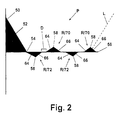
- FIG. 2 is graphic illustration of an implementation of a method of this invention.
- FIG. 3 is graphic illustration of a conventional method of dithering torque values to facilitate disengagement.
- FIG. 1 schematically and diagrammatically illustrates a type of compound mechanical vehicle transmission system commonly used with heavy duty trucks.
- a main section 4 is coupled in series to an auxiliary section 6 controlled by a shift control system 15.
- the shift control system 15 includes a means for sensing and providing a suitable signal 33 to an actuator means 34 that is operative to enable automatic shifting at the particular gear position desired.
- the system 15 further includes a means operative to enable automatic shifting, preferably an electronic controller 16, a fuel control means 26 and a shift actuator 34.
- Main section 4 is operatively coupled to the drive shaft of the vehicle engine 5 by master friction clutch 8.
- the engine 5 provides a motive force to propel the vehicle via the transmission 2.
- Output shaft 10 of auxiliary section 6 is operatively coupled - typically by means of a drive shaft and drive axle - to the drive wheels of the vehicle (not shown).
- a multiple speed drive axle can be substituted for, or used in connection with, auxiliary section 6.
- FIG. 1 it is important to note that, although a representative transmission system is shown in FIG. 1, the present invention is not limited to that configuration.
- the change gear ratios available from transmission 2 are generally manually selectable by first depressing a clutch pedal 12 to disengage the engine drive shaft and then positioning a shift lever 36 according to the shift pattern prescribed to engage the desired change gear ratio of main section 4.
- shifting can be facilitated by operation of one or more actuators such as electrical shift button 38 or fluid actuating valve 38A to provide a signal operative to effect the engagement within auxiliary section 6.
- actuators such as electrical shift button 38 or fluid actuating valve 38A
- group means the particular plurality of gear ratios available from a vehicular transmission, for example, a compound type transmission in which an operator manually selects a particular gear ratio.
- sequentialially related shall mean between gear ratios available within the group selected provided there is no intervening gear ratio available within another group.
- transmission 2 is of the type having a plurality of forward gear ratios of which one group selectable by the operator is sequentially related and less than the total number of gear ratios provided by the transmission and automatic shifting is effected between at least two of the sequentially related gear ratios.
- all of the gear ratios except the highest and those sequentially related to the highest in the group including the highest gear ratio are manually selectable by the operator by depressing clutch pedal 12 to cause clutch 8 to disengage transmission 2 from the engine drive member to allow lever 36 to move to the neutral position, then to re-engage clutch 8 and manipulate fuel to engine 5 to cause synchronous or substantially synchronous rotation of the clutch members of the jaw clutch selected to be engaged and then to again disengage clutch 8 and then position shift lever 36, and actuate button 38 if required, and thence, upon engagement of the desired change gear ratio, release pedal 12.
- the control system includes a means for sensing and providing a suitable signal 33 to actuator means 34, which is operative to enable automatic shifting at the particular gear position desired; an electronic controller 16 for providing semi-automatic control which may include logic circuitry (preferably microprocessor based); a fuel control means 26 and a shift actuator 34.
- the controller 16 can be realized, by one or more microcomputers, custom designed microcontrollers, software, dedicated circuitry, or a combination of one or more of the foregoing.
- the controller 16 is operative to receive and operate upon information including an input shaft speed signal 14, a gear ratio position signal 30, an output shaft speed signal 22, and/or an input signal 24 indicative of accelerator pedal position 28 and gear disengagement to initiate and provide automatic shifting.
- automatic shifting is accomplished by shift actuator 34 including valves and the like well known to those skilled in the art according to the nature of a command output signal 33 received from logic circuitry 16 and by automatic fuel control 26 according to the command output signal 24.
- the controller 16 may control the engine 5 by controlling the amount of fuel supplied to the engine 5 through the fuel control 26. Controlling the amount of fuel supplied to the engine 5 controls the rotational speed of the engine output shaft and provides automatic torque control. Further, a plurality of sensors can provide information regarding gear placement and ratios within the transmission system.
- the transmission system preferably is used to allow an operator to accomplish a desired gear change without requiring the operator to operate the clutch 8. This is generally accomplished by controlling the rotational speed of the engine 5, and more specifically, the output shaft, using the controller 16, to achieve a zero torque condition within the transmission. A zero torque condition allows the operator to manipulate the shift lever 36 to disengage a currently engaged gear.
- the assembly and method of the present invention provides an improved method for effectively and efficiently achieving the necessary zero torque condition within the transmission.
- the actuator 34 will urge clutch members (e.g., first and second clutch members) axially apart.
- the rotational speed of a second clutch member and gear are dependent upon the speed of the vehicle, which during a typical shift transient, is substantially constant.
- the engine 5 is momentarily given additional fuel to increase the rotational speed thereby causing a first clutch member to drive a second clutch member, then the fuel is decreased to slow the engine whereby the second clutch member will drive the first clutch member.
- the forced torque reversal there will be, for at least an instant, a break in torque transfer across the first and second clutch members allowing disengagement. This is sensed where a decision is made to proceed with the control sequence only once this disengagement occurs.
- the fuel to the engine 5 is controlled by the fuel control 26 to cause the clutch to rotate at a substantially synchronous speed.
- a control causes the shift actuator 34 to bring the clutch into positive engagement.
- a means for controlling engine and vehicular ground speed about a desired value may be included independently or in conjunction with the shift control system and may be incorporated as part of the fuel control 26. Additionally, there may be situations where it is desired to manually shift amongst all of the gear ratios and, for such reason, the shift control system preferably includes means for rendering the control system inoperative when desired by an event such as actuation of a switch 25 by the operator (shown in FIG. 1) or by some other event such as a signal operable to control system.
- the means for rendering the control system inoperative preferably also includes a means indicating that conversion to manual shifting has been actuated for purposes of a record such as, for example, by having to break or displace a seal 27 or other type of barrier (as shown in FIG. 1) to effect the disengagement of the shift control system.
- FIG. 2 illustrates an implementation of the present invention and includes a plot P of torque value versus time.
- the controller 16 has information that indicates the conditions necessary to obtain a zero torque condition relative to the currently engaged gear. Such conditions may include, but are not limited to signals 14, 22 and 24.
- the controller 16 causes the current torque value to descend as illustrated at 52 until it reaches a point 54 where the current torque value equals a target torque value 56.
- the target torque value 56 is a value of torque that corresponds to having a zero torque condition internal to the transmission and not necessarily the torque output of the engine, thereby permitting the operator to disengage the currently engaged gear.
- the descent from the initial torque value 50 to the point 54 preferably has a substantially constant decreasing rate or slope (torque per time) that passes through point 52.
- a constant decrease is not critical, and non-constant, non-linear rates are within the scope of the present invention. With heavy duty vehicle transmissions, a slow decreasing rate is useful.
- a ramped modulation of the torque has been found to provide a smoother transition and better performance than the step functions that are often associated with conventional transmission control systems.
- Line L visually represents the increase in torque over time that follows the disengagement of one gear and the initial ramp up of torque associated with a subsequent gear.
- FIG. 3 represents a conventional chart of modulated torque versus time.
- the chart illustrates a type of torque dithering in the form of a step function about a zero torque line 56.
- the magnitude of torque is increased with each sequential step until disengagement is achieved.
- the controller 16 which may utilize one or more algorithms associated with different functional environments.
- the torque value is preferably controlled by a modulation algorithm that "filters" or modifies the electronic signals that dictate the current torque value.
- the algorithm or filter has a value that may be determined based on an overall gear ratio of the transmission.
- a modulation function preferably a ramp function, is implemented to vary the current torque value about the target torque value 56.
- the amplitude and period are lower for lower gears, and higher for higher gear ratios.
- a preferred embodiment of the present invention utilizes individual ramps R in connection with a torque modulation model or algorithm to control the acceleration of torque, both positive and negative, with respect to the zero torque line 56.
- the zero torque line 56 is the level or magnitude of torque that the system determines to be the expected optimum torque for disengagement.
- the algorithm modulates the torque about the zero torque line to account for any discrepancies that may occur in the system, for instance, when an engine is cold, or may change the zero torque condition based on such factors.
- the ramp R preferably has a steady, linear rate of torque acceleration and deceleration, but non-linear rates, such as parabolic, semicircular, and exponential rates, are also contemplated.
- the ramp rate from the zero torque range 56 to an apex 58 i.e., a temporary maximum torque value generally governed by a control algorithm and the controller 16
- aramp up a temporary maximum torque value generally governed by a control algorithm and the controller 16
- the ramp rate from the apex 58 back to the zero torque range 56 also referred to as a "ramp down”
- the span of each ramp is approximately 75 ms (for example, but may vary with either engine or transmission types) with a magnitude range of ⁇ 5% of the magnitude at the start of the shift event.
- the modulation of torque associated with the present invention preferably includes dwell time D between one or more alternating positive and negative ramps.
- the dwell time D provides a span of additional time between ramps - without significant torque modification - that permits the torque controlled by the engine to catch up with the algorithm and allows the torque value to hold in what the controller 16 perceives to be the prime range for disengagement.
- the dwell time D will be in the order of about 100ms. This type of modulation provides longer dwell in the torque jaw-clutch disengagement range, and typically allows the torque commanded to be narrowed. Dwell time at peak torque is not required because there is little or no value in holding or maintaining a peak value of torque.
- the ramp up 64 and ramp down 66 rates for an individual ramp R will be approximately the same.
- the magnitudes of alternating positive ramps 70 and negative ramps 72 often have similar torque magnitude values.
- the system may provide torque ramps R that have increasing torque value magnitudes as time progresses if disengagement is not achieved.
- the present invention utilizes real time torque control algorithms to provide a longer period of torque disengagement for more "seamless" gear disengagement. Because it is electronically-based, the ramp up and ramp down rates for individual ramps R can be readily adjusted and jointly and/or independently optimized for different vehicle transmission environments via simple control algorithms and/or programming in an efficient and economical manner.
Landscapes
- Engineering & Computer Science (AREA)
- Chemical & Material Sciences (AREA)
- Combustion & Propulsion (AREA)
- Mechanical Engineering (AREA)
- Transportation (AREA)
- General Engineering & Computer Science (AREA)
- Automation & Control Theory (AREA)
- Control Of Transmission Device (AREA)
- Control Of Driving Devices And Active Controlling Of Vehicle (AREA)
- Control Of Vehicle Engines Or Engines For Specific Uses (AREA)
Abstract
Description
Claims (22)
- A shift control system for a vehicular drive train having a plurality of groups of gears with each of said groups having at least one gear manually selectable by an operator and including a plurality of sequentially related gears, said drive train including an actuator for enabling automatic shifting at the particular gear position desired and logic circuitry that employs a ramping function to control the acceleration of torque to provide improved gear disengagement.
- A system as recited in claim 1, wherein the ramping function controls the acceleration of both positive and negative torque.
- A system as recited in claim 1, wherein the ramping function includes a plurality of individual ramps having a ramp rate up, an apex, and a ramp rate down.
- A system as recited in claim 3, wherein at the apex of the individual ramp, either a requisite torque value for disengagement is achieved of the torque is ramped down.
- A system as recited in claim 3, wherein the ramp rate up of an individual ramp is substantially the same as the ramp rate down for said individual step.
- A system as recited in claim 1, wherein the magnitude of the torque for an individual ramp is within the range of about ±5% of the magnitude of the total available engine torque at the start of the event of disengagement.
- A system as recited in claim 1, wherein dwell time is included between sequentially successive individual ramps.
- A system as recited in claim 1, wherein dwell time is included between alternating positive and negative sequentially successive individual ramps.
- A system as recited in claim 1, wherein dwell time is calculated in the zero torque range.
- A system as recited in claim 8, wherein the dwell time is approximately 100 ms.
- A system as recited in claim 1, wherein the system does not include dwell time at the peak torque at the start of an event of gear disengagement.
- A system as recited in claim 1, wherein the magnitude of the individual torque ramps may be increased as time progresses if disengagement is not achieved.
- A system as recited in claim 1, including at least one sensor for sensing gear disengagement.
- A shift control system for a vehicular drive train having a plurality of groups of gears with each of said groups having at least one gear manually selectable by an operator and including a plurality of sequentially related gears, said drive train including an actuator for enabling automatic shifting at the particular gear position desired and logic circuitry that employs a dwell time between sequentially successive functions of torque controlled by the logic circuitry to provide improved gear disengagement.
- A system as recited in claim 14, wherein the dwell time is included between alternating positive and negative sequentially successive functions of torque that are controlled by the logic circuitry.
- A method for controlling torque value in a vehicle transmission having multiple gears, including the steps of:determining a zero torque value;determining an initial current torque value that is indicative of the current transmission condition;changing the current torque value by manipulating a signal that is used for adjusting an engine variable so that the current torque value approaches the zero torque value; andutilizing logic circuitry to employ a function to ramp the current torque value up and down in the form of an individual ramp as a function of time having a determined amplitude and period by adjusting an engine variable until a known transmission condition exists.
- A method as recited in claim 16, wherein a plurality of ramps control the acceleration of positive and negative torque.
- A method as recited in claim 17, wherein a dwell time is included between sequentially successive individual ramps.
- A method as recited in claim 17, wherein ramps controlling positive and negative torque are alternated.
- A method as recited in claim 17, wherein the magnitude of ramped torque values is increased as time progresses if disengagement of a gear is not achieved.
- A method as recited in claim 17, including the step of modifying the ramp function for different vehicle transmission environments.
- A method as recited in claim 21, wherein an algorithm is used to modify the ramp function to optimize the configuration of an individual ramp.
Applications Claiming Priority (2)
| Application Number | Priority Date | Filing Date | Title |
|---|---|---|---|
| US09/543,927 US6352492B1 (en) | 2000-04-06 | 2000-04-06 | Torque modulation shift control system and method |
| US543927 | 2000-04-06 |
Publications (3)
| Publication Number | Publication Date |
|---|---|
| EP1143173A2 true EP1143173A2 (en) | 2001-10-10 |
| EP1143173A3 EP1143173A3 (en) | 2002-02-20 |
| EP1143173B1 EP1143173B1 (en) | 2005-05-04 |
Family
ID=24170088
Family Applications (1)
| Application Number | Title | Priority Date | Filing Date |
|---|---|---|---|
| EP01108108A Expired - Lifetime EP1143173B1 (en) | 2000-04-06 | 2001-03-30 | Torque modulation shift control system and method |
Country Status (5)
| Country | Link |
|---|---|
| US (1) | US6352492B1 (en) |
| EP (1) | EP1143173B1 (en) |
| JP (1) | JP2001355474A (en) |
| BR (1) | BR0101756A (en) |
| DE (1) | DE60110490T2 (en) |
Cited By (1)
| Publication number | Priority date | Publication date | Assignee | Title |
|---|---|---|---|---|
| WO2003080385A1 (en) * | 2002-03-27 | 2003-10-02 | Eaton Corporation | Driveline torque interrupt system |
Families Citing this family (7)
| Publication number | Priority date | Publication date | Assignee | Title |
|---|---|---|---|---|
| DE50014458D1 (en) * | 2000-12-05 | 2007-08-16 | Ford Global Tech Llc | Control device for the internal combustion engine and the automatic transmission of a motor vehicle |
| US6406403B1 (en) * | 2000-12-21 | 2002-06-18 | Eaton Corporation | Torque ramp down control |
| US8306707B2 (en) | 2007-11-08 | 2012-11-06 | Parker-Hannifin Corporation | Transmission shifting with speed dither and torque dither |
| US7775935B2 (en) * | 2008-03-12 | 2010-08-17 | Honda Motor Co., Ltd. | Overrun prevention system for an automatic transmission |
| JP5669428B2 (en) * | 2010-04-26 | 2015-02-12 | トヨタ自動車株式会社 | Control device for synchronous mesh transmission for vehicle |
| EP2885188B1 (en) * | 2012-08-16 | 2020-11-04 | Jaguar Land Rover Limited | System and method for selecting a driveline gear ratio |
| US9624846B2 (en) * | 2015-03-17 | 2017-04-18 | GM Global Technology Operations LLC | Manual transmission active speed matching |
Family Cites Families (8)
| Publication number | Priority date | Publication date | Assignee | Title |
|---|---|---|---|---|
| US4850236A (en) | 1987-11-20 | 1989-07-25 | Eaton Corporation | Vehicle drive line shift control system and method |
| US5517411A (en) * | 1995-02-13 | 1996-05-14 | Eaton Corporation | Neutral attainment control system/method for controlling shifting in vehicular automated mechanical transmission systems |
| US5571059A (en) | 1995-07-27 | 1996-11-05 | Rockwell International Corporation | Operator input system for gear shift assist mechanism |
| US5573477A (en) | 1995-07-27 | 1996-11-12 | Rockwell International Corporation | Method and apparatus for assisting in shifting transmission to neutral |
| US5582558A (en) | 1995-07-27 | 1996-12-10 | Rockwell International Corporation | Combined system for assisting shifting of manual transmission |
| AUPN716995A0 (en) * | 1995-12-15 | 1996-01-18 | Orbital Engine Company (Australia) Proprietary Limited | Improvements to the operation of marine engines |
| US5980424A (en) | 1997-10-21 | 1999-11-09 | Detroit Diesel Corporation | Torque dithering method for controlling a vehicle transmission |
| US6126570A (en) * | 1999-07-06 | 2000-10-03 | Zf Meritor | Shift synchronization using decaying torque |
-
2000
- 2000-04-06 US US09/543,927 patent/US6352492B1/en not_active Expired - Lifetime
-
2001
- 2001-03-30 EP EP01108108A patent/EP1143173B1/en not_active Expired - Lifetime
- 2001-03-30 DE DE60110490T patent/DE60110490T2/en not_active Expired - Fee Related
- 2001-04-05 BR BR0101756-0A patent/BR0101756A/en not_active IP Right Cessation
- 2001-04-06 JP JP2001108622A patent/JP2001355474A/en active Pending
Cited By (2)
| Publication number | Priority date | Publication date | Assignee | Title |
|---|---|---|---|---|
| WO2003080385A1 (en) * | 2002-03-27 | 2003-10-02 | Eaton Corporation | Driveline torque interrupt system |
| US6916270B2 (en) | 2002-03-27 | 2005-07-12 | Eaton Corporation | Driveline torque interrupt system |
Also Published As
| Publication number | Publication date |
|---|---|
| DE60110490T2 (en) | 2006-01-26 |
| JP2001355474A (en) | 2001-12-26 |
| DE60110490D1 (en) | 2005-06-09 |
| EP1143173A3 (en) | 2002-02-20 |
| EP1143173B1 (en) | 2005-05-04 |
| US6352492B1 (en) | 2002-03-05 |
| BR0101756A (en) | 2002-02-19 |
Similar Documents
| Publication | Publication Date | Title |
|---|---|---|
| EP2028353B1 (en) | Acceleration shock reduction apparatus for vehicle | |
| EP0244096B1 (en) | Method for controlling amt system including start from stop clutch & fuel control | |
| US5409432A (en) | Control system/method for engine brake assisted shifting | |
| EP0628443B1 (en) | Clutch disengage logic | |
| EP2228562B1 (en) | Control apparatus and method for automatic transmission | |
| HU216460B (en) | Procedure and equipment for determining the clamping point for automatic clutch control | |
| AU4840593A (en) | Integrated engine and transmission control system | |
| US6997849B2 (en) | Control for selecting automated transmission system shift strategy | |
| US6352492B1 (en) | Torque modulation shift control system and method | |
| JP2000205397A (en) | Automatic downshift control method and control device therefor | |
| EP0244131B1 (en) | Method for controlling amt system including after transmission gear change clutch and fuel control | |
| JP2001041318A (en) | Transmission control method and control device | |
| JPH06201027A (en) | Automatic trasnmission and automatic speed change method for automobile | |
| EP1194310B1 (en) | Shift synchronization using decaying engine torque | |
| EP2129942B1 (en) | A method for operating an automatic or semi-automatic transmission of a heavy vehicle when in idle-driving mode. | |
| WO2006124011A2 (en) | Automatic transmission clutch timing optimization apparatus and method | |
| KR100246974B1 (en) | Downshift Logic Device and Method for Semi-Automatic Machine Transmission with Manual Clutch Controller | |
| EP0246035B1 (en) | Method for controlling amt system including after transmission gear change fuel control | |
| EP3763587B1 (en) | Method of controlling a hybrid propulsion system of a vehicle | |
| US6406403B1 (en) | Torque ramp down control | |
| EP1606529B1 (en) | System and method for controlling engagement of a clutch | |
| US7252622B2 (en) | Transmission, and control system and control method for the transmission | |
| US7575084B2 (en) | Automobile and control apparatus, and power train system of automobile | |
| KR100818503B1 (en) | How to control drive train elements in a car's internal combustion engine | |
| US12168444B2 (en) | Control device, vehicle, computer program, computer readable medium and method for performing a gearshift during creep mode |
Legal Events
| Date | Code | Title | Description |
|---|---|---|---|
| PUAI | Public reference made under article 153(3) epc to a published international application that has entered the european phase |
Free format text: ORIGINAL CODE: 0009012 |
|
| AK | Designated contracting states |
Kind code of ref document: A2 Designated state(s): DE FR GB IT SE Kind code of ref document: A2 Designated state(s): AT BE CH CY DE DK ES FI FR GB GR IE IT LI LU MC NL PT SE TR |
|
| AX | Request for extension of the european patent |
Free format text: AL;LT;LV;MK;RO;SI |
|
| 17P | Request for examination filed |
Effective date: 20010906 |
|
| PUAL | Search report despatched |
Free format text: ORIGINAL CODE: 0009013 |
|
| AK | Designated contracting states |
Kind code of ref document: A3 Designated state(s): AT BE CH CY DE DK ES FI FR GB GR IE IT LI LU MC NL PT SE TR |
|
| AX | Request for extension of the european patent |
Free format text: AL;LT;LV;MK;RO;SI |
|
| AKX | Designation fees paid |
Free format text: DE FR GB IT SE |
|
| 17Q | First examination report despatched |
Effective date: 20030709 |
|
| GRAP | Despatch of communication of intention to grant a patent |
Free format text: ORIGINAL CODE: EPIDOSNIGR1 |
|
| GRAS | Grant fee paid |
Free format text: ORIGINAL CODE: EPIDOSNIGR3 |
|
| GRAA | (expected) grant |
Free format text: ORIGINAL CODE: 0009210 |
|
| AK | Designated contracting states |
Kind code of ref document: B1 Designated state(s): DE FR GB IT SE |
|
| REG | Reference to a national code |
Ref country code: GB Ref legal event code: FG4D |
|
| REG | Reference to a national code |
Ref country code: IE Ref legal event code: FG4D |
|
| REF | Corresponds to: |
Ref document number: 60110490 Country of ref document: DE Date of ref document: 20050609 Kind code of ref document: P |
|
| REG | Reference to a national code |
Ref country code: SE Ref legal event code: TRGR |
|
| PLBE | No opposition filed within time limit |
Free format text: ORIGINAL CODE: 0009261 |
|
| STAA | Information on the status of an ep patent application or granted ep patent |
Free format text: STATUS: NO OPPOSITION FILED WITHIN TIME LIMIT |
|
| ET | Fr: translation filed | ||
| PGFP | Annual fee paid to national office [announced via postgrant information from national office to epo] |
Ref country code: IT Payment date: 20060331 Year of fee payment: 6 |
|
| 26N | No opposition filed |
Effective date: 20060207 |
|
| REG | Reference to a national code |
Ref country code: FR Ref legal event code: ST Effective date: 20061130 |
|
| PG25 | Lapsed in a contracting state [announced via postgrant information from national office to epo] |
Ref country code: FR Free format text: LAPSE BECAUSE OF NON-PAYMENT OF DUE FEES Effective date: 20060331 |
|
| PGFP | Annual fee paid to national office [announced via postgrant information from national office to epo] |
Ref country code: GB Payment date: 20090206 Year of fee payment: 9 |
|
| PGFP | Annual fee paid to national office [announced via postgrant information from national office to epo] |
Ref country code: DE Payment date: 20090331 Year of fee payment: 9 Ref country code: SE Payment date: 20090306 Year of fee payment: 9 |
|
| PG25 | Lapsed in a contracting state [announced via postgrant information from national office to epo] |
Ref country code: IT Free format text: LAPSE BECAUSE OF NON-PAYMENT OF DUE FEES Effective date: 20070330 |
|
| EUG | Se: european patent has lapsed | ||
| GBPC | Gb: european patent ceased through non-payment of renewal fee |
Effective date: 20100330 |
|
| PG25 | Lapsed in a contracting state [announced via postgrant information from national office to epo] |
Ref country code: DE Free format text: LAPSE BECAUSE OF NON-PAYMENT OF DUE FEES Effective date: 20101001 |
|
| PG25 | Lapsed in a contracting state [announced via postgrant information from national office to epo] |
Ref country code: GB Free format text: LAPSE BECAUSE OF NON-PAYMENT OF DUE FEES Effective date: 20100330 |
|
| PG25 | Lapsed in a contracting state [announced via postgrant information from national office to epo] |
Ref country code: SE Free format text: LAPSE BECAUSE OF NON-PAYMENT OF DUE FEES Effective date: 20100331 |