EP1142598B1 - Intraoperative autotransfusion device - Google Patents
Intraoperative autotransfusion device Download PDFInfo
- Publication number
- EP1142598B1 EP1142598B1 EP01106387A EP01106387A EP1142598B1 EP 1142598 B1 EP1142598 B1 EP 1142598B1 EP 01106387 A EP01106387 A EP 01106387A EP 01106387 A EP01106387 A EP 01106387A EP 1142598 B1 EP1142598 B1 EP 1142598B1
- Authority
- EP
- European Patent Office
- Prior art keywords
- cam
- duct
- cassette
- centrifugal cell
- blood
- Prior art date
- Legal status (The legal status is an assumption and is not a legal conclusion. Google has not performed a legal analysis and makes no representation as to the accuracy of the status listed.)
- Expired - Lifetime
Links
- 239000008280 blood Substances 0.000 claims description 13
- 210000004369 blood Anatomy 0.000 claims description 13
- 238000005406 washing Methods 0.000 claims description 8
- 239000007788 liquid Substances 0.000 claims description 5
- 238000005534 hematocrit Methods 0.000 claims description 2
- 230000003287 optical effect Effects 0.000 claims description 2
- 239000012530 fluid Substances 0.000 claims 2
- 230000002572 peristaltic effect Effects 0.000 description 5
- 238000000034 method Methods 0.000 description 4
- 238000003780 insertion Methods 0.000 description 3
- 230000037431 insertion Effects 0.000 description 3
- 230000007935 neutral effect Effects 0.000 description 2
- 239000002699 waste material Substances 0.000 description 2
- 239000013060 biological fluid Substances 0.000 description 1
- 230000008878 coupling Effects 0.000 description 1
- 238000010168 coupling process Methods 0.000 description 1
- 238000005859 coupling reaction Methods 0.000 description 1
- 230000009977 dual effect Effects 0.000 description 1
- 230000000670 limiting effect Effects 0.000 description 1
Images




Classifications
-
- A—HUMAN NECESSITIES
- A61—MEDICAL OR VETERINARY SCIENCE; HYGIENE
- A61M—DEVICES FOR INTRODUCING MEDIA INTO, OR ONTO, THE BODY; DEVICES FOR TRANSDUCING BODY MEDIA OR FOR TAKING MEDIA FROM THE BODY; DEVICES FOR PRODUCING OR ENDING SLEEP OR STUPOR
- A61M1/00—Suction or pumping devices for medical purposes; Devices for carrying-off, for treatment of, or for carrying-over, body-liquids; Drainage systems
- A61M1/02—Blood transfusion apparatus
-
- A—HUMAN NECESSITIES
- A61—MEDICAL OR VETERINARY SCIENCE; HYGIENE
- A61M—DEVICES FOR INTRODUCING MEDIA INTO, OR ONTO, THE BODY; DEVICES FOR TRANSDUCING BODY MEDIA OR FOR TAKING MEDIA FROM THE BODY; DEVICES FOR PRODUCING OR ENDING SLEEP OR STUPOR
- A61M1/00—Suction or pumping devices for medical purposes; Devices for carrying-off, for treatment of, or for carrying-over, body-liquids; Drainage systems
- A61M1/36—Other treatment of blood in a by-pass of the natural circulatory system, e.g. temperature adaptation, irradiation ; Extra-corporeal blood circuits
- A61M1/3621—Extra-corporeal blood circuits
-
- A—HUMAN NECESSITIES
- A61—MEDICAL OR VETERINARY SCIENCE; HYGIENE
- A61M—DEVICES FOR INTRODUCING MEDIA INTO, OR ONTO, THE BODY; DEVICES FOR TRANSDUCING BODY MEDIA OR FOR TAKING MEDIA FROM THE BODY; DEVICES FOR PRODUCING OR ENDING SLEEP OR STUPOR
- A61M1/00—Suction or pumping devices for medical purposes; Devices for carrying-off, for treatment of, or for carrying-over, body-liquids; Drainage systems
- A61M1/36—Other treatment of blood in a by-pass of the natural circulatory system, e.g. temperature adaptation, irradiation ; Extra-corporeal blood circuits
- A61M1/3621—Extra-corporeal blood circuits
- A61M1/3622—Extra-corporeal blood circuits with a cassette forming partially or totally the blood circuit
- A61M1/36222—Details related to the interface between cassette and machine
-
- A—HUMAN NECESSITIES
- A61—MEDICAL OR VETERINARY SCIENCE; HYGIENE
- A61M—DEVICES FOR INTRODUCING MEDIA INTO, OR ONTO, THE BODY; DEVICES FOR TRANSDUCING BODY MEDIA OR FOR TAKING MEDIA FROM THE BODY; DEVICES FOR PRODUCING OR ENDING SLEEP OR STUPOR
- A61M1/00—Suction or pumping devices for medical purposes; Devices for carrying-off, for treatment of, or for carrying-over, body-liquids; Drainage systems
- A61M1/36—Other treatment of blood in a by-pass of the natural circulatory system, e.g. temperature adaptation, irradiation ; Extra-corporeal blood circuits
- A61M1/3621—Extra-corporeal blood circuits
- A61M1/3622—Extra-corporeal blood circuits with a cassette forming partially or totally the blood circuit
- A61M1/36226—Constructional details of cassettes, e.g. specific details on material or shape
-
- A—HUMAN NECESSITIES
- A61—MEDICAL OR VETERINARY SCIENCE; HYGIENE
- A61M—DEVICES FOR INTRODUCING MEDIA INTO, OR ONTO, THE BODY; DEVICES FOR TRANSDUCING BODY MEDIA OR FOR TAKING MEDIA FROM THE BODY; DEVICES FOR PRODUCING OR ENDING SLEEP OR STUPOR
- A61M1/00—Suction or pumping devices for medical purposes; Devices for carrying-off, for treatment of, or for carrying-over, body-liquids; Drainage systems
- A61M1/36—Other treatment of blood in a by-pass of the natural circulatory system, e.g. temperature adaptation, irradiation ; Extra-corporeal blood circuits
- A61M1/3692—Washing or rinsing blood or blood constituents
-
- A—HUMAN NECESSITIES
- A61—MEDICAL OR VETERINARY SCIENCE; HYGIENE
- A61M—DEVICES FOR INTRODUCING MEDIA INTO, OR ONTO, THE BODY; DEVICES FOR TRANSDUCING BODY MEDIA OR FOR TAKING MEDIA FROM THE BODY; DEVICES FOR PRODUCING OR ENDING SLEEP OR STUPOR
- A61M1/00—Suction or pumping devices for medical purposes; Devices for carrying-off, for treatment of, or for carrying-over, body-liquids; Drainage systems
- A61M1/36—Other treatment of blood in a by-pass of the natural circulatory system, e.g. temperature adaptation, irradiation ; Extra-corporeal blood circuits
- A61M1/3621—Extra-corporeal blood circuits
- A61M1/3622—Extra-corporeal blood circuits with a cassette forming partially or totally the blood circuit
- A61M1/36224—Extra-corporeal blood circuits with a cassette forming partially or totally the blood circuit with sensing means or components thereof
-
- A—HUMAN NECESSITIES
- A61—MEDICAL OR VETERINARY SCIENCE; HYGIENE
- A61M—DEVICES FOR INTRODUCING MEDIA INTO, OR ONTO, THE BODY; DEVICES FOR TRANSDUCING BODY MEDIA OR FOR TAKING MEDIA FROM THE BODY; DEVICES FOR PRODUCING OR ENDING SLEEP OR STUPOR
- A61M1/00—Suction or pumping devices for medical purposes; Devices for carrying-off, for treatment of, or for carrying-over, body-liquids; Drainage systems
- A61M1/36—Other treatment of blood in a by-pass of the natural circulatory system, e.g. temperature adaptation, irradiation ; Extra-corporeal blood circuits
- A61M1/3621—Extra-corporeal blood circuits
- A61M1/3622—Extra-corporeal blood circuits with a cassette forming partially or totally the blood circuit
- A61M1/36225—Extra-corporeal blood circuits with a cassette forming partially or totally the blood circuit with blood pumping means or components thereof
-
- A—HUMAN NECESSITIES
- A61—MEDICAL OR VETERINARY SCIENCE; HYGIENE
- A61M—DEVICES FOR INTRODUCING MEDIA INTO, OR ONTO, THE BODY; DEVICES FOR TRANSDUCING BODY MEDIA OR FOR TAKING MEDIA FROM THE BODY; DEVICES FOR PRODUCING OR ENDING SLEEP OR STUPOR
- A61M2205/00—General characteristics of the apparatus
- A61M2205/12—General characteristics of the apparatus with interchangeable cassettes forming partially or totally the fluid circuit
-
- A—HUMAN NECESSITIES
- A61—MEDICAL OR VETERINARY SCIENCE; HYGIENE
- A61M—DEVICES FOR INTRODUCING MEDIA INTO, OR ONTO, THE BODY; DEVICES FOR TRANSDUCING BODY MEDIA OR FOR TAKING MEDIA FROM THE BODY; DEVICES FOR PRODUCING OR ENDING SLEEP OR STUPOR
- A61M39/00—Tubes, tube connectors, tube couplings, valves, access sites or the like, specially adapted for medical use
- A61M39/22—Valves or arrangement of valves
- A61M39/223—Multiway valves
-
- A—HUMAN NECESSITIES
- A61—MEDICAL OR VETERINARY SCIENCE; HYGIENE
- A61M—DEVICES FOR INTRODUCING MEDIA INTO, OR ONTO, THE BODY; DEVICES FOR TRANSDUCING BODY MEDIA OR FOR TAKING MEDIA FROM THE BODY; DEVICES FOR PRODUCING OR ENDING SLEEP OR STUPOR
- A61M39/00—Tubes, tube connectors, tube couplings, valves, access sites or the like, specially adapted for medical use
- A61M39/22—Valves or arrangement of valves
- A61M39/28—Clamping means for squeezing flexible tubes, e.g. roller clamps
Definitions
- the invention relates to an intraoperative autotransfusion device.
- US-A-5 891080 discloses a biological fluid cassette and tubing set having a combination of features as set forth in the precharacterizing portion of the appended claim 1.
- the aim of the present invention is to provide an intraoperative autotransfusion device which is easily managed by assigned operators and is highly reliable in operation.
- the present invention provides an intraoperative autotransfusion device according to claim 1.
- an intraoperative autotransfusion system is provided according to claim 6.
- cardiotomy reservoir 1 receives blood from the operating field, pouch 2 contains concentrated washed blood for reinfusion to the patient, and container 3 contains washing liquid. Reservoir 1, pouch 2 and container 3 are connected by ducts 4, 5 and 6, respectively, to cassette 7.
- ducts 4, 5 and 6 are connected, as shown in particular in FIG. 3, to a single tube 8, of which a portion is preferably noose-shaped by virtue of the particular shape of the end 7a of a tab 7b of cassette 7, as best seen in FIGS. 1 and 2.
- Tube 8 is inserted in peristaltic pump 9 and extends to centrifugal cell 10, which is meant to be turned by conventional means not shown in the figure.
- a duct 11a for connection to a waste pouch 11 leads out from centrifugal cell 10.
- end portions 4a, 5a, and 6a of the ducts 4, 5 and 6, respectively, before coupling to the tube 8, are accommodated in the cassette 7 so that they are co-planar.
- the portions 4a, 5a and 6a lie within three channels designated by the reference numerals 12, 13 and 14, respectively, as shown in FIG. 5, with insertion criteria described hereinafter.
- the channel 12 is provided with a clamp which comprises movable sliding element 15.
- Sliding element 15 is preferably kept in a closed position, as shown in FIGS. 5 and 6, where ridge 15a can be held against fixed element 16, by the action of springs 17a, 17b as best seen in FIGS. 6 and 7.
- channel 13 is provided with a clamp which comprises a movable sliding element 18 that is preferably kept in a closed position, as shown in FIGS. 5, 6 and 7. In this closed position, ridge 18a preferably rests against fixed element 19, by virtue of the action of springs 20a and 20b.
- Channel 14 is provided with a clamp comprising a movable sliding element 21 with a ridge 21a which is preferably kept in a closed position by the action of springs 22a, 22b as seen in FIG. 8.
- Fixed safety pins such as pin 23 for sliding element 15 and pin 24 for sliding element 18, are provided to limit the movement of the sliding elements in both directions.
- Knob 25 is preferably operated manually by gripping handle 25a. Knob 25 passes through cassette 7 within an opening 26 provided therein, and is connected by a grub screw 27 to a pivot 28, which is monolithically coupled to a triple cam 29. As seen in FIG. 8, cam 29 comprises elements 29a, 29b, 29c, which make contact preferably with sliding element portions 15b, 18b, 21b, respectively, for simultaneous actuation in a direction opposite the action of the previously mentioned springs.
- the knob 25 is provided with a lock for securing cassette 7 when it is inserted in the device.
- the lock may comprise a gradually sloping tooth 30. Tooth 30 is preferably shaped complementarily with respect to notch 26a provided at the rim of opening 26 of the cassette 7. A second tooth formed by portions 31a and 31b, which is shaped complementarily with respect to the notch which is formed by the two portions 26b, 26c is provided at the rim of the opening 26. At the rim of opening 26 there is also a notch 26d, which allows easy passage of handle 25a with a wide clearance.
- a motorized cam 32 can be monolithically connected to the pivot 33.
- Pivot 33 is associated with an output shaft 34a of an electric motor 34 and can be locked thereon by virtue of a grub screw 35.
- Cam 32 is preferably inserted in the device coaxially to pivot 28 of triple cam 29 that rests thereon so that it is centered and can rotate freely. Cam 32 is suitable to make contact with one sliding element at a time, according to an operating logic of the device described hereinafter, at the portions 15c, 18c, 21c of the sliders to cause them to move in contrast with the action of the springs.
- a rod 36 which is coaxial to the pivots 28 and 33, passes inside them and is rigidly coupled, at its lower end, to pivot 33 for the manual actuation of motorized cam 32 if electric motor 34 fails to operate.
- a hematocrit sensor 37 comprised within block 37a can be provided for accommodating terminal 7a and the corresponding tab 7b of the cassette 7.
- optical sensors 38 working in combination with phonic wheel 39 on pivot 33 can detect the position of the motorized cam.
- additional sensors can be provided within the device if desired.
- the operation of the invention generally begins with the insertion of cassette 7 in the device (shown in FIGS. 5 and 6) with knob 25 at its first stroke limit and cam 32 in a neutral position, so as to not actuate any sliding elements.
- Cassette 7 is positioned so that the opening 26 lies at knob 25, accommodating terminal 7a with tab 7b in the block 37a.
- Tube 8 is then connected to centrifugal cell 10 and inserted in the peristaltic pump 9.
- Cassette 7 preferably is prohibited from moving downward by having the sliding elements 15, 18, 21 in their closed positions, so as to prevent the passage of the ducts, and also by having teeth 30 and 31a, 31b interfere with the plane of the cassette. This condition is shown in FIG. 9.
- Knob 25 is then turned to bring it to its second stroke limit as shown in FIG. 10, keeping it motionless in the position that it has reached in order to overcome the action of the springs that act on the sliding elements 15, 18 and 21 in contact with the triple cam 29 connected thereto.
- Cassette 7 can then be moved downward to a working position by inserting the duct portions 4a, 5a and 6a respectively in channels 12, 13, 14. Correctness of the operation can be ensured by the presence of the reference tooth 31b inserted in the corresponding notch 26c.
- knob 25 When knob 25 is released, and by virtue of the thrust applied by sliding elements 15, 18 and 21 due to the action of the corresponding springs against triple cam 29, the knob returns to the initial position, as shown in FIG. 11, with the cassette 7 locked by teeth 30 and 31a, 31b and with the duct portions 4a, 5a, 6a closed by the respective clamps. This is the position shown in FIGS. 1, 2, 5, 6, 8 and 11.
- the controller of the device activates electric motor 34 which moves cam 32 from the neutral position, shown in FIGS. 6 and 8, to the position shown in FIG. 7, with a movement of sliding element 15 which produces the opening of the portion 4a, as shown in the FIG. 7, of the duct 4 that arrives from the cardiotomy reservoir 1. Blood can thus flow from cardiotomy reservoir 1 into centrifugal cell 10, and the step for filling the cell and concentrating the red cells can be performed.
- the motor is caused to turn cam 32 to close sliding element 15 and actuate sliding element 21 to open portion 6a of duct 6 that arrives from the washing liquid container 3. This opens duct 6 to allow washing liquid to flow into centrifugal cell 10.
- the centrifugal cell 10 and peristaltic pump 9 continue to turn and the step for washing the concentrated red cells is completed.
- the waste is sent to pouch 11.
Landscapes
- Health & Medical Sciences (AREA)
- Heart & Thoracic Surgery (AREA)
- Vascular Medicine (AREA)
- Animal Behavior & Ethology (AREA)
- Anesthesiology (AREA)
- Biomedical Technology (AREA)
- Hematology (AREA)
- Life Sciences & Earth Sciences (AREA)
- Engineering & Computer Science (AREA)
- General Health & Medical Sciences (AREA)
- Public Health (AREA)
- Veterinary Medicine (AREA)
- Cardiology (AREA)
- External Artificial Organs (AREA)
- Medicines Containing Material From Animals Or Micro-Organisms (AREA)
- Centrifugal Separators (AREA)
Description
- The invention relates to an intraoperative autotransfusion device.
- It is known that the technique of intraoperative autotransfusion is becoming increasingly widespread. This technique allows a patient to be reinfused with the patient's own blood, recovered in the operating field during the procedure. The blood is recovered by using devices that comprise a blood collection cardiotomy reservoir, a centrifugal cell in which the red cells are concentrated and washed with a suitable solution, and a reinfusion pouch in which the washed and concentrated red cells are made available for reinfusion to the patient.
- US-A-5 891080 discloses a biological fluid cassette and tubing set having a combination of features as set forth in the precharacterizing portion of the appended claim 1.
- Known devices have less than fully satisfactory characteristics, and accordingly the aim of the present invention is to provide an intraoperative autotransfusion device which is easily managed by assigned operators and is highly reliable in operation.
- The present invention provides an intraoperative autotransfusion device according to claim 1.
- In a further aspect of the invention, an intraoperative autotransfusion system is provided according to
claim 6. - Further characteristics and advantages will become better apparent from the description of a preferred but not exclusive embodiment of the invention, illustrated only by way of non-limitative example in the accompanying drawings, wherein:
- FIG. 1 is a perspective view of a preferred embodiment of the invention;
- FIG. 2 is a blown up view of detail "A" of FIG. 1;
- FIG. 3 is a front view of a preferred embodiment of a cassette;
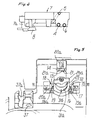
- FIG. 4 is a side view of a preferred embodiment of a cassette;
- FIG. 5 is a blown up view of a portion of the device;
- FIG. 6 is a sectional view, taken along line 6-6 of FIG. 5;
- FIG. 7 is a sectional view, taken along line 6-6 of FIG. 5, in a different step of operation than in FIG. 6;
- FIG. 8 is an exploded view of a motor assembly of the invention;
- FIGS. 9, 10 and 11 are views of three steps of the insertion of a supporting cassette in a preferred embodiment of the device.
- Referring now to the figures, cardiotomy reservoir 1 receives blood from the operating field, pouch 2 contains concentrated washed blood for reinfusion to the patient, and
container 3 contains washing liquid. Reservoir 1, pouch 2 andcontainer 3 are connected byducts cassette 7. - Within
cassette 7,ducts single tube 8, of which a portion is preferably noose-shaped by virtue of the particular shape of the end 7a of a tab 7b ofcassette 7, as best seen in FIGS. 1 and 2.Tube 8 is inserted in peristaltic pump 9 and extends tocentrifugal cell 10, which is meant to be turned by conventional means not shown in the figure. Aduct 11a for connection to awaste pouch 11 leads out fromcentrifugal cell 10. - Again referring to FIG. 3,
end portions ducts tube 8, are accommodated in thecassette 7 so that they are co-planar. Whencassette 7 is inserted in an autotransfusion device (as shown in FIGS. 1 and 2), theportions reference numerals - The
channel 12 is provided with a clamp which comprises movablesliding element 15.Sliding element 15 is preferably kept in a closed position, as shown in FIGS. 5 and 6, whereridge 15a can be held againstfixed element 16, by the action of springs 17a, 17b as best seen in FIGS. 6 and 7. - Likewise,
channel 13 is provided with a clamp which comprises a movablesliding element 18 that is preferably kept in a closed position, as shown in FIGS. 5, 6 and 7. In this closed position, ridge 18a preferably rests againstfixed element 19, by virtue of the action ofsprings 20a and 20b.Channel 14 is provided with a clamp comprising a movablesliding element 21 with aridge 21a which is preferably kept in a closed position by the action ofsprings 22a, 22b as seen in FIG. 8. - Fixed safety pins, such as
pin 23 for slidingelement 15 andpin 24 for slidingelement 18, are provided to limit the movement of the sliding elements in both directions. - Knob 25 is preferably operated manually by gripping
handle 25a.Knob 25 passes throughcassette 7 within anopening 26 provided therein, and is connected by agrub screw 27 to apivot 28, which is monolithically coupled to atriple cam 29. As seen in FIG. 8,cam 29 compriseselements 29a, 29b, 29c, which make contact preferably with sliding element portions 15b, 18b, 21b, respectively, for simultaneous actuation in a direction opposite the action of the previously mentioned springs. - The
knob 25 is provided with a lock for securingcassette 7 when it is inserted in the device. The lock may comprise a gradually slopingtooth 30.Tooth 30 is preferably shaped complementarily with respect tonotch 26a provided at the rim of opening 26 of thecassette 7. A second tooth formed byportions portions notch 26d, which allows easy passage ofhandle 25a with a wide clearance. - As seen in FIGS. 6 and 7, a motorized
cam 32 can be monolithically connected to thepivot 33.Pivot 33 is associated with anoutput shaft 34a of anelectric motor 34 and can be locked thereon by virtue of agrub screw 35. - Cam 32 is preferably inserted in the device coaxially to pivot 28 of
triple cam 29 that rests thereon so that it is centered and can rotate freely.Cam 32 is suitable to make contact with one sliding element at a time, according to an operating logic of the device described hereinafter, at theportions - A
rod 36, which is coaxial to thepivots cam 32 ifelectric motor 34 fails to operate. - Referring again to FIG. 2, a
hematocrit sensor 37 comprised withinblock 37a can be provided for accommodating terminal 7a and the corresponding tab 7b of thecassette 7. Referring to FIG. 6,optical sensors 38 working in combination withphonic wheel 39 onpivot 33 can detect the position of the motorized cam. Optionally, additional sensors can be provided within the device if desired. - The operation of the invention generally begins with the insertion of
cassette 7 in the device (shown in FIGS. 5 and 6) withknob 25 at its first stroke limit andcam 32 in a neutral position, so as to not actuate any sliding elements.Cassette 7 is positioned so that the opening 26 lies atknob 25, accommodating terminal 7a with tab 7b in theblock 37a. Tube 8 is then connected tocentrifugal cell 10 and inserted in the peristaltic pump 9.Cassette 7 preferably is prohibited from moving downward by having thesliding elements teeth - Knob 25 is then turned to bring it to its second stroke limit as shown in FIG. 10, keeping it motionless in the position that it has reached in order to overcome the action of the springs that act on the
sliding elements triple cam 29 connected thereto. This results in the dual effect of simultaneously moving the sliding elements, by virtue of the action of the triple cam, into the open position, and of arranging theteeth notches opening 26 of the cassette. -
Cassette 7 can then be moved downward to a working position by inserting theduct portions channels reference tooth 31b inserted in thecorresponding notch 26c. - When
knob 25 is released, and by virtue of the thrust applied bysliding elements triple cam 29, the knob returns to the initial position, as shown in FIG. 11, with thecassette 7 locked byteeth duct portions - After starting the rotation of
centrifugal cell 10 and starting peristaltic pump 9, the controller of the device activateselectric motor 34 which movescam 32 from the neutral position, shown in FIGS. 6 and 8, to the position shown in FIG. 7, with a movement of slidingelement 15 which produces the opening of theportion 4a, as shown in the FIG. 7, of theduct 4 that arrives from the cardiotomy reservoir 1. Blood can thus flow from cardiotomy reservoir 1 intocentrifugal cell 10, and the step for filling the cell and concentrating the red cells can be performed. Upon completion of filling and concentrating, the motor is caused to turncam 32 to close slidingelement 15 and actuate slidingelement 21 to openportion 6a ofduct 6 that arrives from the washingliquid container 3. This opensduct 6 to allow washing liquid to flow intocentrifugal cell 10. Thecentrifugal cell 10 and peristaltic pump 9 continue to turn and the step for washing the concentrated red cells is completed. The waste is sent topouch 11. - Once washing has been completed,
cell 10 stops,cam 32 is caused to rotate to actuate slidingelement 18. This results in the closure ofduct portion 6a and the opening of portion 5a ofduct 5 which is connected to the pouch 2. The peristaltic pump 9 then reverses the direction of its rotation and sends the concentrated and cleaned blood to the pouch 2 for reinfusion to the patient. The process is thus complete, andcassette 7 can then be released by actuating theknob 25. - Where technical features mentioned in any claim are followed by reference signs, those reference signs have been included for the sole purpose of increasing the intelligibility of the claims and accordingly, such reference signs do not have any limiting effect on the interpretation of each element identified by way of example by such reference signs.
Claims (15)
- An autotransfusion device, comprising:a centrifugal cell (10),a pump (9) for causing fluid flow into and out of the centrifugal cell,first, second and third clamps, each clamp including a sliding element (15,18,21) and a fixed element (16,19) defining a channel (12,13,14) therebetween, including first, second and third channels through the first, second, and third clamps, respectively, the first channel (12) being configured to accommodate a first duct (4) connectable between the centrifugal cell and a source (1) of unprocessed blood, the second channel (13) being configured to accommodate a second duct (5) connectable between the centrifugal cell and a reservoir (2) for holding processed blood and the third channel (14) being configured to accommodate a third duct (6) connectable between the centrifugal cell and a washing liquid container (3), each sliding element (15,18,21) being configured to move from a first position which impinges upon the duct (4,5,6) when accommodated in the respective channel (12,13,14) such that the lumen of that duct is substantially closed, to a second position which does not impinge upon the duct such that the lumen of that duct is substantially open,characterized in that it further comprises a cam (29,32), the cam having a first portion (29) including a plurality of extending members (29a,29b,29c) adapted to simultaneously contact and move the first, second and third sliding elements from the first position to the second position when the cam is rotated to a first position.
- The device according to Claim 1, characterized in that it further comprises movement-limiting elements (23,24) to limit the movement of the sliding elements (15,18,21).
- The device according to Claim 1, characterized in that the cam has a second portion (32) having an oblong shape adapted to selectively and individually contact the first, second and third sliding elements (15,18,21) upon rotation of the cam.
- The device according to Claim 1, characterized in that it further comprises a knob (25) coaxially positioned with respect to the cam (29,32), the knob being connected for manually turning the cam.
- The device according to Claim 1, characterized in that it further comprises a control member (34) configured for automatically moving at least one sliding element (15,18,21) at a time from a first position to a second position.
- An intraoperative autotransfusion system, comprising:a cardiotomy reservoir (1) suitable for receiving blood from a patient;a container (3) suitable for holding blood washing fluid;a reservoir (2) suitable for containing processed blood;an autotransfusion device including a centrifugal cell (10), a pump (9), and first, second, and third clamps, each clamp having a fixed element (16,19) and a sliding element (15,18,21), defining first, second and third channels (12,13,14) therebetween through the first, second and third clamps, respectively; anda cassette (7) configured for removable attachment in an operational position on the autotransfusion device, the cassette comprising:a housing;first, second, and third ducts (4,5,6) at least partially contained within the housing, the first, second and third ducts having first, second, and third lumens respectively, each duct having a first end and a second end, the first end of the first duct (4) being adapted for connection to the cardiotomy reservoir (1), the first end of the second duct (5) being adapted for connection to the reservoir (2) for containing blood processed by the autotransfusion device, the first end of the third duct (6) being adapted for connection to the container (3) for holding washing liquid, the first, second and third ducts being secured within the housing at a location such that when the cassette (7) is attached to the autotransfusion device in the operative position, the first, second and third ducts (4,5,6) are positioned within the first, second and third channels (12,13,14), respectively; anda tube (8) at least partially contained within the housing and fluidly connected to the second ends of the first, second, and thirds ducts (4,5,6), the tube having an end adapted for connection to the centrifugal cell (10);each sliding element (15,18,21) being configured to move from a first position which impinges upon the duct (4,5,6) accommodated in the respective channel (12,13,14) such that the lumen of that duct is substantially closed, to a second position which does not impinge upon the duct such that the lumen of that duct is substantially open;characterized in that it further comprises a cam (29,32), the cam having a first portion (29) including a plurality of extending members (29a,29b,29c) adapted to simultaneously contact and move the first, second and third sliding elements from the first position to the second position when the cam is rotated to a first position.
- The system according to Claim 6, characterized in that a portion of the tube (8) is looped and sized to fit within a raceway of the pump (9).
- The system according to Claim 6, characterized in that the pump (9) is connected to cause bi-directional flow through the tube (8).
- The system according to Claim 6, characterized in that it further comprises movement-limiting elements (23,24) to limit the movement of the sliding elements (15,18,21).
- The system according to Claim 6, characterized in that it further comprises a hematocrit sensor (37) comprised within a block (37a) for accommodating an end (7a) of a (7b) of the cassette (7).
- The system according to Claim 6, characterized in that the cam (29,32) has a second portion (32) having an oblong shape adapted to selectively and individually contacting the first, second and third sliding elements (15,18,21) upon rotation of the cam.
- The system according to Claim 6, characterized in that the autotransfusion device further comprises a knob (25) coaxially positioned with respect to the cam (29,32), the knob being connected for manually turning the cam.
- The system according to Claim 6, characterized in that the autotransfusion device further comprises a control member (34) configured to automatically actuate the cam (29,32).
- The system according to Claim 6, characterized in that it further comprises a motor (34) connected to rotate the cam.
- The system according to Claim 6, characterized in that it further comprises at least one optical sensor (38) to detect the position of the cam.
Applications Claiming Priority (2)
| Application Number | Priority Date | Filing Date | Title |
|---|---|---|---|
| ITMI000702 | 2000-04-03 | ||
| IT2000MI000702A IT1318444B1 (en) | 2000-04-03 | 2000-04-03 | INTRAOPERATIVE SELF-TRANSFUSION DEVICE. |
Publications (3)
| Publication Number | Publication Date |
|---|---|
| EP1142598A2 EP1142598A2 (en) | 2001-10-10 |
| EP1142598A3 EP1142598A3 (en) | 2002-06-05 |
| EP1142598B1 true EP1142598B1 (en) | 2006-06-07 |
Family
ID=11444727
Family Applications (1)
| Application Number | Title | Priority Date | Filing Date |
|---|---|---|---|
| EP01106387A Expired - Lifetime EP1142598B1 (en) | 2000-04-03 | 2001-03-19 | Intraoperative autotransfusion device |
Country Status (7)
| Country | Link |
|---|---|
| US (1) | US6632190B2 (en) |
| EP (1) | EP1142598B1 (en) |
| JP (1) | JP3610021B2 (en) |
| AU (1) | AU774621B2 (en) |
| CA (1) | CA2342652A1 (en) |
| DE (1) | DE60120267T2 (en) |
| IT (1) | IT1318444B1 (en) |
Families Citing this family (19)
| Publication number | Priority date | Publication date | Assignee | Title |
|---|---|---|---|---|
| ITMI20032341A1 (en) * | 2003-11-28 | 2005-05-29 | Dideco Spa | AUTOTRASFUSION DEVICE WITH UNIFICATION OF PROCEDURES TO BE CARRIED OUT ON THE PATIENT. |
| US7476209B2 (en) * | 2004-12-21 | 2009-01-13 | Therakos, Inc. | Method and apparatus for collecting a blood component and performing a photopheresis treatment |
| US8337411B2 (en) * | 2005-07-14 | 2012-12-25 | C. R. Bard, Inc. | Intra-abdominal pressure monitoring system |
| JP5154554B2 (en) | 2006-08-01 | 2013-02-27 | ボストン サイエンティフィック サイムド,インコーポレイテッド | Pulse inversion sequence for nonlinear imaging |
| US20090053085A1 (en) * | 2007-08-24 | 2009-02-26 | Thompson Loren M | Peristalitic pump assembly and method for attaching a cassette thereto |
| US8083503B2 (en) | 2007-09-27 | 2011-12-27 | Curlin Medical Inc. | Peristaltic pump assembly and regulator therefor |
| US8062008B2 (en) | 2007-09-27 | 2011-11-22 | Curlin Medical Inc. | Peristaltic pump and removable cassette therefor |
| US7934912B2 (en) | 2007-09-27 | 2011-05-03 | Curlin Medical Inc | Peristaltic pump assembly with cassette and mounting pin arrangement |
| US8535237B2 (en) * | 2007-10-23 | 2013-09-17 | C. R. Bard, Inc. | Continuous intra-abdominal pressure monitoring system |
| DE102010000752A1 (en) * | 2010-01-08 | 2011-07-14 | Andreas Hettich GmbH & Co. KG, 78532 | Cassette and system part which can be used in cooperation with the cassette in a centrifuge |
| GB201101550D0 (en) * | 2011-01-28 | 2011-03-16 | Rocket Medical Plc | Catheter drainage assembly |
| KR101335443B1 (en) | 2011-02-16 | 2013-11-29 | (주)에스제이글로벌 | Auto transfusion |
| EP2514451A1 (en) * | 2011-04-21 | 2012-10-24 | SIS-TER S.p.A. | Tubular insert for extra-corporeal circuit |
| KR101457584B1 (en) | 2012-10-31 | 2014-11-03 | 비앤알(주) | Autologous transfusion device |
| KR101457583B1 (en) * | 2012-10-31 | 2014-11-03 | 비앤알(주) | Autologous transfusion device |
| CN104069562B (en) * | 2014-06-27 | 2016-05-11 | 张家港龙医医疗器械有限公司 | Electronic infusion pump |
| US10653345B2 (en) | 2014-08-29 | 2020-05-19 | Fresenius Kabi Deutschland Gmbh | Blood processing apparatus comprising a holder device for a measurement device |
| DE102015102658A1 (en) * | 2015-02-25 | 2016-08-25 | B. Braun Avitum Ag | Housing front integrated blood pump |
| GB2576046B (en) | 2018-08-03 | 2023-06-14 | Advanced Electric Machines Ltd | Electrical sub-assembly and associated method of operation |
Family Cites Families (11)
| Publication number | Priority date | Publication date | Assignee | Title |
|---|---|---|---|---|
| US4069968A (en) * | 1976-11-01 | 1978-01-24 | Union Carbide Corporation | Disposable tubing harness for use with blood washing apparatus |
| US4428745A (en) * | 1982-06-21 | 1984-01-31 | Baxter Travenol Laboratories, Inc. | Flow control mechanism for a plasmapheresis assembly or the like |
| US4610781A (en) * | 1983-12-30 | 1986-09-09 | Baxter Travenol Laboratories, Inc. | Fluid processing system with flow control manifold |
| US4653719A (en) * | 1985-06-21 | 1987-03-31 | Coulter Electronics, Inc. | Fluid conduit and pinch valve for use therewith |
| US4668214A (en) * | 1986-06-09 | 1987-05-26 | Electromedics, Inc. | Method of washing red blood cells |
| US4895341A (en) * | 1988-09-30 | 1990-01-23 | Whitey Co. | Pinch valve |
| US5082025A (en) * | 1990-11-23 | 1992-01-21 | Dlp, Inc. | Antegrade-retrograde switch and occluder and system for using the same |
| US5273517A (en) * | 1991-07-09 | 1993-12-28 | Haemonetics Corporation | Blood processing method and apparatus with disposable cassette |
| US5584320A (en) * | 1994-10-31 | 1996-12-17 | Cobe Laboratories, Inc. | Multi-tube clamp actuator and mating cartridge |
| US5769385A (en) * | 1996-01-31 | 1998-06-23 | Medtronic Electromedics, Inc. | Tubing clamps for blood separating apparatus |
| JP3970331B2 (en) * | 1996-11-22 | 2007-09-05 | セラコス・インコーポレイテッド | Integrated cassette for valving, pumping and controlling fluid movement |
-
2000
- 2000-04-03 IT IT2000MI000702A patent/IT1318444B1/en active
-
2001
- 2001-03-19 EP EP01106387A patent/EP1142598B1/en not_active Expired - Lifetime
- 2001-03-19 DE DE60120267T patent/DE60120267T2/en not_active Expired - Lifetime
- 2001-03-27 US US09/819,004 patent/US6632190B2/en not_active Expired - Lifetime
- 2001-03-27 AU AU31343/01A patent/AU774621B2/en not_active Ceased
- 2001-04-02 CA CA002342652A patent/CA2342652A1/en not_active Abandoned
- 2001-04-02 JP JP2001103448A patent/JP3610021B2/en not_active Expired - Fee Related
Also Published As
| Publication number | Publication date |
|---|---|
| US6632190B2 (en) | 2003-10-14 |
| EP1142598A3 (en) | 2002-06-05 |
| AU774621B2 (en) | 2004-07-01 |
| EP1142598A2 (en) | 2001-10-10 |
| AU3134301A (en) | 2001-10-04 |
| ITMI20000702A1 (en) | 2001-10-03 |
| JP3610021B2 (en) | 2005-01-12 |
| JP2001314499A (en) | 2001-11-13 |
| US20010044601A1 (en) | 2001-11-22 |
| DE60120267T2 (en) | 2007-04-19 |
| ITMI20000702A0 (en) | 2000-04-03 |
| DE60120267D1 (en) | 2006-07-20 |
| CA2342652A1 (en) | 2001-10-03 |
| IT1318444B1 (en) | 2003-08-25 |
Similar Documents
| Publication | Publication Date | Title |
|---|---|---|
| US6632190B2 (en) | Intraoperative autotransfusion device | |
| US4428745A (en) | Flow control mechanism for a plasmapheresis assembly or the like | |
| US4425113A (en) | Flow control mechanism for a plasmaspheresis assembly or the like | |
| EP0240154B1 (en) | Pump block for interfacing irradiation chamber to photoactivation patient treatment system | |
| US6589197B1 (en) | Fluid passage change-over apparatus for medical treatment | |
| US4946434A (en) | Disposable manifold and valve | |
| JP4276431B2 (en) | Cassette with integrated separation device | |
| US4596547A (en) | Valve apparatus for photoactivation patient treatment system | |
| US5584320A (en) | Multi-tube clamp actuator and mating cartridge | |
| US10238781B2 (en) | Blood bag system and blood treatment method | |
| EP0181732B1 (en) | Automated photophoresis blood portion control apparatus | |
| CA1249756A (en) | Pump monitor for photoactivation patient treatment system | |
| CN102971021B (en) | Clip and blood bag system | |
| US4681568A (en) | Valve apparatus for photoactivation patient treatment system | |
| JPH01170469A (en) | Centrifugal separation of blood | |
| WO1994012224A1 (en) | Blood sampling system | |
| EP0239255A1 (en) | Demountable peristaltic pump for photoactivation patient treatment system | |
| US4643710A (en) | Valve apparatus for photoactivation patient treatment system | |
| JP6505837B2 (en) | Autologous blood transfusion system for separating fluid components and method of assembling the same | |
| AU593617B2 (en) | Zero insertion force socket for photoactivation patient treatment system | |
| EP0925797A1 (en) | Automatic exchanger for peritoneal dialysis | |
| EP0240152B1 (en) | Irradiation chamber for photoactivation patient treatment system | |
| US20230398275A1 (en) | Valve device, effluent bag and methods | |
| JP4681401B2 (en) | Blood component collection device | |
| CN113663210A (en) | Peritoneal dialysis pipeline current-limiting clamp |
Legal Events
| Date | Code | Title | Description |
|---|---|---|---|
| PUAI | Public reference made under article 153(3) epc to a published international application that has entered the european phase |
Free format text: ORIGINAL CODE: 0009012 |
|
| AK | Designated contracting states |
Kind code of ref document: A2 Designated state(s): AT BE CH CY DE DK ES FI FR GB GR IE IT LI LU MC NL PT SE TR |
|
| AX | Request for extension of the european patent |
Free format text: AL;LT;LV;MK;RO;SI |
|
| PUAL | Search report despatched |
Free format text: ORIGINAL CODE: 0009013 |
|
| AK | Designated contracting states |
Kind code of ref document: A3 Designated state(s): AT BE CH CY DE DK ES FI FR GB GR IE IT LI LU MC NL PT SE TR |
|
| AX | Request for extension of the european patent |
Free format text: AL;LT;LV;MK;RO;SI |
|
| 17P | Request for examination filed |
Effective date: 20021121 |
|
| AKX | Designation fees paid |
Designated state(s): DE FR GB IT NL |
|
| 17Q | First examination report despatched |
Effective date: 20040428 |
|
| RAP1 | Party data changed (applicant data changed or rights of an application transferred) |
Owner name: DIDECO S.R.L. |
|
| GRAP | Despatch of communication of intention to grant a patent |
Free format text: ORIGINAL CODE: EPIDOSNIGR1 |
|
| GRAS | Grant fee paid |
Free format text: ORIGINAL CODE: EPIDOSNIGR3 |
|
| RAP1 | Party data changed (applicant data changed or rights of an application transferred) |
Owner name: SORIN GROUP ITALIA S.R.L. |
|
| GRAA | (expected) grant |
Free format text: ORIGINAL CODE: 0009210 |
|
| AK | Designated contracting states |
Kind code of ref document: B1 Designated state(s): DE FR GB IT NL |
|
| PG25 | Lapsed in a contracting state [announced via postgrant information from national office to epo] |
Ref country code: IT Free format text: LAPSE BECAUSE OF FAILURE TO SUBMIT A TRANSLATION OF THE DESCRIPTION OR TO PAY THE FEE WITHIN THE PRESCRIBED TIME-LIMIT;WARNING: LAPSES OF ITALIAN PATENTS WITH EFFECTIVE DATE BEFORE 2007 MAY HAVE OCCURRED AT ANY TIME BEFORE 2007. THE CORRECT EFFECTIVE DATE MAY BE DIFFERENT FROM THE ONE RECORDED. Effective date: 20060607 |
|
| REG | Reference to a national code |
Ref country code: GB Ref legal event code: FG4D |
|
| REF | Corresponds to: |
Ref document number: 60120267 Country of ref document: DE Date of ref document: 20060720 Kind code of ref document: P |
|
| ET | Fr: translation filed | ||
| PLBE | No opposition filed within time limit |
Free format text: ORIGINAL CODE: 0009261 |
|
| STAA | Information on the status of an ep patent application or granted ep patent |
Free format text: STATUS: NO OPPOSITION FILED WITHIN TIME LIMIT |
|
| 26N | No opposition filed |
Effective date: 20070308 |
|
| REG | Reference to a national code |
Ref country code: FR Ref legal event code: PLFP Year of fee payment: 15 |
|
| REG | Reference to a national code |
Ref country code: FR Ref legal event code: PLFP Year of fee payment: 16 |
|
| REG | Reference to a national code |
Ref country code: FR Ref legal event code: PLFP Year of fee payment: 17 |
|
| REG | Reference to a national code |
Ref country code: FR Ref legal event code: PLFP Year of fee payment: 18 |
|
| PGFP | Annual fee paid to national office [announced via postgrant information from national office to epo] |
Ref country code: DE Payment date: 20180306 Year of fee payment: 18 Ref country code: NL Payment date: 20180314 Year of fee payment: 18 Ref country code: GB Payment date: 20180314 Year of fee payment: 18 |
|
| PGFP | Annual fee paid to national office [announced via postgrant information from national office to epo] |
Ref country code: IT Payment date: 20180321 Year of fee payment: 18 Ref country code: FR Payment date: 20180223 Year of fee payment: 18 |
|
| REG | Reference to a national code |
Ref country code: DE Ref legal event code: R119 Ref document number: 60120267 Country of ref document: DE |
|
| REG | Reference to a national code |
Ref country code: NL Ref legal event code: MM Effective date: 20190401 |
|
| GBPC | Gb: european patent ceased through non-payment of renewal fee |
Effective date: 20190319 |
|
| PG25 | Lapsed in a contracting state [announced via postgrant information from national office to epo] |
Ref country code: GB Free format text: LAPSE BECAUSE OF NON-PAYMENT OF DUE FEES Effective date: 20190319 Ref country code: NL Free format text: LAPSE BECAUSE OF NON-PAYMENT OF DUE FEES Effective date: 20190401 Ref country code: DE Free format text: LAPSE BECAUSE OF NON-PAYMENT OF DUE FEES Effective date: 20191001 |
|
| PG25 | Lapsed in a contracting state [announced via postgrant information from national office to epo] |
Ref country code: FR Free format text: LAPSE BECAUSE OF NON-PAYMENT OF DUE FEES Effective date: 20190331 Ref country code: IT Free format text: LAPSE BECAUSE OF NON-PAYMENT OF DUE FEES Effective date: 20190319 |