EP1139702B1 - Protection device for an electrical component - Google Patents
Protection device for an electrical component Download PDFInfo
- Publication number
- EP1139702B1 EP1139702B1 EP01302376A EP01302376A EP1139702B1 EP 1139702 B1 EP1139702 B1 EP 1139702B1 EP 01302376 A EP01302376 A EP 01302376A EP 01302376 A EP01302376 A EP 01302376A EP 1139702 B1 EP1139702 B1 EP 1139702B1
- Authority
- EP
- European Patent Office
- Prior art keywords
- base
- protection device
- terminal cap
- battery
- electrical component
- Prior art date
- Legal status (The legal status is an assumption and is not a legal conclusion. Google has not performed a legal analysis and makes no representation as to the accuracy of the status listed.)
- Expired - Lifetime
Links
- 230000001681 protective effect Effects 0.000 claims abstract description 30
- 239000012790 adhesive layer Substances 0.000 claims description 12
- 239000012212 insulator Substances 0.000 claims description 12
- 230000002093 peripheral effect Effects 0.000 claims description 8
- 239000007769 metal material Substances 0.000 claims description 4
- 239000002210 silicon-based material Substances 0.000 claims description 3
- 238000000034 method Methods 0.000 abstract description 10
- 239000000463 material Substances 0.000 description 20
- 239000000853 adhesive Substances 0.000 description 13
- 230000001070 adhesive effect Effects 0.000 description 13
- 125000006850 spacer group Chemical group 0.000 description 6
- 238000000465 moulding Methods 0.000 description 5
- 230000000712 assembly Effects 0.000 description 4
- 238000000429 assembly Methods 0.000 description 4
- 238000003466 welding Methods 0.000 description 4
- 238000004519 manufacturing process Methods 0.000 description 3
- 241001272720 Medialuna californiensis Species 0.000 description 2
- 239000004696 Poly ether ether ketone Substances 0.000 description 2
- 229920004695 VICTREX™ PEEK Polymers 0.000 description 2
- 239000004760 aramid Substances 0.000 description 2
- 229920003235 aromatic polyamide Polymers 0.000 description 2
- JUPQTSLXMOCDHR-UHFFFAOYSA-N benzene-1,4-diol;bis(4-fluorophenyl)methanone Chemical compound OC1=CC=C(O)C=C1.C1=CC(F)=CC=C1C(=O)C1=CC=C(F)C=C1 JUPQTSLXMOCDHR-UHFFFAOYSA-N 0.000 description 2
- 239000003792 electrolyte Substances 0.000 description 2
- 229920006351 engineering plastic Polymers 0.000 description 2
- 239000004763 nomex Substances 0.000 description 2
- 229920002312 polyamide-imide Polymers 0.000 description 2
- 229920002530 polyetherether ketone Polymers 0.000 description 2
- 239000000758 substrate Substances 0.000 description 2
- 239000004593 Epoxy Substances 0.000 description 1
- 229920000106 Liquid crystal polymer Polymers 0.000 description 1
- 239000004977 Liquid-crystal polymers (LCPs) Substances 0.000 description 1
- 239000004952 Polyamide Substances 0.000 description 1
- 239000004962 Polyamide-imide Substances 0.000 description 1
- 229920004003 Torlon® 4203 Polymers 0.000 description 1
- 229920013651 Zenite Polymers 0.000 description 1
- 230000001154 acute effect Effects 0.000 description 1
- 230000003247 decreasing effect Effects 0.000 description 1
- 239000012777 electrically insulating material Substances 0.000 description 1
- 238000005516 engineering process Methods 0.000 description 1
- 239000012943 hotmelt Substances 0.000 description 1
- 238000001746 injection moulding Methods 0.000 description 1
- 229920002647 polyamide Polymers 0.000 description 1
- 229920000728 polyester Polymers 0.000 description 1
- 229920001296 polysiloxane Polymers 0.000 description 1
- 238000000926 separation method Methods 0.000 description 1
- BFKJFAAPBSQJPD-UHFFFAOYSA-N tetrafluoroethene Chemical group FC(F)=C(F)F BFKJFAAPBSQJPD-UHFFFAOYSA-N 0.000 description 1
- PGNWIWKMXVDXHP-UHFFFAOYSA-L zinc;1,3-benzothiazole-2-thiolate Chemical compound [Zn+2].C1=CC=C2SC([S-])=NC2=C1.C1=CC=C2SC([S-])=NC2=C1 PGNWIWKMXVDXHP-UHFFFAOYSA-L 0.000 description 1
Images



Classifications
-
- H—ELECTRICITY
- H01—ELECTRIC ELEMENTS
- H01M—PROCESSES OR MEANS, e.g. BATTERIES, FOR THE DIRECT CONVERSION OF CHEMICAL ENERGY INTO ELECTRICAL ENERGY
- H01M50/00—Constructional details or processes of manufacture of the non-active parts of electrochemical cells other than fuel cells, e.g. hybrid cells
- H01M50/10—Primary casings; Jackets or wrappings
- H01M50/147—Lids or covers
- H01M50/148—Lids or covers characterised by their shape
- H01M50/154—Lid or cover comprising an axial bore for receiving a central current collector
-
- H—ELECTRICITY
- H01—ELECTRIC ELEMENTS
- H01M—PROCESSES OR MEANS, e.g. BATTERIES, FOR THE DIRECT CONVERSION OF CHEMICAL ENERGY INTO ELECTRICAL ENERGY
- H01M10/00—Secondary cells; Manufacture thereof
- H01M10/42—Methods or arrangements for servicing or maintenance of secondary cells or secondary half-cells
-
- H—ELECTRICITY
- H01—ELECTRIC ELEMENTS
- H01M—PROCESSES OR MEANS, e.g. BATTERIES, FOR THE DIRECT CONVERSION OF CHEMICAL ENERGY INTO ELECTRICAL ENERGY
- H01M10/00—Secondary cells; Manufacture thereof
- H01M10/42—Methods or arrangements for servicing or maintenance of secondary cells or secondary half-cells
- H01M10/425—Structural combination with electronic components, e.g. electronic circuits integrated to the outside of the casing
-
- H—ELECTRICITY
- H01—ELECTRIC ELEMENTS
- H01M—PROCESSES OR MEANS, e.g. BATTERIES, FOR THE DIRECT CONVERSION OF CHEMICAL ENERGY INTO ELECTRICAL ENERGY
- H01M10/00—Secondary cells; Manufacture thereof
- H01M10/42—Methods or arrangements for servicing or maintenance of secondary cells or secondary half-cells
- H01M10/48—Accumulators combined with arrangements for measuring, testing or indicating the condition of cells, e.g. the level or density of the electrolyte
-
- H—ELECTRICITY
- H01—ELECTRIC ELEMENTS
- H01M—PROCESSES OR MEANS, e.g. BATTERIES, FOR THE DIRECT CONVERSION OF CHEMICAL ENERGY INTO ELECTRICAL ENERGY
- H01M50/00—Constructional details or processes of manufacture of the non-active parts of electrochemical cells other than fuel cells, e.g. hybrid cells
- H01M50/10—Primary casings; Jackets or wrappings
- H01M50/147—Lids or covers
-
- H—ELECTRICITY
- H01—ELECTRIC ELEMENTS
- H01M—PROCESSES OR MEANS, e.g. BATTERIES, FOR THE DIRECT CONVERSION OF CHEMICAL ENERGY INTO ELECTRICAL ENERGY
- H01M50/00—Constructional details or processes of manufacture of the non-active parts of electrochemical cells other than fuel cells, e.g. hybrid cells
- H01M50/50—Current conducting connections for cells or batteries
- H01M50/572—Means for preventing undesired use or discharge
- H01M50/574—Devices or arrangements for the interruption of current
- H01M50/581—Devices or arrangements for the interruption of current in response to temperature
-
- H—ELECTRICITY
- H01—ELECTRIC ELEMENTS
- H01M—PROCESSES OR MEANS, e.g. BATTERIES, FOR THE DIRECT CONVERSION OF CHEMICAL ENERGY INTO ELECTRICAL ENERGY
- H01M6/00—Primary cells; Manufacture thereof
- H01M6/50—Methods or arrangements for servicing or maintenance, e.g. for maintaining operating temperature
- H01M6/5044—Cells or batteries structurally combined with cell condition indicating means
- H01M6/505—Cells combined with indicating means for external visualization of the condition, e.g. by change of colour or of light intensity
-
- H—ELECTRICITY
- H01—ELECTRIC ELEMENTS
- H01M—PROCESSES OR MEANS, e.g. BATTERIES, FOR THE DIRECT CONVERSION OF CHEMICAL ENERGY INTO ELECTRICAL ENERGY
- H01M50/00—Constructional details or processes of manufacture of the non-active parts of electrochemical cells other than fuel cells, e.g. hybrid cells
- H01M50/10—Primary casings; Jackets or wrappings
- H01M50/147—Lids or covers
- H01M50/166—Lids or covers characterised by the methods of assembling casings with lids
-
- Y—GENERAL TAGGING OF NEW TECHNOLOGICAL DEVELOPMENTS; GENERAL TAGGING OF CROSS-SECTIONAL TECHNOLOGIES SPANNING OVER SEVERAL SECTIONS OF THE IPC; TECHNICAL SUBJECTS COVERED BY FORMER USPC CROSS-REFERENCE ART COLLECTIONS [XRACs] AND DIGESTS
- Y02—TECHNOLOGIES OR APPLICATIONS FOR MITIGATION OR ADAPTATION AGAINST CLIMATE CHANGE
- Y02E—REDUCTION OF GREENHOUSE GAS [GHG] EMISSIONS, RELATED TO ENERGY GENERATION, TRANSMISSION OR DISTRIBUTION
- Y02E60/00—Enabling technologies; Technologies with a potential or indirect contribution to GHG emissions mitigation
- Y02E60/10—Energy storage using batteries
Definitions
- the present invention relates generally to devices for protecting an electrical component. More specifically, the present invention relates to a protection device for an electrical component connected to a battery.
- Such prior art devices include a cylindrical spacer ring and a terminal cap.
- the spacer ring is positioned on an end of the battery.
- the electrical component resides within the spacer ring, and is electrically connected to the battery by at least one, and sometimes two electrical, leads. Another electrical lead of the electrical component is connected to the terminal cap.
- an electrically insulating half-moon disk is placed on the battery header.
- the electrical component is placed on the half-moon disk.
- the first electrical lead of the electrical component is welded to a terminal pin of the battery.
- a second electrical lead of the electrical component is welded to the header of the battery.
- the spacer ring is placed on the battery so as to encircle the electrical component.
- the volume within the spacer ring and above the battery, which is not occupied by the electrical component is filled with an adhesive material, which may be a polyamide material such as AD-TECH 700 manufactured by Adhesive Technologies, Inc.
- the electrical component is substantially covered with the adhesive material. Only a portion of an electrical lead of the electrical component extends out of and is not entirely covered with the adhesive material.
- an insulating disk is placed partially into the adhesive material, and a terminal cap is placed over the insulating disk, as well as that portion of the adhesive material which is not covered by the insulating disk. Finally, the exposed electrical lead of the electrical component extending from the adhesive material is welded to the terminal cap.
- Such prior art assemblies have disadvantages. For example, they are not able to withstand temperatures of 200 C or more. Adhesive material used in the prior art assemblies fail at temperatures around or below 170°C. In addition methods of making such prior art assemblies take a great amount of time are costly and are messy, primarily due to the adhesive material. Furthermore, a substantial amount of scrap material is generated in manufacturing such prior art assemblies. Finally, if the electrical component does not operate properly, removal and replacement with a properly operating electrical component is difficult, if not impossible.
- Another object of the present invention is to provide a protection device and method which permits but does not require the use of adhesive material when assembling the battery and an electrical component.
- Yet another object of the present invention is to provide a protection device that permits replacement of an improperly operating electrical component.
- the foregoing objectives are realized by the present invention, which is a protection device for an electrical component that has a protective housing and a terminal cap.
- the protective housing has a base with a contact hole therethrough for accommodating an electrical terminal pin.
- a projecting shoulder extends from the base to a first distance from the base.
- a retaining clip extends from the base to a second distance from the base, the second distance being greater than the first distance.
- a connecting wall connects to the projecting shoulder and the retaining clip.
- the terminal cap has a first side and a second side, and in use, at least part of the first side of the terminal cap contacts the projecting shoulder and at least part of the second side of the terminal cap contacts the retaining clip to thereby capture the terminal cap between the projecting shoulder and the retaining clip.
- the projecting shoulder of the device of the invention may have a rib.
- a battery and an electrical component are assembled.
- the method begins by providing a battery having a terminal pin, and providing a protective housing having a base with a contact hole therethrough.
- the protective housing is mounted on the battery so that the terminal pin extends into the contact hole.
- an electrical component is provided on the base and electrically connected to the terminal pin.
- a terminal cap is provided in contact with the protective housing and connected to the electrical component.
- FIGs 1 and 2 show a protection device 10 according to the present invention in the assembled form.
- the protection device 10 includes a protective housing 11 (shown also in Figures 3, 4 and 5) having a base 12. As shown in Figures 3, 4 and 5, extending from a primary surface 14 of the base 12 is a projecting shoulder 16 having a curved side wall 17 extending to an upper surface 18, which is generally parallel to the primary surface 14.
- the curved side wall 17 extends generally perpendicularly from the primary surface 14 so that the upper surface 18 is at a first distance 19 from the primary surface 14.
- the protective housing 11 also has a retaining clip 22 having an arcuate side wall 23 terminating in a hook portion 24.
- the hook portion 24 provides a retaining ledge 24A, which is generally parallel to the primary surface 14.
- the retaining ledge 24A is spaced from the primary surface 14 a second distance 25 above the primary surface 14. As shown in Figure 4, the second distance 25 is greater than the first distance 19.
- a material which is suitable for the protective housing 11 is Victrex (PEEK) 450-G manufactured by Victrex USA Inc. of Westchester, Pennsylvania, or alternatively a polyamide-imide available from DSM Engineering Plastic Products, Inc. of Reading, Pennsylvania as Torlon 4203 PAI. Also suitable for the protective housing 11 and available from DSM Engineering Plastic Products, Inc. is a material marketed under the name KetronTM PEEK 1000.
- Another material suitable for the protective housing 11 is liquid crystal polymer, commonly known as Zenite, and available from E.I. du Pont de Nemours and Company.
- molding orifices 27 are preferably provided in the base 12.
- the molding orifices 27 allow a portion of a mold to extend through the base 12 to form the retaining ledge 24A at the second distance 25. Once the retaining clips 22 are formed, the mold is withdrawn through the molding orifices 27.
- the protection device 10 also includes a terminal cap 28. As shown in Figures 1 and 2, a portion of a first side 31 of the terminal cap 28 rests on the upper surface 18 of the projecting shoulder 16. In addition, a portion of a second side 34 of the terminal cap 28 contacts the retaining ledge 24A of the retaining clip 22. The difference between the first distance 19 and the second distance 25 may be such that the terminal cap 28 is firmly held against the upper surface 18 of the projecting shoulder 16 and the retaining ledge 24A of the retaining clip 22, as shown in Figure 2.
- FIGS 5 and 6 show the relative position of an electrical component 37 with respect to the protection device 10.
- the electrical component 37 may include a fuse 40 and a diode 43 mounted on an insulating substrate 46. Those skilled in the art will recognize that the diode 43 and/or substrate 46 may be omitted depending on the particular intended application.
- a terminal pin 49 of a battery 52 extends through a contact hole 55 in the base 12 and is connected to a first lead 58 of the electrical component 37 by welding the first lead 58 to the terminal pin 49.
- a second lead 61 is connected to a header 64 of the battery 52 by passing the second lead 61 through one of the molding orifices 27.
- the second lead 61 may be electrically connected to the header 64 by welding.
- the present invention may include a compressible pad 70 for holding the electrical component 37 firmly in place.
- the compressible pad 70 contacts and is compressed between portions of the electrical component 37 and portions of the terminal cap 28.
- the compressible pad 70 may serve also to hold the terminal cap 28 firmly against the retaining clip 22 and off of projecting shoulder 16.
- an adhesive type material similar to that used in the prior art may be used.
- the compressible pad 70 is preferred because it reduces assembly costs and mess associated with the prior art adhesive material.
- the compressible pad 70 is a material which can withstand at least about 200°C, and is preferably a silicone based material.
- a silicone based material which is suitable for use in the compressible pad 70 is available from Furon Company of New Haven, Connecticut as product number R10470 and referred to by the trademark COHRlastic®.
- the protective housing 11 may be further prevented from rotating by providing a shelf 73, an edge 75 and a wrap 77.
- the shelf 73 is provided by positioning the retaining clip 22 to extend from a location on the primary surface 14 which is set back from a peripheral rim 83 of the base 12.
- the shelf 73 is defined by the intersections of the retaining clip 22 and the peripheral rim 83 with the primary surface 14.
- the shelf 73 is provided by positioning the projecting shoulder 16 to extend from a location on the primary surface 14 which is set back from the peripheral rim 83 so as to define the shelf 73 formed by the intersections of the projecting shoulder 16 and the peripheral rim 83 with the primary surface 14.
- the intersection of the shelf 73 and the peripheral rim 83 defines the edge 75.
- a wrap 77 When the base 12 is provided with the shelf 73, a wrap 77, shown in Figure 1, may be placed around a portion of the header 64 and a portion of the protective housing 11, including the shelf 73.
- the shelf 73 provides a discontinuity in the otherwise cylindrical surface covered by the wrap 77.
- the edge 75 extends into the wrap 77, thereby preventing the base 12 from rotating relative to the header 64 when the wrap 77 is sufficiently tight around the base 12 and battery 52.
- the wrap 77 is preferably made from an electrically insulating material such as polymerized tetrafluoroethylene or polyester. The wrap 77 may be heat-shrunk into the proper position.
- electrolyte is introduced through the header 64 using a fill hole. Once the battery 52 has the proper amount of electrolyte inside, the fill hole is closed usually by welding a metallic material to the header 64.
- the metallic material often extends from the header 64 as a metallic projection 86, shown in Figure 5. Although the metallic projection 86 does not extend far beyond the, header 64, since it is desirable to have the base 12 firmly supported by the header 64, an accommodating orifice 88 may be positioned in the base 12 to accommodate the metallic projection 86 therein.
- a means for fastening may be provided.
- the means for fastening may be a tinnerman fastener 92 which contacts the base 12, and attaches to a portion of the terminal pin 49 extending through the contact hole 55.
- the terminal cap 28 is preferably electrically conductive.
- a third lead 95 shown in Figures 2, 5 and 6, is electrically connected to the terminal cap 28.
- the third lead 95 may be electrically connected to the terminal cap 28 by welding.
- Figure 8 shows an alternative embodiment of the protective housing 11.
- interstitial side walls 96 of the projecting shoulders 16 and retaining clips 22 are tapered so that the interstitial side walls 96 do not form a right angle with the primary surface 14, and instead form an acute angle ⁇ with the primary surface 14.
- rounded edges 97 on the projecting shoulders 16 and retaining clips 22 A mold having rounded edges 97 is easier to construct.
- Figure 8 shows ribs 98 on the retaining clips 22. The ribs 98 permit the material used to form the protective housing 22 to flow within the mold to completely and consistently form the retaining clips 22.
- FIG. 9 shows steps of a method according to the present invention in which a battery and an electrical component, such as those described above, are assembled.
- the method begins by providing (step 100) a battery having a terminal pin, and providing (step 103) a protective housing having a base with a contact hole therethrough, a projecting shoulder and a retaining clip.
- the base is mounted (step 106) on the battery so that the terminal pin extends into the contact hole.
- an electrical component is provided (step 109) on the base and electrically connected (step 112) to the terminal pin.
- a terminal cap is provided (step 118) in contact with the projecting shoulder and the retaining clip, and the terminal cap is electrically connected (step 121) to the electrical component.
- a compressible pad is provided (step 115) in contact with the electrical component.
- Figures 10 and 11 show an alternative embodiment of the present invention in which connecting walls 200 connect to the arcuate side wall 23 of the retaining clip 22, and connect to the curved side wall 17 of the projecting shoulder 16.
- the connecting walls 200 stiffen the retaining clips 22.
- Figure 11 also shows a variation on the projecting shoulder 16 described above.
- some of the projecting shoulders 16 have ribs 205 formed on the curved side wall 17. It should be noted that any number of the shoulders 16 may have ribs 205.
- the ribs 205 increase the size of the upper surface 18, and thereby prevent part of the terminal cap 28 from moving too close to the primary surface 14.
- Figure 12 shows an alternative embodiment of the present invention in which a gasket 300 is placed between the base 12 and the header 64.
- the gasket 300 allows the protection 10 to be seated firmly on the header 64, even when the header 64 or the base 12 has irregularities in it.
- a preferred gasket 300 is made from an aramid insulating paper, such as Nomex TM , and is preferably approximately 0.013 inches thick.
- the gasket 300 may have one or more adhesive layers for bonding to the header 64 and/or the base 12.
- the gasket 300 may have a first adhesive layer 302 for bonding to the header 64, and may have a second adhesive layer 303 for bonding to the base 12. It should be noted that the thickness of the gasket 300 and the adhesive layers 302, 303 shown in Figure 12 are not drawn to scale in order that the gasket 300 and the adhesive layers 302, 303 can be more easily understood.
- Figure 13 shows an insulator 310 placed between the first side 31 of the terminal cap 28 and the electrical component 37.
- the insulator 310 is preferably made from an aramid insulating paper, such as Nomex TM .
- the insulator 310 may have an adhesive layer on one or more sides.
- the insulator 310 may have an adhesive layer 315 for bonding the insulator 310 to the first side 31 of the terminal cap 28.
- the insulator 310 is approximately 0.008 inches thick. It should be noted that Figure 13 is not to scale with regard to the thickness of the insulator 310 and adhesive layer 315, so that the features of the insulator and adhesive layer 315 can be more easily understood.
Landscapes
- Chemical & Material Sciences (AREA)
- Chemical Kinetics & Catalysis (AREA)
- Electrochemistry (AREA)
- General Chemical & Material Sciences (AREA)
- Engineering & Computer Science (AREA)
- Manufacturing & Machinery (AREA)
- Microelectronics & Electronic Packaging (AREA)
- Connection Of Batteries Or Terminals (AREA)
- Battery Mounting, Suspending (AREA)
- Apparatus For Radiation Diagnosis (AREA)
- Emergency Protection Circuit Devices (AREA)
- Fuses (AREA)
Abstract
Description
- The present invention relates generally to devices for protecting an electrical component. More specifically, the present invention relates to a protection device for an electrical component connected to a battery.
- In the prior art, there are devices for protecting an electrical component, such as a fuse and diode assembly, connected to and mounted on a battery. Such prior art devices include a cylindrical spacer ring and a terminal cap. The spacer ring is positioned on an end of the battery. The electrical component resides within the spacer ring, and is electrically connected to the battery by at least one, and sometimes two electrical, leads. Another electrical lead of the electrical component is connected to the terminal cap.
- To assemble the battery, the electrical component and the prior art spacer ring, an electrically insulating half-moon disk is placed on the battery header. Next, the electrical component is placed on the half-moon disk. Then the first electrical lead of the electrical component is welded to a terminal pin of the battery. If provided, a second electrical lead of the electrical component is welded to the header of the battery. Next, the spacer ring is placed on the battery so as to encircle the electrical component. Then the volume within the spacer ring and above the battery, which is not occupied by the electrical component, is filled with an adhesive material, which may be a polyamide material such as AD-TECH 700 manufactured by Adhesive Technologies, Inc. of Hampton, New Hampshire (sometimes referred to as "hot-melt"), or which may be an epoxy or silicone material. In doing so, the electrical component is substantially covered with the adhesive material. Only a portion of an electrical lead of the electrical component extends out of and is not entirely covered with the adhesive material. Next, an insulating disk is placed partially into the adhesive material, and a terminal cap is placed over the insulating disk, as well as that portion of the adhesive material which is not covered by the insulating disk. Finally, the exposed electrical lead of the electrical component extending from the adhesive material is welded to the terminal cap.
- Such prior art assemblies have disadvantages. For example, they are not able to withstand temperatures of 200 C or more. Adhesive material used in the prior art assemblies fail at temperatures around or below 170°C. In addition methods of making such prior art assemblies take a great amount of time are costly and are messy, primarily due to the adhesive material. Furthermore, a substantial amount of scrap material is generated in manufacturing such prior art assemblies. Finally, if the electrical component does not operate properly, removal and replacement with a properly operating electrical component is difficult, if not impossible.
- Accordingly, it is an object of the present invention to provide a protection device which can withstand temperatures of 200 C or more.
- Another object of the present invention is to provide a protection device and method which permits but does not require the use of adhesive material when assembling the battery and an electrical component.
- Yet another object of the present invention is to provide a protection device that permits replacement of an improperly operating electrical component.
- The foregoing objectives are realized by the present invention, which is a protection device for an electrical component that has a protective housing and a terminal cap. The protective housing has a base with a contact hole therethrough for accommodating an electrical terminal pin. A projecting shoulder extends from the base to a first distance from the base. In addition, a retaining clip extends from the base to a second distance from the base, the second distance being greater than the first distance. A connecting wall connects to the projecting shoulder and the retaining clip. The terminal cap has a first side and a second side, and in use, at least part of the first side of the terminal cap contacts the projecting shoulder and at least part of the second side of the terminal cap contacts the retaining clip to thereby capture the terminal cap between the projecting shoulder and the retaining clip.
- The projecting shoulder of the device of the invention may have a rib.
- In a method according to the present invention, a battery and an electrical component are assembled. The method begins by providing a battery having a terminal pin, and providing a protective housing having a base with a contact hole therethrough. The protective housing is mounted on the battery so that the terminal pin extends into the contact hole. Next, an electrical component is provided on the base and electrically connected to the terminal pin. Finally, a terminal cap is provided in contact with the protective housing and connected to the electrical component.
- Other objects and advantages of the present invention will become apparent to those skilled in the art from the following detailed description read in conjunction with the attached drawings and claims appended hereto.
- For a fuller understanding of the nature and objects of the invention, reference should be made to the following detailed description taken in conjunction with the accompanying drawings, in which:
- Figure 1 is a partially cross sectioned side view of a protection device according to the present invention mounted on the header of a battery;
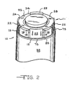
- Figure 2 is a perspective view of the protection device shown in Figure 1;
- Figure 3 is a top view of the protective housing according to the present invention;
- Figure 4 is a cross sectional view of the protective housing taken along line 4--4 shown in Figure 3;
- Figure 5 is an exploded perspective view of the protection device and battery shown in Figure 1;
- Figure 6 is a perspective view of the battery, protective housing and electrical component shown in Figure 1;
- Figure 7 is a partially cross sectioned side view of the protective housing taken along line 7--7 shown in Figure 3;
- Figure 8 is a perspective view of an alternative embodiment of the protective housing;
- Figure 9 is a flow chart of a method according to the present invention;
- Figure 10 is a perspective view of an alternative embodiment of the present invention;
- Figure 11 is an exploded perspective view of the embodiment shown in Figure 10;
- Figure 12 is an exploded perspective view of an another embodiment of the present invention; and
- Figure 13 is an exploded perspective view of yet another embodiment of the present invention.
- Figures 1 and 2 show a
protection device 10 according to the present invention in the assembled form. Theprotection device 10 includes a protective housing 11 (shown also in Figures 3, 4 and 5) having abase 12. As shown in Figures 3, 4 and 5, extending from aprimary surface 14 of thebase 12 is a projectingshoulder 16 having acurved side wall 17 extending to anupper surface 18, which is generally parallel to theprimary surface 14. Thecurved side wall 17 extends generally perpendicularly from theprimary surface 14 so that theupper surface 18 is at afirst distance 19 from theprimary surface 14. - The
protective housing 11 also has a retainingclip 22 having anarcuate side wall 23 terminating in ahook portion 24. Thehook portion 24 provides aretaining ledge 24A, which is generally parallel to theprimary surface 14. The retainingledge 24A is spaced from the primary surface 14 asecond distance 25 above theprimary surface 14. As shown in Figure 4, thesecond distance 25 is greater than thefirst distance 19. - A material which is suitable for the
protective housing 11 is Victrex (PEEK) 450-G manufactured by Victrex USA Inc. of Westchester, Pennsylvania, or alternatively a polyamide-imide available from DSM Engineering Plastic Products, Inc. of Reading, Pennsylvania as Torlon 4203 PAI. Also suitable for theprotective housing 11 and available from DSM Engineering Plastic Products, Inc. is a material marketed under the name KetronTM PEEK 1000. Another material suitable for theprotective housing 11 is liquid crystal polymer, commonly known as Zenite, and available from E.I. du Pont de Nemours and Company. - There are preferably at least three separate projecting
shoulders 16 and at least three separate retaining clips 22. A measure of safety can be provided if four separate retaining clips 22 are provided, as shown in Figures 2, 3 and 5. As shown in Figures 2, 3, 5 and 6, a plurality of projectingshoulders 16 and retainingclips 22 may be provided in an alternating configuration about the circumference of thebase 14. - To facilitate manufacturing the retaining clips 22, for example by injection molding,
molding orifices 27 are preferably provided in thebase 12. The molding orifices 27 allow a portion of a mold to extend through the base 12 to form the retainingledge 24A at thesecond distance 25. Once the retaining clips 22 are formed, the mold is withdrawn through themolding orifices 27. - The
protection device 10 according to the present invention also includes aterminal cap 28. As shown in Figures 1 and 2, a portion of afirst side 31 of theterminal cap 28 rests on theupper surface 18 of the projectingshoulder 16. In addition, a portion of asecond side 34 of theterminal cap 28 contacts the retainingledge 24A of the retainingclip 22. The difference between thefirst distance 19 and thesecond distance 25 may be such that theterminal cap 28 is firmly held against theupper surface 18 of the projectingshoulder 16 and the retainingledge 24A of the retainingclip 22, as shown in Figure 2. - Figures 5 and 6 show the relative position of an
electrical component 37 with respect to theprotection device 10. Theelectrical component 37 may include afuse 40 and adiode 43 mounted on an insulatingsubstrate 46. Those skilled in the art will recognize that thediode 43 and/orsubstrate 46 may be omitted depending on the particular intended application. Aterminal pin 49 of abattery 52 extends through acontact hole 55 in thebase 12 and is connected to afirst lead 58 of theelectrical component 37 by welding thefirst lead 58 to theterminal pin 49. When thediode 43 is present in theelectrical component 37, sometimes asecond lead 61 is connected to aheader 64 of thebattery 52 by passing thesecond lead 61 through one of themolding orifices 27. Thesecond lead 61 may be electrically connected to theheader 64 by welding. - As shown in Figures 1 and 5, the present invention may include a
compressible pad 70 for holding theelectrical component 37 firmly in place. As shown in Figure 1, once theterminal cap 28 contacts the retainingclip 22, thecompressible pad 70 contacts and is compressed between portions of theelectrical component 37 and portions of theterminal cap 28. Thecompressible pad 70 may serve also to hold theterminal cap 28 firmly against the retainingclip 22 and off of projectingshoulder 16. Those skilled in the art will recognize that by placing a retaining ring around the retaining clips 22 and projectingshoulders 16, or by using a fast curing or highly viscous adhesive material, an adhesive type material similar to that used in the prior art may be used. Thecompressible pad 70, however, is preferred because it reduces assembly costs and mess associated with the prior art adhesive material. - The
compressible pad 70 is a material which can withstand at least about 200°C, and is preferably a silicone based material. A silicone based material which is suitable for use in thecompressible pad 70 is available from Furon Company of New Haven, Connecticut as product number R10470 and referred to by the trademark COHRlastic®. - It is important to prevent the
protective housing 11 from rotating relative to thebattery 52 so that the first and second leads 58, 61 are not detached from theterminal pin 49 andheader 64, respectively. Although theprotective housing 11 is prevented to some extent from rotating by thefirst lead 58 connected to theterminal pin 49, and by thesecond lead 61 connected to theheader 64, theprotective housing 11 may be further prevented from rotating by providing ashelf 73, anedge 75 and awrap 77. Theshelf 73 is provided by positioning the retainingclip 22 to extend from a location on theprimary surface 14 which is set back from aperipheral rim 83 of thebase 12. Theshelf 73 is defined by the intersections of the retainingclip 22 and theperipheral rim 83 with theprimary surface 14. Alternatively, or in addition, theshelf 73 is provided by positioning the projectingshoulder 16 to extend from a location on theprimary surface 14 which is set back from theperipheral rim 83 so as to define theshelf 73 formed by the intersections of the projectingshoulder 16 and theperipheral rim 83 with theprimary surface 14. The intersection of theshelf 73 and theperipheral rim 83 defines theedge 75. - When the
base 12 is provided with theshelf 73, awrap 77, shown in Figure 1, may be placed around a portion of theheader 64 and a portion of theprotective housing 11, including theshelf 73. Theshelf 73 provides a discontinuity in the otherwise cylindrical surface covered by thewrap 77. Theedge 75 extends into thewrap 77, thereby preventing the base 12 from rotating relative to theheader 64 when thewrap 77 is sufficiently tight around thebase 12 andbattery 52. Thewrap 77 is preferably made from an electrically insulating material such as polymerized tetrafluoroethylene or polyester. Thewrap 77 may be heat-shrunk into the proper position. - When manufacturing certain types of
batteries 52, electrolyte is introduced through theheader 64 using a fill hole. Once thebattery 52 has the proper amount of electrolyte inside, the fill hole is closed usually by welding a metallic material to theheader 64. The metallic material often extends from theheader 64 as ametallic projection 86, shown in Figure 5. Although themetallic projection 86 does not extend far beyond the,header 64, since it is desirable to have the base 12 firmly supported by theheader 64, anaccommodating orifice 88 may be positioned in the base 12 to accommodate themetallic projection 86 therein. - To further secure the base 12 to the
header 64, a means for fastening may be provided. As shown in Figure 7, the means for fastening may be atinnerman fastener 92 which contacts thebase 12, and attaches to a portion of theterminal pin 49 extending through thecontact hole 55. - The
terminal cap 28 is preferably electrically conductive. Athird lead 95, shown in Figures 2, 5 and 6, is electrically connected to theterminal cap 28. Thethird lead 95 may be electrically connected to theterminal cap 28 by welding. - Figure 8 shows an alternative embodiment of the
protective housing 11. To facilitate molding theprotective housing 11,interstitial side walls 96 of the projectingshoulders 16 and retainingclips 22 are tapered so that theinterstitial side walls 96 do not form a right angle with theprimary surface 14, and instead form an acute angle α with theprimary surface 14. A five degree taper (α = 85°) is appropriate for facilitating separation of the mold from theprotective housing 11 and for decreasing wear on the mold. Also shown in Figure 8 are roundededges 97 on the projectingshoulders 16 and retaining clips 22. A mold having roundededges 97 is easier to construct. Finally, Figure 8 showsribs 98 on the retaining clips 22. Theribs 98 permit the material used to form theprotective housing 22 to flow within the mold to completely and consistently form the retaining clips 22. - Figure 9 shows steps of a method according to the present invention in which a battery and an electrical component, such as those described above, are assembled. The method begins by providing (step 100) a battery having a terminal pin, and providing (step 103) a protective housing having a base with a contact hole therethrough, a projecting shoulder and a retaining clip. The base is mounted (step 106) on the battery so that the terminal pin extends into the contact hole. Next, an electrical component is provided (step 109) on the base and electrically connected (step 112) to the terminal pin. Then, a terminal cap is provided (step 118) in contact with the projecting shoulder and the retaining clip, and the terminal cap is electrically connected (step 121) to the electrical component. In an alternative embodiment of the method according to the present invention, a compressible pad is provided (step 115) in contact with the electrical component.
- Figures 10 and 11 show an alternative embodiment of the present invention in which connecting
walls 200 connect to thearcuate side wall 23 of the retainingclip 22, and connect to thecurved side wall 17 of the projectingshoulder 16. The connectingwalls 200 stiffen the retaining clips 22. Figure 11 also shows a variation on the projectingshoulder 16 described above. In Figure 11, some of the projectingshoulders 16 haveribs 205 formed on thecurved side wall 17. It should be noted that any number of theshoulders 16 may haveribs 205. Theribs 205 increase the size of theupper surface 18, and thereby prevent part of theterminal cap 28 from moving too close to theprimary surface 14. - Figure 12 shows an alternative embodiment of the present invention in which a
gasket 300 is placed between the base 12 and theheader 64. Thegasket 300 allows theprotection 10 to be seated firmly on theheader 64, even when theheader 64 or thebase 12 has irregularities in it. Apreferred gasket 300 is made from an aramid insulating paper, such as Nomex™, and is preferably approximately 0.013 inches thick. To facilitate assembly of theprotection device 10 to theheader 64, thegasket 300 may have one or more adhesive layers for bonding to theheader 64 and/or thebase 12. For example, thegasket 300 may have a first adhesive layer 302 for bonding to theheader 64, and may have a secondadhesive layer 303 for bonding to thebase 12. It should be noted that the thickness of thegasket 300 and theadhesive layers 302, 303 shown in Figure 12 are not drawn to scale in order that thegasket 300 and theadhesive layers 302, 303 can be more easily understood. - Figure 13 shows an
insulator 310 placed between thefirst side 31 of theterminal cap 28 and theelectrical component 37. This embodiment can be used when thecompressible pad 70 is not used, although both thecompressible pad 70 and theinsulator 310 may be used together. Theinsulator 310 is preferably made from an aramid insulating paper, such as Nomex™. To facilitate assembly of theprotection device 10, theinsulator 310 may have an adhesive layer on one or more sides. For example, theinsulator 310 may have anadhesive layer 315 for bonding theinsulator 310 to thefirst side 31 of theterminal cap 28. Preferably, theinsulator 310 is approximately 0.008 inches thick. It should be noted that Figure 13 is not to scale with regard to the thickness of theinsulator 310 andadhesive layer 315, so that the features of the insulator andadhesive layer 315 can be more easily understood.
Claims (21)
- A protection device for protecting an electrical component comprising:a protective housing (11) having a base (12) with a contact hole (55) therethrough for receiving an electrical terminal pin (49), and having a projecting shoulder (16) extending from the base to a first distance (19) from the base, and having a retaining clip (22) extending from the base to a second distance (25) from the base, the second distance being greater than the first distance; and having a connecting wall (200) connected to the projecting shoulder and the retaining clip; anda terminal cap (28) captured between the projecting shoulder and the retaining clip and thereby permitting the electrical component to reside between and be protected by the housing and the terminal cap.
- A protection device according to claim 1 wherein the protecting shouldes (16) has a rib (205).
- A protection device according to claim 1 or claim 2 wherein the terminal cap (28) has a first side (31) and a second side (34) and wherein at least part of the first side of the terminal cap contacts the projecting shoulder and at least part of the second side of the terminal cap contacts the retaining clip thereby capturing the terminal cap between the projecting shoulder and the retaining clip.
- A protection device according to any one of the preceding claims wherein, in use, at least part of the first side of the terminal cap is prevented from moving beyond the projecting shoulder.
- A protection device according to any one of the preceding claims wherein there are a plurality of projecting shoulders and a plurality of retaining clips provided about a circumference of the base in an alternating configuration.
- A protection device according to any one of the preceding claims further comprising a compressible pad (70) in contact with the terminal cap.
- A protection device according to claim 6 wherein the compressible pad includes a silicone-based material.
- A protection device according to any one of the preceding claims wherein the base has a primary surface (14) from which the projecting shoulder and the retaining clip extend and wherein the base has a peripheral rim (83) intersecting with the primary surface and wherein the retaining clip and/or the projecting shoulder extends from the base at a location which is set back from the peripheral rim so as to define a shelf (73) on the primary surface between the retaining clip and/or the projecting shoulder and the peripheral rim.
- A protection device according to any one of the preceding claims wherein the base has an orifice (88) therethrough for receiving a projection (86) on a supporting surface (64) which supports the base.
- A protection device according to any one of the preceding claims further including a means (92) for fastening which means contacts the base and is attached to an electrical terminal pin extending through the contact hole and preferably said means is a tinnerman fastener.
- A protection device according to any one of the preceding claims comprising an insulator proximate to the terminal cap to electrically insulate the terminal cap from at least part of the electrical component.
- A protection device according to claim 11 wherein the insulator has an adhesive layer thereon.
- A protection device according to claim 11 or 12 wherein the insulator is bonded to the terminal cap.
- An electrical power providing unit comprising a battery having a terminal pin, an electrical component (37) electrically connected to the battery and a protection device according to any one of the preceding claims for protecting the electrical component in which power providing unit the electrical component is supported by the base of the protective housing and resides between the base and the terminal cap.
- An electrical power providing unit according to claim 14 further comprising a compressible pad contacting the electrical component.
- An electrical power providing unit according to claim 14 or claim 15 wherein the base has an orifice therethrough for receiving a projection on the battery.
- An electrical power providing unit according to claim 16 further including a metallic substance (86) bonded to the battery and at least partially residing in the orifice, and preferably said metallic substance is characterized as having been welded to the battery.
- An electrical power providing unit according to any one of claims 14 to 17 further including a wrap (77) at least partially covering the protective housing and at least partially covering the battery.
- An electrical power providing unit according to any one of claims 14 to 18 further including a gasket residing between the battery and the protection device.
- An electrical power providing unit according to claim 19 wherein the gasket has an adhesive layer thereon for bonding the gasket to the battery.
- An electrical power providing unit according to claim 19 or claim 20 wherein the gasket has an adhesive layer thereon for bonding the gasket to the protection device.
Applications Claiming Priority (2)
| Application Number | Priority Date | Filing Date | Title |
|---|---|---|---|
| US538917 | 2000-03-30 | ||
| US09/538,917 US6317335B1 (en) | 1999-09-24 | 2000-03-30 | Stiffened protection device for protecting an electrical component |
Publications (3)
| Publication Number | Publication Date |
|---|---|
| EP1139702A2 EP1139702A2 (en) | 2001-10-04 |
| EP1139702A3 EP1139702A3 (en) | 2002-07-10 |
| EP1139702B1 true EP1139702B1 (en) | 2006-05-31 |
Family
ID=24148970
Family Applications (1)
| Application Number | Title | Priority Date | Filing Date |
|---|---|---|---|
| EP01302376A Expired - Lifetime EP1139702B1 (en) | 2000-03-30 | 2001-03-14 | Protection device for an electrical component |
Country Status (5)
| Country | Link |
|---|---|
| US (1) | US6317335B1 (en) |
| EP (1) | EP1139702B1 (en) |
| JP (1) | JP2001283829A (en) |
| AT (1) | ATE328467T1 (en) |
| DE (1) | DE60120029T2 (en) |
Families Citing this family (16)
| Publication number | Priority date | Publication date | Assignee | Title |
|---|---|---|---|---|
| US6437239B1 (en) * | 1999-09-24 | 2002-08-20 | Wilson Greatbatch, Ltd. | Protection device and method of determining exposure temperature |
| US6671187B1 (en) | 1999-09-24 | 2003-12-30 | Wilson Greatbatch Ltd. | Protection device having a sleeve and method of assembling a battery with a protection device and an electrical component |
| US6426867B1 (en) * | 2000-05-05 | 2002-07-30 | Wilson Greatbatch, Ltd. | Protection device having tapered ribs and method of assembling a battery with a protection device and an electrical component |
| JP4064045B2 (en) * | 2000-09-01 | 2008-03-19 | 株式会社日立製作所 | Resin block insulation system |
| US6617953B2 (en) | 2001-03-26 | 2003-09-09 | Wilson Greatbatch Ltd. | Link fuse |
| EP1246277A3 (en) * | 2001-03-27 | 2004-01-14 | Wilson Greatbatch Ltd. | Trace fuse |
| US6574111B1 (en) * | 2002-05-26 | 2003-06-03 | Motorola, Inc. | Impact resistant rechargeable battery cell with crumple zone |
| US6831827B1 (en) | 2002-10-30 | 2004-12-14 | Wilson Greatbatch Technologies, Inc. | Universal family spacers for a battery electrical protection device |
| US7688596B1 (en) | 2007-04-19 | 2010-03-30 | Electrochem Solutions, Inc. | Electrochemical cell supporting a protective housing for electrical components |
| US20110262787A1 (en) | 2010-04-23 | 2011-10-27 | Hosein Maleki | Electrochemical Cell with Reduced Magnetic Field Emission and Corresponding Devices |
| US20110262779A1 (en) | 2010-04-23 | 2011-10-27 | Hossein Maleki | Electrochemical Cell with Reduced Magnetic Field Emission and Corresponding Devices |
| US8642205B2 (en) | 2010-08-09 | 2014-02-04 | Motorola Mobility Llc | Electrochemical battery pack with reduced magnetic field emission and corresponding devices |
| KR101219955B1 (en) * | 2010-11-30 | 2013-01-08 | 기아자동차주식회사 | Service Plug for High Voltage Battery |
| DE102011089839A1 (en) | 2011-12-23 | 2013-06-27 | Robert Bosch Gmbh | Touch guard for current-conducting connection elements and a motor vehicle with a lithium-ion battery |
| US10050300B2 (en) | 2013-03-11 | 2018-08-14 | Google Technology Holdings LLC | Electrochemical cell with multi-faceted geometry |
| KR102177503B1 (en) * | 2014-04-11 | 2020-11-11 | 삼성에스디아이 주식회사 | Secondary Battery |
Family Cites Families (25)
| Publication number | Priority date | Publication date | Assignee | Title |
|---|---|---|---|---|
| US3663301A (en) | 1970-04-09 | 1972-05-16 | Mallory & Co Inc P R | Leak-proof primary cell |
| US3841913A (en) | 1972-12-15 | 1974-10-15 | Esb Inc | Unitary cathode cover |
| US4047790A (en) | 1976-01-07 | 1977-09-13 | General Electric Company | Insulative header assembly with feed through terminals |
| US4302517A (en) | 1980-06-26 | 1981-11-24 | Union Carbide Corporation | Unitary seal and cover support gasket for miniature button cells |
| CA1179730A (en) | 1982-06-16 | 1984-12-18 | Marian Wiacek | Snap-in sealing and insulating member for galvanic cells |
| FR2562719B1 (en) | 1984-04-05 | 1987-02-27 | Accumulateurs Fixes | IMPROVED MOUNTING OF BATTERIES OR BATTERIES |
| DE3742026A1 (en) | 1987-12-11 | 1989-06-22 | Varta Batterie | PLASTIC SEALING ELEMENT FOR GALVANIC PRIME ELEMENTS |
| US5589293A (en) | 1988-05-05 | 1996-12-31 | Duracell Inc. | Sealed galvanic cell with injection molded top |
| JPH0461857U (en) | 1990-10-05 | 1992-05-27 | ||
| US5283137A (en) | 1991-04-29 | 1994-02-01 | Optima Batteries, Inc. | Cover assembly for rechargeable battery |
| JP3203623B2 (en) | 1992-03-06 | 2001-08-27 | ソニー株式会社 | Organic electrolyte battery |
| US5264303A (en) | 1992-06-01 | 1993-11-23 | The United States Of America As Represented By The Secretary Of The Army | Battery housing and cap |
| DE4413808B4 (en) | 1993-04-27 | 2007-06-06 | Medtronic, Inc., Minneapolis | Method for producing an assembly for an electrochemical cell, method for assembling an electrochemical cell and button cell |
| US5434017A (en) | 1993-11-19 | 1995-07-18 | Medtronic, Inc. | Isolated connection for an electrochemical cell |
| US5672443A (en) | 1994-04-15 | 1997-09-30 | Phillips Plastics Corporation | Battery sealing cap |
| IL114880A (en) | 1994-08-24 | 1998-09-24 | Duracell Inc | Seal for electrochemical cell |
| US5532081A (en) | 1994-08-24 | 1996-07-02 | Duracell Inc. | Upward deflecting support disk for electrochemical cell seal |
| IL114881A (en) | 1994-08-24 | 1998-01-04 | Duracell Inc | Suppport disk for electrochemical cell seal |
| US5529858A (en) | 1994-10-24 | 1996-06-25 | Saft America, Inc. | Hermetically sealed thermocompression feedthrough and peripheral seal for high temperature lithium based battery applications |
| US5776631A (en) | 1995-12-06 | 1998-07-07 | Eveready Battery Company, Inc. | Safety snap-through seal for galvanic cells |
| US5786980A (en) | 1996-02-02 | 1998-07-28 | Evans Capacitor Company, Incorporated | Electrical component package and packaged electrical component |
| US5770328A (en) | 1996-07-05 | 1998-06-23 | Motorola, Inc. | Battery packaging system and clip for same |
| US5821010A (en) | 1997-02-07 | 1998-10-13 | Eveready Battery Company, Inc. | Galvanic cell having a reliable sealable vent closure |
| US5843597A (en) | 1997-12-01 | 1998-12-01 | Eveready Battery Company, Inc. | Ribbed gasket for miniature galvanic cell |
| US6205034B1 (en) * | 1999-09-24 | 2001-03-20 | Wilson Greatbatch Ltd. | Protection device for protecting an electrical component and method of assembling a battery with a protection device and an electrical component |
-
2000
- 2000-03-30 US US09/538,917 patent/US6317335B1/en not_active Expired - Lifetime
-
2001
- 2001-03-05 JP JP2001059434A patent/JP2001283829A/en active Pending
- 2001-03-14 AT AT01302376T patent/ATE328467T1/en not_active IP Right Cessation
- 2001-03-14 EP EP01302376A patent/EP1139702B1/en not_active Expired - Lifetime
- 2001-03-14 DE DE60120029T patent/DE60120029T2/en not_active Expired - Fee Related
Also Published As
| Publication number | Publication date |
|---|---|
| DE60120029T2 (en) | 2006-12-14 |
| US6317335B1 (en) | 2001-11-13 |
| DE60120029D1 (en) | 2006-07-06 |
| EP1139702A3 (en) | 2002-07-10 |
| JP2001283829A (en) | 2001-10-12 |
| EP1139702A2 (en) | 2001-10-04 |
| ATE328467T1 (en) | 2006-06-15 |
Similar Documents
| Publication | Publication Date | Title |
|---|---|---|
| EP1087456B1 (en) | Protection device for protecting an electrical component and method of assembling a battery with a protection device and an electrical component | |
| EP1139702B1 (en) | Protection device for an electrical component | |
| KR100878285B1 (en) | Battery pack | |
| US8053103B2 (en) | Battery pack | |
| US7754378B2 (en) | Secondary battery with a sealing plate used to seal an electrolyte injection hole in a cap plate | |
| US6437239B1 (en) | Protection device and method of determining exposure temperature | |
| US6432575B1 (en) | Battery pack | |
| JP4537958B2 (en) | Lithium ion battery | |
| KR102092764B1 (en) | Battery Pack and Method for Assembling a Battery Pack | |
| EP2400578B1 (en) | Secondary Battery | |
| CN101409333B (en) | Battery pack | |
| WO2000011737A1 (en) | Secondary battery | |
| KR100571247B1 (en) | Lithium-ion Secondary Battery | |
| US8962178B2 (en) | Battery pack | |
| US8968893B2 (en) | Secondary battery | |
| US6426867B1 (en) | Protection device having tapered ribs and method of assembling a battery with a protection device and an electrical component | |
| KR20160131264A (en) | Battery pack | |
| KR100696782B1 (en) | Lithium-ion Secondary Battery | |
| CA2346221C (en) | Protection device having a sleeve and method of assembling a battery with a protection device and an electrical component | |
| US7688596B1 (en) | Electrochemical cell supporting a protective housing for electrical components | |
| CN116031554B (en) | A battery pack and electrical device | |
| US6831827B1 (en) | Universal family spacers for a battery electrical protection device | |
| EP4439787A2 (en) | Battery pack | |
| JP2003142053A (en) | Battery |
Legal Events
| Date | Code | Title | Description |
|---|---|---|---|
| PUAI | Public reference made under article 153(3) epc to a published international application that has entered the european phase |
Free format text: ORIGINAL CODE: 0009012 |
|
| AK | Designated contracting states |
Kind code of ref document: A2 Designated state(s): AT BE CH CY DE DK ES FI FR GB GR IE IT LI LU MC NL PT SE TR |
|
| AX | Request for extension of the european patent |
Free format text: AL;LT;LV;MK;RO;SI |
|
| PUAL | Search report despatched |
Free format text: ORIGINAL CODE: 0009013 |
|
| AK | Designated contracting states |
Kind code of ref document: A3 Designated state(s): AT BE CH CY DE DK ES FI FR GB GR IE IT LI LU MC NL PT SE TR |
|
| AX | Request for extension of the european patent |
Free format text: AL;LT;LV;MK;RO;SI |
|
| RIC1 | Information provided on ipc code assigned before grant |
Free format text: 7H 05K 1/02 A, 7H 01M 10/42 B, 7H 01M 10/48 B |
|
| 17P | Request for examination filed |
Effective date: 20020515 |
|
| AKX | Designation fees paid |
Designated state(s): AT BE CH CY DE DK ES FI FR GB GR IE IT LI LU MC NL PT SE TR |
|
| 17Q | First examination report despatched |
Effective date: 20041105 |
|
| GRAP | Despatch of communication of intention to grant a patent |
Free format text: ORIGINAL CODE: EPIDOSNIGR1 |
|
| GRAS | Grant fee paid |
Free format text: ORIGINAL CODE: EPIDOSNIGR3 |
|
| GRAA | (expected) grant |
Free format text: ORIGINAL CODE: 0009210 |
|
| AK | Designated contracting states |
Kind code of ref document: B1 Designated state(s): AT BE CH CY DE DK ES FI FR GB GR IE IT LI LU MC NL PT SE TR |
|
| PG25 | Lapsed in a contracting state [announced via postgrant information from national office to epo] |
Ref country code: AT Free format text: LAPSE BECAUSE OF FAILURE TO SUBMIT A TRANSLATION OF THE DESCRIPTION OR TO PAY THE FEE WITHIN THE PRESCRIBED TIME-LIMIT Effective date: 20060531 Ref country code: NL Free format text: LAPSE BECAUSE OF FAILURE TO SUBMIT A TRANSLATION OF THE DESCRIPTION OR TO PAY THE FEE WITHIN THE PRESCRIBED TIME-LIMIT Effective date: 20060531 Ref country code: CH Free format text: LAPSE BECAUSE OF FAILURE TO SUBMIT A TRANSLATION OF THE DESCRIPTION OR TO PAY THE FEE WITHIN THE PRESCRIBED TIME-LIMIT Effective date: 20060531 Ref country code: LI Free format text: LAPSE BECAUSE OF FAILURE TO SUBMIT A TRANSLATION OF THE DESCRIPTION OR TO PAY THE FEE WITHIN THE PRESCRIBED TIME-LIMIT Effective date: 20060531 Ref country code: BE Free format text: LAPSE BECAUSE OF FAILURE TO SUBMIT A TRANSLATION OF THE DESCRIPTION OR TO PAY THE FEE WITHIN THE PRESCRIBED TIME-LIMIT Effective date: 20060531 Ref country code: FI Free format text: LAPSE BECAUSE OF FAILURE TO SUBMIT A TRANSLATION OF THE DESCRIPTION OR TO PAY THE FEE WITHIN THE PRESCRIBED TIME-LIMIT Effective date: 20060531 Ref country code: IT Free format text: LAPSE BECAUSE OF FAILURE TO SUBMIT A TRANSLATION OF THE DESCRIPTION OR TO PAY THE FEE WITHIN THE PRESCRIBED TIME-LIMIT;WARNING: LAPSES OF ITALIAN PATENTS WITH EFFECTIVE DATE BEFORE 2007 MAY HAVE OCCURRED AT ANY TIME BEFORE 2007. THE CORRECT EFFECTIVE DATE MAY BE DIFFERENT FROM THE ONE RECORDED. Effective date: 20060531 |
|
| REG | Reference to a national code |
Ref country code: CH Ref legal event code: EP Ref country code: GB Ref legal event code: FG4D |
|
| RAP2 | Party data changed (patent owner data changed or rights of a patent transferred) |
Owner name: WILSON GREATBATCH LIMITED |
|
| REG | Reference to a national code |
Ref country code: IE Ref legal event code: FG4D |
|
| REF | Corresponds to: |
Ref document number: 60120029 Country of ref document: DE Date of ref document: 20060706 Kind code of ref document: P |
|
| NLT2 | Nl: modifications (of names), taken from the european patent patent bulletin |
Owner name: WILSON GREATBATCH LIMITED Effective date: 20060621 |
|
| REG | Reference to a national code |
Ref country code: SE Ref legal event code: TRGR |
|
| PG25 | Lapsed in a contracting state [announced via postgrant information from national office to epo] |
Ref country code: DK Free format text: LAPSE BECAUSE OF FAILURE TO SUBMIT A TRANSLATION OF THE DESCRIPTION OR TO PAY THE FEE WITHIN THE PRESCRIBED TIME-LIMIT Effective date: 20060831 |
|
| PG25 | Lapsed in a contracting state [announced via postgrant information from national office to epo] |
Ref country code: ES Free format text: LAPSE BECAUSE OF FAILURE TO SUBMIT A TRANSLATION OF THE DESCRIPTION OR TO PAY THE FEE WITHIN THE PRESCRIBED TIME-LIMIT Effective date: 20060911 |
|
| PG25 | Lapsed in a contracting state [announced via postgrant information from national office to epo] |
Ref country code: PT Free format text: LAPSE BECAUSE OF FAILURE TO SUBMIT A TRANSLATION OF THE DESCRIPTION OR TO PAY THE FEE WITHIN THE PRESCRIBED TIME-LIMIT Effective date: 20061031 |
|
| NLV1 | Nl: lapsed or annulled due to failure to fulfill the requirements of art. 29p and 29m of the patents act | ||
| REG | Reference to a national code |
Ref country code: CH Ref legal event code: PL |
|
| ET | Fr: translation filed | ||
| PLBE | No opposition filed within time limit |
Free format text: ORIGINAL CODE: 0009261 |
|
| STAA | Information on the status of an ep patent application or granted ep patent |
Free format text: STATUS: NO OPPOSITION FILED WITHIN TIME LIMIT |
|
| 26N | No opposition filed |
Effective date: 20070301 |
|
| PG25 | Lapsed in a contracting state [announced via postgrant information from national office to epo] |
Ref country code: MC Free format text: LAPSE BECAUSE OF NON-PAYMENT OF DUE FEES Effective date: 20070331 Ref country code: IE Free format text: LAPSE BECAUSE OF NON-PAYMENT OF DUE FEES Effective date: 20070314 |
|
| PG25 | Lapsed in a contracting state [announced via postgrant information from national office to epo] |
Ref country code: GR Free format text: LAPSE BECAUSE OF FAILURE TO SUBMIT A TRANSLATION OF THE DESCRIPTION OR TO PAY THE FEE WITHIN THE PRESCRIBED TIME-LIMIT Effective date: 20060901 |
|
| PGFP | Annual fee paid to national office [announced via postgrant information from national office to epo] |
Ref country code: GB Payment date: 20080327 Year of fee payment: 8 Ref country code: SE Payment date: 20080327 Year of fee payment: 8 |
|
| PGFP | Annual fee paid to national office [announced via postgrant information from national office to epo] |
Ref country code: DE Payment date: 20080430 Year of fee payment: 8 Ref country code: FR Payment date: 20080317 Year of fee payment: 8 |
|
| PG25 | Lapsed in a contracting state [announced via postgrant information from national office to epo] |
Ref country code: LU Free format text: LAPSE BECAUSE OF NON-PAYMENT OF DUE FEES Effective date: 20070314 Ref country code: CY Free format text: LAPSE BECAUSE OF FAILURE TO SUBMIT A TRANSLATION OF THE DESCRIPTION OR TO PAY THE FEE WITHIN THE PRESCRIBED TIME-LIMIT Effective date: 20060531 |
|
| PG25 | Lapsed in a contracting state [announced via postgrant information from national office to epo] |
Ref country code: TR Free format text: LAPSE BECAUSE OF FAILURE TO SUBMIT A TRANSLATION OF THE DESCRIPTION OR TO PAY THE FEE WITHIN THE PRESCRIBED TIME-LIMIT Effective date: 20060531 |
|
| EUG | Se: european patent has lapsed | ||
| GBPC | Gb: european patent ceased through non-payment of renewal fee |
Effective date: 20090314 |
|
| REG | Reference to a national code |
Ref country code: FR Ref legal event code: ST Effective date: 20091130 |
|
| PG25 | Lapsed in a contracting state [announced via postgrant information from national office to epo] |
Ref country code: DE Free format text: LAPSE BECAUSE OF NON-PAYMENT OF DUE FEES Effective date: 20091001 |
|
| PG25 | Lapsed in a contracting state [announced via postgrant information from national office to epo] |
Ref country code: FR Free format text: LAPSE BECAUSE OF NON-PAYMENT OF DUE FEES Effective date: 20091123 Ref country code: GB Free format text: LAPSE BECAUSE OF NON-PAYMENT OF DUE FEES Effective date: 20090314 |
|
| PG25 | Lapsed in a contracting state [announced via postgrant information from national office to epo] |
Ref country code: SE Free format text: LAPSE BECAUSE OF NON-PAYMENT OF DUE FEES Effective date: 20090315 |