EP1139612A2 - Inter-LAN communication device and inter-LAN communication network employing the same - Google Patents
Inter-LAN communication device and inter-LAN communication network employing the same Download PDFInfo
- Publication number
- EP1139612A2 EP1139612A2 EP01103600A EP01103600A EP1139612A2 EP 1139612 A2 EP1139612 A2 EP 1139612A2 EP 01103600 A EP01103600 A EP 01103600A EP 01103600 A EP01103600 A EP 01103600A EP 1139612 A2 EP1139612 A2 EP 1139612A2
- Authority
- EP
- European Patent Office
- Prior art keywords
- lan
- inter
- communication
- path
- data
- Prior art date
- Legal status (The legal status is an assumption and is not a legal conclusion. Google has not performed a legal analysis and makes no representation as to the accuracy of the status listed.)
- Withdrawn
Links
Images







Classifications
-
- H—ELECTRICITY
- H04—ELECTRIC COMMUNICATION TECHNIQUE
- H04L—TRANSMISSION OF DIGITAL INFORMATION, e.g. TELEGRAPHIC COMMUNICATION
- H04L43/00—Arrangements for monitoring or testing data switching networks
-
- H—ELECTRICITY
- H04—ELECTRIC COMMUNICATION TECHNIQUE
- H04L—TRANSMISSION OF DIGITAL INFORMATION, e.g. TELEGRAPHIC COMMUNICATION
- H04L12/00—Data switching networks
- H04L12/28—Data switching networks characterised by path configuration, e.g. LAN [Local Area Networks] or WAN [Wide Area Networks]
- H04L12/46—Interconnection of networks
- H04L12/4604—LAN interconnection over a backbone network, e.g. Internet, Frame Relay
-
- H—ELECTRICITY
- H04—ELECTRIC COMMUNICATION TECHNIQUE
- H04L—TRANSMISSION OF DIGITAL INFORMATION, e.g. TELEGRAPHIC COMMUNICATION
- H04L43/00—Arrangements for monitoring or testing data switching networks
- H04L43/10—Active monitoring, e.g. heartbeat, ping or trace-route
- H04L43/106—Active monitoring, e.g. heartbeat, ping or trace-route using time related information in packets, e.g. by adding timestamps
Definitions
- the present invention relates to an inter-LAN communication device which accommodates a LAN interface for inter-communication among LAN segments in a SONET (Synchronous Optical Network)/SDH (Synchronous Digital Hierarchy) system for providing conventional communication services (e.g. leased lines, ISDN, voice), and an inter-LAN communication network where the inter-LAN communication device is employed.
- SONET Synchronous Optical Network
- SDH Synchronous Digital Hierarchy
- So far networks which are distant are connected via a LAN (Local Area Network) - WAN (Wide Area Network) - LAN format.
- LAN Local Area Network
- WAN Wide Area Network
- LAN Local Area Network
- WAN Wide Area Network
- LAN Local Area Network
- WAN Wide Area Network
- LAN Local Area Network
- WAN Wide Area Network
- LAN Local Area Network
- WAN Wide Area Network
- LAN Local Area Network
- This interface equipment is used in a fixed band depending on the communication speed of the respective interface equipment to be connected in a SONET/SDH system, which began to spread widely as a backbone network to provide conventional communication services (e.g. leased lines, ISDN, voice).
- SONET/SDH system which began to spread widely as a backbone network to provide conventional communication services (e.g. leased lines, ISDN, voice).
- this communication is only Point-to-Point (hereafter called PP), so in order to construct a private network, connecting a plurality of bases, a 1:N star connection in a radial format, or an N:N mesh connection in a spider web format, is necessary.
- PP Point-to-Point
- Today LAN is used primarily with the Internet, where data is generated in bursts. Therefore if LANs are interconnected using a fixed band for the above mentioned conventional communication services, an open band is generated when the data flow rate in a PP connection is low, which wastes bands.
- a means of solving such problems is a method of using ATM (Asynchronous Transfer Mode) which implements a plurality of PP connections sharing a communication band.
- ATM Asynchronous Transfer Mode
- cells used for an ATM have high overhead which is not information, and still another overhead must be added if a LAN interface is accommodated.
- a private network is constructed as one LAN group connecting a plurality of bases
- creating a plurality of PP connections in a star format by a 1:N connection positioning a LAN switch at one base, or creating a mesh connection in a spider web format among the bases is necessary.
- communication cost becomes too high since a plurality of conventional communication networks are connected.
- an object of the present invention to provide an inter-LAN communication device, where the traffic of constantly changing LAN data can be accommodated and a LAN interface which can support an increase in traffic in the future can be implemented, and an inter-LAN communication network using the inter-LAN communication device.
- an inter-LAN communication device and an inter-LAN communication network are characterized in that a plurality of inter-LAN devices are connected in a ring configuration, inter-communication between LAN segments is controlled, and each one of the plurality of inter-LAN communication devices comprises LAN interface accommodation means for accommodating a communication interface of a LAN segment, traffic monitoring means for monitoring the traffic of LAN data, communication control means for controlling the communication for inter-connecting a LAN segment of a local node and a LAN segment of another node, path selection means for switching a communication path according to the instruction from the traffic monitoring means, and packet switch control means for switching the packeted LAN data.
- a preferable mode is that the above mentioned communication control means further comprises a buffer which stores data transmitted from the LAN segment, and the above mentioned traffic monitoring means monitors traffic by monitoring the capacity of the buffer which stores data transmitted from the LAN segment.
- Another mode is that the above mentioned traffic monitoring means monitors traffic by monitoring the transmission intervals of data which are transmitted from the LAN segment.
- Another mode is that the above mentioned communication control means packets the LAN data by adding overhead which indicates the node numbers of a transmission source and a transmission destination.
- Another preferable mode is that the above mentioned communication control means adds a sequence number for each packet at the transmission side so as to prevent a mismatch of the arrival sequence when the communication path is different for each packet due to path switching.
- Still another preferable mode is that the above mentioned path control means adds a sequence number for each packet after the added node number at the transmission side so as to prevent a mismatch of the arrival sequence when the communication path is different for each packet due to path switching.
- Still another preferable mode is that the above mentioned path control means matches the phases of the packets by referring to the above mentioned sequence numbers and deleting the sequence numbers of the added information at the receiving side.
- Another preferable mode is an inter-LAN communication device, wherein the above mentioned packet switch control means further comprises an address learning part, which learns the information where the transmission source and transmission destination node number information, which is added to a packet sent from another LAN segment, the transmission source and transmission destination address information, which the LAN data has, and the communication port information, which the packet switch control means has, are associated and stores this association information.
- an address learning part which learns the information where the transmission source and transmission destination node number information, which is added to a packet sent from another LAN segment, the transmission source and transmission destination address information, which the LAN data has, and the communication port information, which the packet switch control means has, are associated and stores this association information.
- Still another preferable mode is an inter-LAN communication device, wherein for the node numbers of the overhead to indicate the transmission source and the transmission destination in the above mentioned communication control means, a local node address, which is preset, is added as the transmission source node number, and a node number which is derived by searching and referring to the above mentioned learned and stored association information on the node numbers, communication ports and addresses based on the transmission destination addresses which the LAN data has, is added as the transmission destination node number.
- the above mentioned packet switch control means compares the local node number, which is preset, and the transmission destination node number of a packet sent from another node, which is another LAN segment, based on the above mentioned learned and stored association information of the node numbers, ports and addresses, and the packet is received by the local node if the transmission destination node number is the same as the local node number, and a communication port is selected and the packet is transferred if the transmission destination node number is another node number.
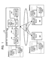
- Fig. 1 is a network block diagram depicting the concept of the present invention. This network is characterized in the configuration of the SONET/SDH transmission device 100 which inter-communicates by an inter-LAN connection.
- a plurality of LAN segments 1-N are connected to the SONET/SDH system using the SONET/SDH transmission device 100 as an interface.
- a SONET/SDH transmission device 100 has a LAN interface accommodation means 101 for accommodating a communication interface of the corresponding LAN 1-N.
- the traffic monitoring means 102 has a function to monitor the traffic of the LAN data which the local station (local node) transmits to another station (another node).
- the communication control means 103 matches the communication systems and controls communication for inter-connection between the LAN segment of the local station (local node) and the LAN segment of a station (another node) other than the local station.
- the path control means 104 controls the switching of the communication paths of the LAN data, which is transmitted by instructions from the traffic monitoring means 102, according to the traffic and communication path setting status.
- Fig. 3 shows a first embodiment to apply the present invention, indicating a SONET/SDH system with a ring configuration implementing a LAN accommodation by sharing bands.
- the SONET/SDH transmission device 12 which is respective node equipment constituting the SONET/SDH system, comprises a LAN interface 15 for accommodating a LAN segment 11 of the user, in addition to a conventional interface 14 for accommodating a line terminating device 13, which has a conventional communication interface.
- the SONET/SDH interface part 17 also has a monitoring control function part 18 having a function to monitor each node equipment, and a manager 19 which monitors and controls the SONET/SDH system by the DCC (Data Continuous Channel) information in the overhead of the data.
- DCC Data Continuous Channel
- UPSR Unidirectional Path Switched Ring
- BLSR Bi-directional Line Switched Ring
- Fig. 4 is a diagram depicting path setting and data routing during normal times in the SONET/SDH system with a ring configuration (UPSR system) in Fig. 3, where a conventional interface 14 between the node 01 (identification number of the SONET/SDH transmission device 12) and the node 04 is accommodated.
- UPSR system ring configuration
- a through path is set for the node 02 and the node 03, which are not connected, by the multiplexing/demultiplexing part 16.
- multiplexing/demultiplexing ADD/DROP
- receive data is selected so as to implement PP connection communication.
- the selector 161 in the multiplexing/demultiplexing part 16 is set so as to select a line at the side with a " ".
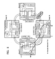
- Fig. 6 shows path setting between the LAN interface of each node to implement the band sharing system (mode) according to the present embodiment, and shows data routing between the node 01 and the node 04 during normal times as an example.
- This path setting can be applied to the UPSR/BLSR methods of the SONET/SDH system with a ring configuration.
- ADD/DROP is set for all the nodes, but receive data is not selected, and is directly connected to a packet switch part of the LAN interface 15, which will be described later (see Fig. 9, packet switch part 24).
- the packet switch part identifies data to be received by the local node and transfers the data which should not be received by the local node to the next node (through path). This data identification and transfer method will be described later.
- the traffic between the first node 01 and the last node 04 of the node identification number in the ring configuration is cutoff. In other words, the path is set but data does not flow.
- the node 04 and the node 03 can immediately recognize the failure X since it is a failure in the local node.
- the node 01 recognizes the occurrence of the failure and the location of the failure by receiving a failure notice in the monitoring control data flowing in the DCC (Data Continuous Channel) of the overhead (T0H) in the SONET/SDH frame at the ring side. Or manual operation control based on an instruction from the manager 19 is also possible.
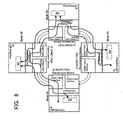
- Fig. 8 shows the case of a minimum band guarantee system (mode) where both a conventional PP connection path setting and a band sharing type path setting are used, and shows data routing between the node 01 and the node 04 as an example.
- mode a minimum band guarantee system
- a PP connection path is used for traffic in a fixed band between the node 01 and the node 04, and a band sharing path is used for overflow traffic, which is outside the fixed band in the PP connection when burst data is generated.
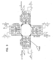
- Fig. 9 shows an example of the configuration of the LAN interface 15 to implement data transmission in the network configuration described as an embodiment in Fig. 3 and Fig. 6 to Fig. 8.
- the LAN interface 15 is comprised of a LAN interface part 21, a LAN data frame conversion part 22, a path selection part 23, a packet switch part 24, a traffic monitoring part 25, a local node operation condition setting part 27 and an address learning part 28.
- Frame conversion of LAN data in the frame conversion part 220 is a function to add a transmission destination node number DN (Destination Number), a transmission source node number SN (Source Number), which are the overhead data which make it possible to distribute packets by the packet switch 24 for each LAN data of the packet, and flags, to indicate the beginning and the end of the packet respectively.
- DN Denssion Number
- SN Transmission Source Node number
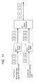
- Fig. 11 is a diagram depicting the configuration of a frame of the SONET/SDH system side packet (Fig. 11 (B)), which is converted from the LAN data (Fig. 11 (A)) by the frame conversion part 220.
- a DN value to indicate broadcast is added.
- Fig. 12 shows the general configuration of the path selection part 23 in Fig. 9 according to the embodiment. Operation of each operation mode depending on the path access mode in the SONET/SDH system will now be described.
- Fig. 13 is a diagram depicting the detailed configuration of the transmission part 230 in Fig. 12.
- the fixed switch 230-1 is set and fixed to the port (2) side by the operation condition setting part 27. Therefore, the packets from the LAN data frame conversion part 22 always flow into the port (2) side and are output from the port (B) 233.
- Fig. 14 is a diagram depicting the detailed configuration of the receiving part 231 in Fig. 12.
- the fixed switch 231-1 is set and fixed to the port (8) side by the operation condition setting part 27. Therefore, the received packets which were input from the port (B) 233 always flow into the port (8) side, and are output to the LAN data frame conversion part 22.
- burst data is generated in communication between nodes where the fixed band path is set in the minimum access band guarantee mode, and communication between LANs is generated exceeding the transfer capacity in the fixed band path, processing is executed as follows.
- the data is smoothed by the buffer part 221 of the LAN data frame conversion part 22 or the buffer 230-3 of the path selection part 23, and the data can be transferred to the transmission destination without losing data.
- the buffer part 222 and the buffer 230-3 cannot absorb all the data and data is lost due to a buffer overflow.
- the path to be used for a packet data transfer of the LAN in the SONET/SDH system is instantaneously changed before entering this overflow status. In this way, traffic exceeding the fixed band is shifted to the shared band, and data errors due to a loss of data can be minimized.
- the fixed switch 230-1 of the transmission part 230 of the path selection part 23 is set and fixed to the port (1) side by the operation condition setting port 27. By this, packets from the LAN data frame conversion part 22 always flow into the port (1) side, and are output to the filter switch 230-2.
- the filter switch 230-2 has been set such that the node number DN of the PP connection destination is "DNpp" by the operation condition setting part 27, and refers to the DN value of the SONET/SDH side packet in Fig. 11 and compares the DN value with the DNpp value. After this comparison, the packets are output to the port (3) side if the DN value is the same as "DNpp", or to the port (4) side if different.
- the packets When the packets are output to the port (4) side, the packets are output to the port (B) 233 as is. If the packets are output to the port (3) side, the packets are temporarily stored in the buffer 230-3 to monitor traffic or to relax an instantaneous congestion status, and then are output to the sequential path selection switch 230-4.
- the path selection switch 230-4 outputs the packets to the port (5) side (port (A) 232 at the fixed band path side) as long as the traffic does not exceed the fixed band path.
- the traffic monitoring part 25 recognizes a fixed band overflow, the traffic monitoring part 25 instructs switching so that the traffic which exceeded the fixed band is output to the port (6) side (port (B) 233 at the shared band path side).
- the path selection switch 230-4 adds a sequence number to indicate the sequence to the overhead of each packet before output. This processing will be described with reference to Fig. 15 and Fig. 16.
- Fig. 15 is a diagram depicting the processing to add the sequence number of the packet by the path selection switch 230-4, and Fig. 16 shows the frame configuration when the sequence number of the packet is added. The detailed operation to add the sequence number will be described below.
- the path selection function part 32 distributes the packet to either a fixed band path, which is set for inter-LAN connection, or a band sharing path.
- traffic within the fixed band is sent to the fixed band path side (port terminal (5)), and when a band overflow occurs by the generation of burst data, the traffic monitoring part 25, which monitors the traffic status, notifies of a band overflow (instructs to switch the path) and the path selection function part 32 transmits the packet to the band sharing path side (port terminal (6)).
- the distributed packet is sent to the packet switch part 24 which is connected to the port (A) 232 of the port terminal (5) side (fixed band path side) or to the port (B) 233 of the port terminal (6) side.
- a packet which is input from the shared band path (port (B) 233) side is also input to the packet combining part 231-2 in Fig. 14 since the fixed switch 231-1 is set and fixed to the port (7) side by the operation condition setting part 27.
- Fig. 17 shows a configuration example of the packet combining part 231-2. The detailed operation will now be described.
- the sequence number No attached to the header of the packet is referred to and the phase is matched in these receive buffers 33-1 and 33-2.
- the sequence number No added by the packet combining part 34 is removed from the packet, the packet sequence is corrected to normal, and the packets are sent to the LAN data frame conversion part 22.
- the following two types of detection functions are available as a method for the traffic monitoring part 25 to detect a band overflow due to burst error generation.
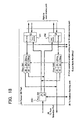
- Fig. 18 is a diagram depicting a configuration example of the packet switch part 24. Detailed operation of this configuration will now be described.
- a packet from the band sharing path is input to the filter switch SW1 or SW2 via the port C or port D respectively.
- the DN value of the packet and the DNmy value are compared by the filter switch SW1, and if both are "DNmy", then the packet flows into the port 20 side and is output to the path selection part 23 as a packet addressed to the local node.
- the packet flows into the port 21 side and is output from the port D to be transferred to the next node.
- the packet is output to both the ports 20 and 21 sides, and then is output to the port D to be received by the local node and to be transferred to the next node.
- the packet received from the port D is processed in the same way as the above packet received from the port C by the filter switch SW2.
- the packets received from the ports C and D are transferred in parallel to the address learning part 28 for address reference at transmission. This function will be described later.
- a packet from the path selection part 23 is input to the port switch part 240.
- the port switch part 240 refers to the learning table which the address learning part 28 has using the DA value of the packet, determines the port number No (C or D), then outputs the packet to the port 24 of the port switch part 240 if the packet is transferred to the node at the port C side. The packet is output to the port 25 if the packet is transferred to the port D side.
- Fig. 19 is a diagram depicting a configuration example of the address learning part 28 in Fig. 9. Detailed operation will now be described.
- the receive packet which is output from the packet switch part 24, is input to the address extraction parts 280 and 281 dedicated to the ports C and D.
- the address extraction parts 280 and 281 data associating the SN and SA values extracted from the receive packets with the input port number No (C or D) is generated.
- the time stamp which is periodically integrated and generated by the clock part 282 is added to the packet as a learning time, and the packet is output to the learning table part 283.
- the learning table part 283 generates a data table where the SA value in the above data is a label, and stores the data table. In the case of the same SA value, data is overwritten on the table with the same label, and the time stamp is updated.
- the table update part 284 constantly monitors the time stamp in the learning table 283 so as to effectively utilize the learning table 283 which has a limited number of tables, and if the time stamp is not updated for a specified time (e.g. 300 seconds) or longer, the table update part 284 deletes the table with the label. In other words, a table which is not used is deleted.
- a specified time e.g. 300 seconds
- Fig. 20 is a table indicating an example of the learning table values in the node 02 in Fig. 6.
- a plurality of virtual networks of LANs can be constructed in the same ring, the number of physically connected lines between LAN segments and communication cost can be dramatically reduced, and efficient inter-LAN communication utilizing bands in the SONET/SDH system become possible.
- the user can construct an economical system by an inter-LAN connection configuration using current LAN - WAN - LAN devices while considering expanding the LAN system in the future, and can decrease the management load by providing an interface which is common with the LAN managed by the user.
- a fixed band path of a PP connection is also created between specific nodes (LAN segments) in the above mentioned configuration
- the fixed band path which is normally used
- the shared band path which is used at a band overflow when burst data is generated, are dynamically switched depending on the traffic status, a minimum access band can be guaranteed between the nodes (LAN segments) where the fixed band path is also created, and the loss of data, which exceeded the fixed band due to a burst data generation, can be minimized during communication.
Landscapes
- Engineering & Computer Science (AREA)
- Computer Networks & Wireless Communication (AREA)
- Signal Processing (AREA)
- Data Exchanges In Wide-Area Networks (AREA)
- Small-Scale Networks (AREA)
Abstract
Description


Claims (17)
- An inter-LAN communication device for controlling inter-communication between a plurality of LAN segments connected in a ring configuration, comprising:LAN interface accommodation means for accommodating a communication interface of said LAN segments;traffic monitoring means for monitoring the traffic of LAN data;communication control means for controlling the communication for inter-connecting a LAN segment of a local node and a LAN segment of another node;path selection means for switching a communication path according to the instruction from the traffic monitoring means; andpacket switch control means for switching the packeted LAN data.
- The inter-LAN communication device according to Claim 1, wherein said communication control means further includes a buffer which stores data transmitted from the LAN segment, and said traffic monitoring means monitors traffic by monitoring the capacity of said buffer which stores data transmitted from the LAN segment.
- The inter-LAN communication device according to Claim 1, wherein said traffic monitoring means monitors traffic by monitoring the transmission intervals of data which are transmitted from the LAN segment.
- The inter-LAN communication device according to Claim 1, wherein said communication control means packets the LAN data by adding overhead which indicates the node numbers of a transmission source and a transmission destination.
- The inter-LAN communication device according to Claim 1, wherein said communication control means adds a sequence number for each packet at the transmission side so as to prevent a mismatch of the arrival sequence when the communication path is different for each packet due to path switching.
- The inter-LAN communication device according to Claim 5, wherein said path control means adds a sequence number for each packet after said added node number at the transmission side so as to prevent a mismatch of the arrival sequence when the communication path is different for each packet due to path switching.
- The inter-LAN communication device according to Claim 5, wherein said path control means matches the phases of packets by referring to said sequence numbers and deleting said sequence numbers of the added information at the receiving side.
- The inter-LAN communication device according to Claim 1, wherein said packet switch control means further includes an address learning part, which learns information where the transmission source and transmission detection node number information which is added to a packet sent from another LAN segment, the transmission source and transmission destination address information which the LAN data has, and the communication port information which the packet switch control means has, are associated and stores said association information.
- The inter-LAN communication device according to Claim 8, wherein for the node numbers of the overhead to indicate the transmission source and the transmission destination in said communication control means, a local node number which is preset, is added as the transmission source node number and the node number which is derived by searching and referring to said learned and stored association information on the node numbers, communication ports and addresses based on the transmission destination addresses which the LAN data bus has, is added as the transmission destination node number.
- The inter-LAN communication device according to Claim 8, wherein said packet switch control means compares the local number, which is preset, and the transmission destination node number of a packet sent from another node, which is another LAN segment, based on said learned and stored association information of the node numbers, ports and addresses, and the transmission destination packet is received by the local node if the transmission destination node number is the same as the local node number, and a communication port is selected and the packet is transferred if the transmission destination node number is another node number.
- An inter-LAN communication system where communication is performed connecting a plurality of LAN segments, comprising:said inter-LAN communication device further comprises:a network,an inter-LAN communication device which is installed at each one of a plurality of nodes of said network, anda LAN segment connected to said inter-LAN communication device, whereinan interface which is common with the LAN segment to be connected,means of monitoring traffic status of LAN data from said LAN segment,an address learning part which learns and stores data generated in one LAN segment based on said traffic status and routing information added to the LAN data from another LAN segment when the data is transferred to the other LAN segment, andpacket switch control means for inter-connecting one LAN segment and the other LAN segment based on said learned and stored information.
- The inter-LAN communication system according to Claim 11, wherein said packet switch control means in the inter-LAN communication device installed in each one of the plurality of nodes of said network further comprises two communication ports, and band sharing type inter-communication between the plurality of LAN segments is implemented by the cascade connection of the band (path) in a ring format.
- The inter-LAN communication system according to Claim 12, wherein said packet switch control means sets a fixed band path of a Point-to-Point connection between specified nodes, so as to guarantee a minimum access band between said nodes, and the band sharing path is used as a bypass route when traffic exceeds the band of said fixed band.
- The inter-LAN communication system according to Claim 12, wherein said packet switch control means always transmits the packeted LAN data for transmission to the band sharing path when only the band sharing type path is used.
- The inter-LAN communication system according to Claim 12, wherein said network is a SONET/SDH system used for each band (path), and has a plurality of ring configurations.
- The inter-LAN communication system according to Claim 13, wherein said path control means normally sends the packeted LAN data for transmission to said fixed band path when the minimum access band guarantee type is used, and dynamically switches traffic to the band sharing path when said means of monitoring traffic notifies a band overflow of said fixed band path.
- An inter-LAN communication system which performs inter-communication between a plurality of LAN segments connected in a ring configuration, comprising:said inter-LAN communication device further comprises:a network,an inter-LAN communication device which is installed in each one of the plurality of nodes of said network, anda LAN segment which is connected to said inter-LAN communication device, whereinLAN interface accommodating means for accommodating a communication interface of said LAN segment,traffic monitoring means for monitoring traffic of LAN data,communication control means for controlling communication to inter-connect the LAN segment of the local node and the LAN segment of another node,path selection means for switching a communication path according to instructions from the traffic monitoring means, andpacket switch control means for switching said packeted LAN data.
Applications Claiming Priority (2)
| Application Number | Priority Date | Filing Date | Title |
|---|---|---|---|
| JP2000089328A JP2001285322A (en) | 2000-03-28 | 2000-03-28 | Inter-LAN communication device and inter-LAN communication network using the same |
| JP2000089328 | 2000-03-28 |
Publications (2)
| Publication Number | Publication Date |
|---|---|
| EP1139612A2 true EP1139612A2 (en) | 2001-10-04 |
| EP1139612A3 EP1139612A3 (en) | 2003-07-09 |
Family
ID=18605099
Family Applications (1)
| Application Number | Title | Priority Date | Filing Date |
|---|---|---|---|
| EP01103600A Withdrawn EP1139612A3 (en) | 2000-03-28 | 2001-02-21 | Inter-LAN communication device and inter-LAN communication network employing the same |
Country Status (3)
| Country | Link |
|---|---|
| US (1) | US20010029546A1 (en) |
| EP (1) | EP1139612A3 (en) |
| JP (1) | JP2001285322A (en) |
Cited By (2)
| Publication number | Priority date | Publication date | Assignee | Title |
|---|---|---|---|---|
| WO2005029781A1 (en) * | 2003-09-11 | 2005-03-31 | Siemens Aktiengesellschaft | Method for handling data messages in a communications system, an appropriate communications system and subscribers thereof |
| US9439102B2 (en) | 2011-01-19 | 2016-09-06 | Fujitsu Limited | Transmitting apparatus, transmission method, and transmission system |
Families Citing this family (10)
| Publication number | Priority date | Publication date | Assignee | Title |
|---|---|---|---|---|
| US7068663B1 (en) * | 2001-01-23 | 2006-06-27 | Cisco Technology, Inc. | Path routing and provisioning method and apparatus |
| JP2002368774A (en) * | 2001-06-04 | 2002-12-20 | Fujitsu Ltd | Communication apparatus and method for setting line capacity thereof |
| US7031311B2 (en) * | 2001-07-23 | 2006-04-18 | Acme Packet, Inc. | System and method for providing rapid rerouting of real-time multi-media flows |
| WO2004105276A1 (en) * | 2003-05-19 | 2004-12-02 | Fujitsu Limited | Sdh transmission device and signal transmission method |
| JP4586379B2 (en) * | 2004-02-24 | 2010-11-24 | 日本電気株式会社 | Wireless transmission apparatus and method |
| JP2008167315A (en) * | 2006-12-28 | 2008-07-17 | Fujitsu Ltd | Redundant line connection method and wide area network node device |
| JP4762161B2 (en) * | 2007-01-19 | 2011-08-31 | 富士通株式会社 | Network device, network redundant connection method, and network redundant connection program |
| US8284654B2 (en) * | 2007-12-03 | 2012-10-09 | Verizon Patent And Licensing Inc. | Bandwidth admission control on link aggregation groups |
| JP5519387B2 (en) * | 2010-04-22 | 2014-06-11 | 富士通株式会社 | Transmission apparatus, transmission program, and transmission method |
| WO2013145150A1 (en) * | 2012-03-28 | 2013-10-03 | 富士通株式会社 | Communication device, communication method, and communication program |
Family Cites Families (17)
| Publication number | Priority date | Publication date | Assignee | Title |
|---|---|---|---|---|
| US4630261A (en) * | 1984-07-30 | 1986-12-16 | International Business Machines Corp. | Integrated buffer management and signaling technique |
| US5103447A (en) * | 1988-09-02 | 1992-04-07 | Hitachi, Ltd. | High-speed ring LAN system |
| US5060228A (en) * | 1988-11-19 | 1991-10-22 | Fujitsu Limited | Bridge communication system |
| US5809012A (en) * | 1991-01-31 | 1998-09-15 | Fujitsu Limited | Connectionless communication system |
| US5742760A (en) * | 1992-05-12 | 1998-04-21 | Compaq Computer Corporation | Network packet switch using shared memory for repeating and bridging packets at media rate |
| US5337313A (en) * | 1992-11-12 | 1994-08-09 | Motorola, Inc. | Method and apparatus for preserving packet squencing in a packet transmission system |
| JPH0795231A (en) * | 1993-07-29 | 1995-04-07 | Toshiba Corp | LAN connection device |
| US5412652A (en) * | 1993-09-24 | 1995-05-02 | Nec America, Inc. | Sonet ring subnetwork management method |
| AUPN573795A0 (en) * | 1995-10-02 | 1995-10-26 | Telefonaktiebolaget Lm Ericsson (Publ) | Transmitting data between multiple computer processors |
| US6222848B1 (en) * | 1997-12-22 | 2001-04-24 | Nortel Networks Limited | Gigabit ethernet interface to synchronous optical network (SONET) ring |
| US6404735B1 (en) * | 1998-04-30 | 2002-06-11 | Nortel Networks Limited | Methods and apparatus for distributed control of a multi-class network |
| US6584118B1 (en) * | 1998-08-27 | 2003-06-24 | Nortel Networks Limited | Payload mapping in synchronous networks |
| US6496519B1 (en) * | 1998-08-27 | 2002-12-17 | Nortel Networks Limited | Frame based data transmission over synchronous digital hierarchy network |
| US6724757B1 (en) * | 1999-01-15 | 2004-04-20 | Cisco Technology, Inc. | Configurable network router |
| GB2352105B (en) * | 1999-07-15 | 2001-09-26 | Marconi Comm Ltd | Optical system |
| US6697373B1 (en) * | 2000-01-18 | 2004-02-24 | Mark Henrik Sandstrom | Automatic method for dynamically matching the capacities of connections in a SDH/SONET network combined with fair sharing of network resources |
| US6973084B1 (en) * | 2000-02-23 | 2005-12-06 | Cypress Semiconductor Corp. | Hybrid data transport scheme over optical networks |
-
2000
- 2000-03-28 JP JP2000089328A patent/JP2001285322A/en active Pending
-
2001
- 2001-01-16 US US09/760,586 patent/US20010029546A1/en not_active Abandoned
- 2001-02-21 EP EP01103600A patent/EP1139612A3/en not_active Withdrawn
Cited By (2)
| Publication number | Priority date | Publication date | Assignee | Title |
|---|---|---|---|---|
| WO2005029781A1 (en) * | 2003-09-11 | 2005-03-31 | Siemens Aktiengesellschaft | Method for handling data messages in a communications system, an appropriate communications system and subscribers thereof |
| US9439102B2 (en) | 2011-01-19 | 2016-09-06 | Fujitsu Limited | Transmitting apparatus, transmission method, and transmission system |
Also Published As
| Publication number | Publication date |
|---|---|
| US20010029546A1 (en) | 2001-10-11 |
| EP1139612A3 (en) | 2003-07-09 |
| JP2001285322A (en) | 2001-10-12 |
Similar Documents
| Publication | Publication Date | Title |
|---|---|---|
| US6952395B1 (en) | Optical network restoration | |
| JP3371948B2 (en) | Information communication method and node for SONET circuit switching ring | |
| US20040208554A1 (en) | Packet/TDM integrated node apparatus | |
| US6301254B1 (en) | Virtual path ring protection method and apparatus | |
| EP1183835B1 (en) | Architecture for a hybrid stm/atm add-drop multiplexer | |
| US6975589B2 (en) | Method and apparatus for a hybrid variable rate pipe | |
| US6317439B1 (en) | Architecture for a SONET line unit including optical transceiver, cross-connect and synchronization subsystem | |
| US6647428B1 (en) | Architecture for transport of multiple services in connectionless packet-based communication networks | |
| US6532088B1 (en) | System and method for packet level distributed routing in fiber optic rings | |
| US6697373B1 (en) | Automatic method for dynamically matching the capacities of connections in a SDH/SONET network combined with fair sharing of network resources | |
| US7170852B1 (en) | Mesh with projection channel access (MPCA) | |
| US6940808B1 (en) | Adaptive rate traffic recovery mechanism for communication networks | |
| US20050122899A1 (en) | Apparatus and method for optical communication protection | |
| JP3624886B2 (en) | System and method for packet delivery in a ring network | |
| JP2000269999A (en) | Communication device between networks | |
| US7209436B1 (en) | Method and apparatus for variable rate pipes | |
| US7606224B2 (en) | Transmission apparatus for making ring switching at SONET/SDH and RPR levels | |
| US7016300B2 (en) | Protection mechanism for an optical ring | |
| WO2002098086A1 (en) | Hybrid time division multiplexing and data transport | |
| EP1139612A2 (en) | Inter-LAN communication device and inter-LAN communication network employing the same | |
| US6473397B1 (en) | Add/drop multiplexer and method, and Bi-directional line switcher ring featuring such multiplexers | |
| JPH10224390A (en) | Signal switching method | |
| US20020065073A1 (en) | Extended-cell communication network and transmission apparatus | |
| US7773612B2 (en) | Networking controller, device and communication network system of asynchronous transfer mode | |
| JP3151768B2 (en) | Self-healing ring system for synchronous and asynchronous transfer modes |
Legal Events
| Date | Code | Title | Description |
|---|---|---|---|
| PUAI | Public reference made under article 153(3) epc to a published international application that has entered the european phase |
Free format text: ORIGINAL CODE: 0009012 |
|
| 17P | Request for examination filed |
Effective date: 20010221 |
|
| AK | Designated contracting states |
Kind code of ref document: A2 Designated state(s): AT BE CH CY DE DK ES FI FR GB GR IE IT LI LU MC NL PT SE TR |
|
| AX | Request for extension of the european patent |
Free format text: AL;LT;LV;MK;RO;SI |
|
| PUAL | Search report despatched |
Free format text: ORIGINAL CODE: 0009013 |
|
| AK | Designated contracting states |
Designated state(s): AT BE CH CY DE DK ES FI FR GB GR IE IT LI LU MC NL PT SE TR |
|
| AX | Request for extension of the european patent |
Extension state: AL LT LV MK RO SI |
|
| AKX | Designation fees paid |
Designated state(s): DE FR GB |
|
| STAA | Information on the status of an ep patent application or granted ep patent |
Free format text: STATUS: THE APPLICATION HAS BEEN WITHDRAWN |
|
| 18W | Application withdrawn |
Effective date: 20070129 |