EP1139564A2 - Broadcast receiver comprising a means for scanning alternative frequencies without deteriorating the reception of a currently received broadcast programme - Google Patents
Broadcast receiver comprising a means for scanning alternative frequencies without deteriorating the reception of a currently received broadcast programme Download PDFInfo
- Publication number
- EP1139564A2 EP1139564A2 EP01107480A EP01107480A EP1139564A2 EP 1139564 A2 EP1139564 A2 EP 1139564A2 EP 01107480 A EP01107480 A EP 01107480A EP 01107480 A EP01107480 A EP 01107480A EP 1139564 A2 EP1139564 A2 EP 1139564A2
- Authority
- EP
- European Patent Office
- Prior art keywords
- station
- broadcast
- signal
- stations
- radio waves
- Prior art date
- Legal status (The legal status is an assumption and is not a legal conclusion. Google has not performed a legal analysis and makes no representation as to the accuracy of the status listed.)
- Withdrawn
Links
Images




Classifications
-
- H—ELECTRICITY
- H04—ELECTRIC COMMUNICATION TECHNIQUE
- H04H—BROADCAST COMMUNICATION
- H04H40/00—Arrangements specially adapted for receiving broadcast information
- H04H40/18—Arrangements characterised by circuits or components specially adapted for receiving
-
- H—ELECTRICITY
- H03—ELECTRONIC CIRCUITRY
- H03J—TUNING RESONANT CIRCUITS; SELECTING RESONANT CIRCUITS
- H03J1/00—Details of adjusting, driving, indicating, or mechanical control arrangements for resonant circuits in general
- H03J1/0008—Details of adjusting, driving, indicating, or mechanical control arrangements for resonant circuits in general using a central processing unit, e.g. a microprocessor
- H03J1/0058—Details of adjusting, driving, indicating, or mechanical control arrangements for resonant circuits in general using a central processing unit, e.g. a microprocessor provided with channel identification means
- H03J1/0066—Details of adjusting, driving, indicating, or mechanical control arrangements for resonant circuits in general using a central processing unit, e.g. a microprocessor provided with channel identification means with means for analysing the received signal strength
-
- H—ELECTRICITY
- H03—ELECTRONIC CIRCUITRY
- H03J—TUNING RESONANT CIRCUITS; SELECTING RESONANT CIRCUITS
- H03J1/00—Details of adjusting, driving, indicating, or mechanical control arrangements for resonant circuits in general
- H03J1/0008—Details of adjusting, driving, indicating, or mechanical control arrangements for resonant circuits in general using a central processing unit, e.g. a microprocessor
- H03J1/0091—Details of adjusting, driving, indicating, or mechanical control arrangements for resonant circuits in general using a central processing unit, e.g. a microprocessor provided with means for scanning over a band of frequencies
-
- H—ELECTRICITY
- H04—ELECTRIC COMMUNICATION TECHNIQUE
- H04H—BROADCAST COMMUNICATION
- H04H2201/00—Aspects of broadcast communication
- H04H2201/10—Aspects of broadcast communication characterised by the type of broadcast system
- H04H2201/20—Aspects of broadcast communication characterised by the type of broadcast system digital audio broadcasting [DAB]
Definitions
- the present invention relates to a receiver for broadcast radio waves.
- a broadcast receiver comprises: a station selecting part for selecting a broadcast station specified by a station selection command; a detection and demodulation part for receiving a radio wave from the broadcast station, and detecting and demodulating the same to generate a received signal; a signal analyzing part for analyzing the received signal and determining the signal processing mode; station selection control part for generating the station selection command using the result from the signal analyzing part; and reception status detecting part for interrupting, while receiving one broadcast station, the reception of the broadcast station and receiving other broadcast stations based on the station selection command, thereby detecting the reception status of radio waves from the other stations.
- Fig. 1 is a block diagram showing the configuration of an ISDB-T (Terrestrial Integrated Services Digital Broadcasting) receiver according to the present invention.
- ISDB-T Transrestrial Integrated Services Digital Broadcasting
- a receiving antenna 10 is a small-size antenna such as a rod antenna and a planar antenna.
- the receiving antenna 10 receives radio waves from broadcast stations.
- An RF part 11 governs the front end functions of the receiver, including high frequency amplification and frequency conversion on the radio waves received by the receiving antenna 10.
- a station selection and tuning part 12 has the function of tuning and selecting, under a station selection command signal from a system control part 20, the radio wave from a specific broadcast station out of the received radio waves based on a predetermined station selection pattern and timing.
- a detection and demodulation part 13 consists chiefly of an OFDM demodulation circuit to be described later.
- the detection and demodulation part 13 detects and demodulates received radio waves supplied from the station selection and tuning part 12 to generate received data, which is supplied to an output signal processing part and other processing circuits.
- a received radio wave detection part 14 applies AM detection to the output of the station selection and tuning part 12, thereby detecting whether or not a carrier exists on a desired frequency. The result is supplied to the system control part 20.
- a received radio wave attribute decision part 15 distinguishes whether the received radio waves mentioned above are ISDB-T broadcast radio waves or analog broadcast radio waves. The result is supplied to the system control part 20.
- a received signal error rate detection part 18 checks the demodulation data error rate of a received ISDB-T broadcast signal. The result is supplied to the system control part 20.
- a TMCC signal detection part 17 detects a transmission and multiplexing configuration control (TMCC) signal, a kind of control signal included in ISDB-T broadcast data, and supplies the same to the system control part 20.
- TMCC transmission and multiplexing configuration control
- a guard interval detection part 16 detects guard intervals included in the received ISDB-T broadcast signal, and supplies the same to the system control part 20.
- An output signal processing part 19 reproduces the picture signals and sound signals transmitted from broadcast stations, based on the demodulation data supplied from the detection and demodulation part 13.
- the reproduced signals are output to display equipment such as a CRT and a liquid crystal panel, and/or audio equipment such as loudspeakers and headphones.
- An operation input part 22 comprises a keyboard or a group of switches from which a variety of operation commands such as a station selection command are input to this receiver.
- the system control part 20 consisting chiefly of a microcomputer, controls the operations of the entire receiver.
- the system control part 20 executes a main routine stored in a memory part 21 step by step in synchronization with an internal clock.
- the memory part 21 is composed of memory elements including a read only memory (ROM) and a random access memory (RAM).
- ROM read only memory
- RAM random access memory
- the ROM stores programs pertaining to the main routine for controlling the operations of this receiver as well as various subroutines.
- the RAM temporarily stores the results of the processing by the main routine and various subroutines.
- the system control part 20 executes a processing subroutine for the other-station radio wave detecting mode shown in Fig. 2.
- This subroutine is executed, for example, at predetermined intervals by interrupting the main routine (description omitted) that is to be run full-time in synchronization with the internal clock.
- the system control part 20 in accordance with the step 10 of the above-mentioned subroutine, detects whether the received signal error rate of the currently-receiving ISDB-T broadcast radio wave is lower than or equal to a predetermined value.
- Such an operation is associated not only with the software processing but also with the operations of the hardware device, or the receiver' s individual parts, including reception of broadcast radio waves to demodulation of received data. The following provides a brief explanation thereof.
- ISDB-T broadcast radio waves from broadcast stations are received at the antenna 10.
- these radio waves are amplified and subjected to frequency conversion and/or other front end processing for high frequency signals, and then supplied to the station selection and tuning part 12.
- the station selection and tuning part 12 in accordance with the station select command signal from the system control part 20, tunes and selects only the radio wave from a desired broadcast station out of the received radio waves.
- the resulting received radio wave is supplied to the detection and demodulation part 13.
- ISDB-T broadcast radio waves are OFDM (Orthogonal Frequency Division Multiplex) modulated.
- the detection and demodulation part 13 provides two local oscillating carriers 13a and 13b having a 90 degree phase difference therebetween.
- the output signal from the station selection and tuning part 12 is multiplied by these carriers, so as to extract the orthogonal component and in-phase component included in that signal.
- the detection and demodulation part 13 converts these components into digital values in its analog/digital converter 13c.
- An AFC (Automatic Frequency Control) circuit 13d brings the values into frequency synchronization for OFDM demodulation, and a fast Fourier transformer 13e applies Fourier transformation thereto, whereby digital data included in the respective carriers is demodulated.
- the demodulated data is temporarily stored into an output buffer 13f, and subjected to such processing as deinterleaving and error correction to be described later. Then, the data is output to the output signal processing part 19 and other processing circuits at predetermined timing.
- the received signal error rate detection part 18 checks the error rate of the received signal.
- send data is transmitted with error-correcting codes such as Reed-Solomon codes and convolution codes for the sake of high quality data transmission.
- error-correcting codes such as Reed-Solomon codes and convolution codes for the sake of high quality data transmission.
- the signal error rate of the received data sometimes increases due to deterioration of radio wave propagation environment.
- the system control part 20 determines, at the step 10, that the result of the detection by the error rate detection part 18 exceeds a predetermined value, it terminates the subroutine shown in Fig. 2 without performing the detection of radio waves of other-stations.
- the reason for this is that interrupting the currently-receiving radio wave to perform the other-station detection in such a condition causes a received data loss, contributing a further increase in the error rate.
- the determination processing at the step 10 means that the other-station radio wave detection is not particularly conducted when the currently-receiving broadcast station has a poor reception status.
- the system control part 20 supplies the station selection and tuning part 12 with a station selection command signal for maintaining the tuning to the currently selected, received station.
- the system control part 20 obtains the TMCC signal included in the demodulated data through the TMCC signal detection part 17, and analyzes the same (step 11).
- the TMCC signal is a kind of control signal included in ISDB-T broadcast data, and comprises parameter information that defines the modulation scheme of the ISDB-T broadcast radio waves as well as various attributes pertaining to digital data to be transmitted.
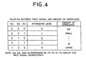
- a TMCC signal is 204-bit long, in which 3 bits in a group, or the maximum of 9 bits depending on the number of layers, are used as an identifier for indicating the amount of interleave of transmission data along the current time axis.
- Sending data in ISDB-T broadcasting involves the addition of the error-correcting codes as described before. Therefore, received data can be error-corrected at the reception side even if dropouts of relatively short data, or random errors, occur during the data transmission. However, when losses of relatively long data, or burst errors, occur and the number of bits of the error-lost data exceeds the redundancy of the error-correcting codes, the error correction of data at the reception side becomes difficult.
- interleave time-based interleave processing
- the application of the time-based interleave processing can convert the data losses resulting from burst errors into random errors capable of being error-corrected.
- the identifier in the TMCC signal indicating the amount of interleave is a parameter for showing the degree of application of such interleave.
- the table of Fig. 4 shows the definition thereof.
- the interleave level 0 represents the state where no interleave is applied to transmission data.
- the amount of interleave applied to transmission data increases with ascending levels.
- the amount of interleave depends on such parameters as the signal modulation scheme and the data attributes.
- the signal modulation scheme and the data attributes.
- the signal correction capability becomes greater with respect to the interruption of the received signal. From a different point of view, this means that received signals with greater amounts of interleave can be interrupted for longer time.
- the system control part 20 checks the 35-th to 37-th bits of the TMCC signal (hereinafter, these three bits will be exclusively referred to as a TMCC signal) obtained from the TMCC signal detection part. If the value is "000,” the system control part 20 terminates the subroutine of Fig. 2 without performing the other-station radio wave detection processing.
- the TMCC signal is "000," the currently-receiving ISDB-T broadcast data is not interleaved. Therefore, if the reception of such data is interrupted to perform the other-station radio wave detection, the deinterleave processing cannot convert the loss of data resulting from the interrupted reception into random errors, possibly failing to correct/recover the received data.
- the system control part 20 determines whether the TMCC signal is "001" or "010.” If the TMCC signal is "001" or "010,” then the system control part 20 starts the processing of detecting the received radio wave from other stations (step 13).
- the currently-receiving digital data is interleaved at relatively lower level 1 or level 2 shown in the table of Fig. 4. Therefore, if for a relatively short period of time, the reception can be interrupted to detect other-station radio waves while the deinterleave processing in the detection and demodulation part 13 can convert the data loss resulting from the interruption of reception into random errors.
- the system control part 20 generates station select command signals in accordance with a predetermined station selecting procedure and station selecting timing.
- the system control part 20 supplies the signals to the station selection and tuning part 12, thereby successively changing the tuning frequency so as to select broad stations other than the currently-receiving one.
- a variety of patterns are conceivable for such a station selecting procedure. Possible examples include a method in which the tuning frequency is swept across the receivable frequency band of the present receiver, and a method in which the frequencies of broadcast stations having been preset by the user from the operation input part 22 are successively picked up for scan.
- a variety of patterns are also conceivable for the station selecting timing.
- the pattern of the first example is the case where the interruptions of the currently-receiving station are made as short as possible.
- burst errors resulting from the interruptions can be reduced to a minimum, whereas it takes time to detect the reception status of all the other stations.
- the pattern of the second example is the case of adopting the maximum interruption time which causes no hitches in demodulating the data from the currently-receiving station.
- the second example has a higher probability of occurrence of burst errors due to noises and other disturbances. However, it allows a significant reduction of time required for detecting all the other stations.
- the detection of the other-station reception status at the step 13 is limited to the detection of the presence/absence of radio waves of other-stations. This is because the smaller amount of interleave allows only short interruption time to be set.
- radio waves can be received at the other-station frequencies tuned and selected by the station selection and tuning part 12, is detectable by the received radio wave detection part 14 applying AM detection to the output signal of the station selection and tuning part 12.
- the received radio wave detection part 14 supplies the result to the system control part 20.
- the system control part 20 stores the success or failure of the reception of the radio waves from the selected stations, as well as channel information of those other stations, into a storage area (hereinafter, referred to as memory table) on the RAM of the memory part 21. If all the other stations that are predetermined to be detected are scanned for, the system control part 20 terminates this subroutine (step 14).
- the system control part 20, at the next step 15, determines whether the TMCC signal is "011" or "100.”
- the currently-receiving digital data is interleaved at relatively higher level 3 or level 4 shown in the table of Fig. 4.
- the radio waves from the currently-receiving broadcast station can be interrupted more than in the processing at the above-described step 13 while the deinterleave processing in the detection and demodulation part 13 can convert the data losses resulting from the interruption of reception into random errors.
- the system control part 20 if the TMCC signal is "011" or "100,” performs not only the detection of the received radio waves from other stations but also makes determinations that require more processing time. Specifically, the system control part 20 determines the attributes of the radio waves from the detected stations, i.e., whether the detected stations are analog stations or digital stations.
- the system control part 20 makes operations as in a third example shown in Fig. 7. That is, at the steps 16 and 17, the system control part 20 performs the same other-station radio waves detection processing as in the steps 13 and 14, so that the reception status of the radio waves from the other stations is temporarily stored into the memory table on the RAM area mentioned above.
- the system control part 20 searches the above-mentioned memory table, extracts only the other stations whose radio waves can be received, and supplies the station selection and tuning part 12 with station selection command signals for selecting those stations (step 18).
- the radio waves selected by the station selection and tuning part 12 based on such station selection commands are supplied to the received radio wave attribute decision part 15, whereby the attribute of the radio waves, or whether the selected radio waves are of ISDB-T broadcasting or of analog broadcasting, is decided.
- the received radio wave attribute decision part 15 measures the output signal of the station selection and tuning part 12 for signal levels on a plurality of frequency points. The attribute decision part 15 then identifies whether radio waves selected are of analog broadcasting or ISDB-T broadcasting, based on the ratios of levels among the individual points. The result is supplied to the system control part 20.
- the result from the attribute decision part 15 may also be used as long as their combination enhances the reliability of the received radio wave attribute decision. More specifically, when analog broadcast radio waves are detected and demodulated by the detection and demodulation part 13, it naturally follows that the TMCC signal, a control signal added in ISDB-T broadcasting, cannot be detected. Accordingly, the difference in frequency spectrum described before and the presence/absence of the TMCC signal detection are combined to decide the attributes of the received radio waves.
- the determination of attribute of received radio waves i.e., the detection as to whether the received radio waves are analog radio waves or digital radio waves is based on the difference in frequency spectrum and/or the presence/absence of the TMCC signal as described above.
- the present invention is not limited thereto.
- the presence/absence of guard intervals to be described later, the detection of their timing, and all may be used as long as they utilize a difference in broadcasting mode.
- the system control part 20 selects receivable stations stored in the above-mentioned memory table on a one-by-one basis, and decides the attributes of the received radio waves of those stations based on the method described above.
- the results are stored into the memory table as the attributes of receivable other-station radio waves, along with channel information.
- the system control part 20 if having determined the radio wave attributes of all the receivable stations stored in the memory table, terminates this subroutine (step 19).
- the system control part 20 terminates this subroutine with the currently-receiving station maintained as selected.
- ISDB-T broadcast radio waves are provided with guard intervals during data transmission.
- a guard interval is an effective symbol in transmission data, cut away in 1/4- to 1/32-long at the tail and inserted into the interval from the preceding effective symbol. While the provision of such guard intervals lowers the data transmission efficiency, the guard interval periods can prevent delay interference resulting from reflected radio waves such as multipath radio waves. Accordingly, it becomes possible to prevent ghosts which are the biggest trouble to broadcast radio waves.
- the effective symbols without the guard intervals can be exclusively demodulated to reproduce the transmission data. Therefore, during demodulation, windows extending along the time axis, covering effective symbols alone are established so that fast Fourier transformation is exclusively applied to the received signals in such windows. That is, even if guard intervals have data losses, the data demodulation suffers no influences therefrom.
- a modified embodiment of the present invention may include the processing of performing the other-station detecting operations by utilizing such guard interval periods.
- the guard interval detection part 16 detects whether or not guard intervals are provided for the currently-receiving ISDB-T broadcast data. If guard intervals are provided, the guard interval detection part 16 notifies the system control part 20 of it. Recognizing such a circumstance, the system control part 20, in detecting other-station radio waves (steps 13 and 16) or determining the attributes of other-station radio waves (step 18) in the flowchart shown in Fig. 2, exclusively uses guard interval periods or preferentially uses the guard interval periods to take steps for performing the detecting or determining operation.
- the present invention is not limited to ISDB-T broadcasts, and is applicable to any broadcast as long as the transmission data is interleaved along the time axis.
- determinations have been exclusively made as to the presence/absence of radio waves from broadcast stations and as to whether the stations are analog stations or digital stations.
- the determination may also include a variety of information such as the name of the program being broadcast, the program contents, and the genre.
- the detection conditions are not limited thereto. What is essential is only that a broadcast reception status with no hitches to the demodulation of received data can be secured even if the other-station detection causes burst errors to the currently-receiving station signal.
- such parameters as the transmission mode of the broadcast, the amount of guard intervals, and the method of modulation may be used as the detection conditions to make an other-station detecting operation as described in the embodiment.
- these conditions and the time-based interleave may be put together into practice.
- the present embodiment has been described with the ISDB-T broadcast receiver as an example. However, the present invention is not limited thereto, and is applicable to any digital broadcast receiver which transmits information in consecutive time series data. Besides, the present embodiment has used the TMCC signal to detect the time-based interleave, whereas the present invention is not limited thereto. Frame intervals or other identification signals may be used to detect the time-based interleave.
- a digital broadcast receiver which transmits information in consecutive time series data can detect the reception status of other stations, and recognize receivable broadcast stations in advance, without deteriorating the reception status of the currently-receiving station. This means an improvement in the operability and convenience upon station selections.
Landscapes
- Engineering & Computer Science (AREA)
- Signal Processing (AREA)
- Computer Hardware Design (AREA)
- Microelectronics & Electronic Packaging (AREA)
- Circuits Of Receivers In General (AREA)
Abstract
Description
Claims (5)
- A broadcast receiver comprising:a station selecting part for selecting a broadcast station specified by a station selection command;a detection and demodulation part for receiving a radio wave from said broadcast station, and detecting and demodulating said radio wave to generate a received signal;a signal analyzing part for analyzing said received signal and determining a signal processing mode;a station selection controlling part for generating said station selection command using the result from said signal analyzing part; anda reception status detecting part for interrupting, while receiving one broadcast station, the reception of said one broadcast station and receiving other broadcast stations based on said station selection command, thereby detecting a reception status of radio waves from the other stations.
- The broadcast receiver according to claim 1, wherein said signal analyzing part extracts a control signal from said received signal and analyzes the control signal, said control signal indicating whether or not said received signal is interleaved along the time axis.
- The broadcast receiver according to claim 2, wherein:said signal analyzing part detects the amount of interleave included in said control signal for analysis; andsaid station selection controlling part generates said station selection command in accordance with the result of the detection and analysis.
- The broadcast receiver according to claim 3, wherein said station selection controlling part evaluates the reception status of the currently-receiving radio wave, and generates said station selection command so as to include the result of the evaluation.
- The broadcast receiver according to claim 4, wherein said station selection controlling part generates, when the currently-receiving radio wave have a guard interval period in their signal, the station selection command for performing the reception of other broadcast stations during said period.
Applications Claiming Priority (2)
| Application Number | Priority Date | Filing Date | Title |
|---|---|---|---|
| JP2000097424 | 2000-03-31 | ||
| JP2000097424A JP3833868B2 (en) | 2000-03-31 | 2000-03-31 | Broadcast receiver |
Publications (2)
| Publication Number | Publication Date |
|---|---|
| EP1139564A2 true EP1139564A2 (en) | 2001-10-04 |
| EP1139564A3 EP1139564A3 (en) | 2005-06-08 |
Family
ID=18612046
Family Applications (1)
| Application Number | Title | Priority Date | Filing Date |
|---|---|---|---|
| EP01107480A Withdrawn EP1139564A3 (en) | 2000-03-31 | 2001-03-28 | Broadcast receiver comprising a means for scanning alternative frequencies without deteriorating the reception of a currently received broadcast programme |
Country Status (3)
| Country | Link |
|---|---|
| US (1) | US7184726B2 (en) |
| EP (1) | EP1139564A3 (en) |
| JP (1) | JP3833868B2 (en) |
Cited By (3)
| Publication number | Priority date | Publication date | Assignee | Title |
|---|---|---|---|---|
| FR2890808A1 (en) * | 2005-09-13 | 2007-03-16 | France Telecom | SPECTRUM CHARACTERIZATION FOR COMMUNICATION EQUIPMENT |
| EP1696575A4 (en) * | 2003-12-16 | 2008-02-13 | Matsushita Electric Industrial Co Ltd | RECEIVER DEVICE AND RECEPTION PROCEDURE |
| EP2858276A1 (en) * | 2013-10-01 | 2015-04-08 | Nxp B.V. | Receiver |
Families Citing this family (10)
| Publication number | Priority date | Publication date | Assignee | Title |
|---|---|---|---|---|
| JP3663126B2 (en) | 2000-12-04 | 2005-06-22 | 三洋電機株式会社 | Digital broadcast receiver |
| US20050143169A1 (en) * | 2001-09-20 | 2005-06-30 | Igt | Direction interfaces and services on a gaming machine |
| WO2006105010A1 (en) | 2005-03-25 | 2006-10-05 | Neocific, Inc. | Methods and apparatus for cellular broadcasting and communication system |
| US7793170B2 (en) * | 2004-05-13 | 2010-09-07 | Ittiam Systems (P) Ltd. | Method and apparatus for combining de-interleaving with FFT and demapping |
| US7400904B2 (en) * | 2004-12-03 | 2008-07-15 | Itron, Inc. | Dual mode AM-FM receiver with I-Q decoding, such as for utility data collection |
| JP4537876B2 (en) * | 2005-03-31 | 2010-09-08 | 株式会社東芝 | Gap filler device |
| CN101091390B (en) | 2005-06-09 | 2011-01-12 | 桥扬科技有限公司 | Method and apparatus for power efficient broadcast and communication system |
| KR101650749B1 (en) * | 2009-08-18 | 2016-08-24 | 삼성전자주식회사 | Method and apparatus for allocation and indication of control channel in backhaul subframe for relay |
| WO2012050838A1 (en) | 2010-09-28 | 2012-04-19 | Neocific, Inc. | Methods and apparatus for flexible use of frequency bands |
| US9467241B2 (en) * | 2014-01-06 | 2016-10-11 | Ford Global Technologies, Llc | Radio station genre categorization |
Family Cites Families (11)
| Publication number | Priority date | Publication date | Assignee | Title |
|---|---|---|---|---|
| FR2658375B2 (en) * | 1989-05-25 | 1994-04-22 | Adventure | ELECTRONIC DEVICE FOR ALLOWING INDIVIDUAL PARTICIPATION IN A BROADCASTING PROGRAM. |
| US5465396A (en) * | 1993-01-12 | 1995-11-07 | Usa Digital Radio Partners, L.P. | In-band on-channel digital broadcasting |
| JP3360705B2 (en) * | 1994-12-21 | 2002-12-24 | ソニー株式会社 | Broadcast receiving device and broadcast receiving method |
| JP2710591B2 (en) | 1995-08-16 | 1998-02-10 | 日本電気アイシーマイコンシステム株式会社 | Radio receiver |
| JPH1055656A (en) * | 1996-08-08 | 1998-02-24 | Sony Corp | Receiving information recording system |
| JP3929553B2 (en) * | 1997-06-11 | 2007-06-13 | 株式会社フィリップスエレクトロニクスジャパン | Reception control method for data broadcasting receiver |
| SE9703331D0 (en) * | 1997-09-16 | 1997-09-16 | Teracom Ab | Method and device for change of reception |
| US6259482B1 (en) * | 1998-03-11 | 2001-07-10 | Matthew F. Easley | Digital BTSC compander system |
| US6351290B1 (en) * | 1998-03-23 | 2002-02-26 | Samsung Electronics Co., Ltd. | Television receiver with separate I-F amplifiers for VSB and QAM digital TV signals that are digitally synchrodyned |
| JP4249821B2 (en) * | 1998-08-31 | 2009-04-08 | 富士通株式会社 | Digital audio playback device |
| US6154452A (en) * | 1999-05-26 | 2000-11-28 | Xm Satellite Radio Inc. | Method and apparatus for continuous cross-channel interleaving |
-
2000
- 2000-03-31 JP JP2000097424A patent/JP3833868B2/en not_active Expired - Fee Related
-
2001
- 2001-03-28 EP EP01107480A patent/EP1139564A3/en not_active Withdrawn
- 2001-04-02 US US09/822,835 patent/US7184726B2/en not_active Expired - Fee Related
Cited By (8)
| Publication number | Priority date | Publication date | Assignee | Title |
|---|---|---|---|---|
| EP1696575A4 (en) * | 2003-12-16 | 2008-02-13 | Matsushita Electric Industrial Co Ltd | RECEIVER DEVICE AND RECEPTION PROCEDURE |
| FR2890808A1 (en) * | 2005-09-13 | 2007-03-16 | France Telecom | SPECTRUM CHARACTERIZATION FOR COMMUNICATION EQUIPMENT |
| WO2007031646A1 (en) * | 2005-09-13 | 2007-03-22 | France Telecom | Spectrum characterization for communication equipment |
| US8098570B2 (en) | 2005-09-13 | 2012-01-17 | France Telecom | Spectrum characterization for communication equipment |
| CN101263698B (en) * | 2005-09-13 | 2012-07-18 | 法国电信公司 | Spectrum Characterization of Communication Devices |
| EP2858276A1 (en) * | 2013-10-01 | 2015-04-08 | Nxp B.V. | Receiver |
| CN104518849A (en) * | 2013-10-01 | 2015-04-15 | 恩智浦有限公司 | Receiver |
| US10333641B2 (en) | 2013-10-01 | 2019-06-25 | Nxp B.V. | Receiver |
Also Published As
| Publication number | Publication date |
|---|---|
| JP3833868B2 (en) | 2006-10-18 |
| US7184726B2 (en) | 2007-02-27 |
| JP2001285103A (en) | 2001-10-12 |
| EP1139564A3 (en) | 2005-06-08 |
| US20030045254A1 (en) | 2003-03-06 |
Similar Documents
| Publication | Publication Date | Title |
|---|---|---|
| US8422976B2 (en) | Antenna diversity system for relatively broadband broadcast reception in vehicles | |
| US7184726B2 (en) | Broadcast receiver | |
| JPH10313285A (en) | Digital audio broadcasting receiver | |
| US6731702B1 (en) | Null symbol position detecting method, null symbol position detecting apparatus, and receiver | |
| US20050123083A1 (en) | Receiver, receiving method, reception control program, and storage medium | |
| EP1148684A2 (en) | Antenna switching in a receiver for digital broadcasts | |
| EP1350317B1 (en) | Apparatus and method for optimizing the level of rf signals based upon the information stored on a memory | |
| US6437837B1 (en) | Digital broadcast signal processing apparatus and method in which channel interference by analog broadcast is prevented | |
| CA2661711A1 (en) | Broadcast receiver and broadcast channel seek method | |
| JPH0787556B2 (en) | TV receiver | |
| EP1643706A1 (en) | Digital broadcast receiving apparatus and receiving method | |
| EP2151925B1 (en) | Digital broadcast receiver | |
| JP2001103394A (en) | Digital broadcast receiver | |
| EP0944194A2 (en) | Receiver for the reception of digital broadcasts | |
| JP3809988B2 (en) | Receiver | |
| JP2001285156A (en) | Diversity receiver | |
| JP2004236076A (en) | Receiving device and receiving method | |
| EP0944213B1 (en) | Digital broadcast receiver | |
| JP4173171B2 (en) | Radio receiver and carrier wave detection method | |
| EP1162836A2 (en) | Television receiver for receiving both analog and digital broadcast programmes | |
| JP3841665B2 (en) | OFDM signal reception quality evaluation apparatus and its reception quality evaluation method | |
| EP1926306A1 (en) | Method and apparatus for automatic fine tuning based on sync detection | |
| WO2001006775A9 (en) | Method and apparatus for autoprogramming a television receiver | |
| KR100413410B1 (en) | Automatic setting of local oscillation frequency of low noise block of satellite broadcasting receiver | |
| JP4134920B2 (en) | OFDM signal receiving apparatus and OFDM signal receiving method |
Legal Events
| Date | Code | Title | Description |
|---|---|---|---|
| PUAI | Public reference made under article 153(3) epc to a published international application that has entered the european phase |
Free format text: ORIGINAL CODE: 0009012 |
|
| AK | Designated contracting states |
Kind code of ref document: A2 Designated state(s): AT BE CH CY DE DK ES FI FR GB GR IE IT LI LU MC NL PT SE TR |
|
| AX | Request for extension of the european patent |
Free format text: AL;LT;LV;MK;RO;SI |
|
| PUAL | Search report despatched |
Free format text: ORIGINAL CODE: 0009013 |
|
| AK | Designated contracting states |
Kind code of ref document: A3 Designated state(s): AT BE CH CY DE DK ES FI FR GB GR IE IT LI LU MC NL PT SE TR |
|
| AX | Request for extension of the european patent |
Extension state: AL LT LV MK RO SI |
|
| 17P | Request for examination filed |
Effective date: 20050608 |
|
| AKX | Designation fees paid |
Designated state(s): DE FR GB |
|
| STAA | Information on the status of an ep patent application or granted ep patent |
Free format text: STATUS: THE APPLICATION IS DEEMED TO BE WITHDRAWN |
|
| 18D | Application deemed to be withdrawn |
Effective date: 20081001 |