EP1139520A2 - Laser resonator - Google Patents
Laser resonator Download PDFInfo
- Publication number
- EP1139520A2 EP1139520A2 EP01106799A EP01106799A EP1139520A2 EP 1139520 A2 EP1139520 A2 EP 1139520A2 EP 01106799 A EP01106799 A EP 01106799A EP 01106799 A EP01106799 A EP 01106799A EP 1139520 A2 EP1139520 A2 EP 1139520A2
- Authority
- EP
- European Patent Office
- Prior art keywords
- laser
- telescope
- laser beam
- resonator
- reflecting means
- Prior art date
- Legal status (The legal status is an assumption and is not a legal conclusion. Google has not performed a legal analysis and makes no representation as to the accuracy of the status listed.)
- Granted
Links
Images






Classifications
-
- H—ELECTRICITY
- H01—ELECTRIC ELEMENTS
- H01S—DEVICES USING THE PROCESS OF LIGHT AMPLIFICATION BY STIMULATED EMISSION OF RADIATION [LASER] TO AMPLIFY OR GENERATE LIGHT; DEVICES USING STIMULATED EMISSION OF ELECTROMAGNETIC RADIATION IN WAVE RANGES OTHER THAN OPTICAL
- H01S3/00—Lasers, i.e. devices using stimulated emission of electromagnetic radiation in the infrared, visible or ultraviolet wave range
- H01S3/05—Construction or shape of optical resonators; Accommodation of active medium therein; Shape of active medium
- H01S3/08—Construction or shape of optical resonators or components thereof
- H01S3/08018—Mode suppression
- H01S3/0804—Transverse or lateral modes
- H01S3/08045—Single-mode emission
-
- H—ELECTRICITY
- H01—ELECTRIC ELEMENTS
- H01S—DEVICES USING THE PROCESS OF LIGHT AMPLIFICATION BY STIMULATED EMISSION OF RADIATION [LASER] TO AMPLIFY OR GENERATE LIGHT; DEVICES USING STIMULATED EMISSION OF ELECTROMAGNETIC RADIATION IN WAVE RANGES OTHER THAN OPTICAL
- H01S3/00—Lasers, i.e. devices using stimulated emission of electromagnetic radiation in the infrared, visible or ultraviolet wave range
- H01S3/05—Construction or shape of optical resonators; Accommodation of active medium therein; Shape of active medium
- H01S3/08—Construction or shape of optical resonators or components thereof
-
- H—ELECTRICITY
- H01—ELECTRIC ELEMENTS
- H01S—DEVICES USING THE PROCESS OF LIGHT AMPLIFICATION BY STIMULATED EMISSION OF RADIATION [LASER] TO AMPLIFY OR GENERATE LIGHT; DEVICES USING STIMULATED EMISSION OF ELECTROMAGNETIC RADIATION IN WAVE RANGES OTHER THAN OPTICAL
- H01S3/00—Lasers, i.e. devices using stimulated emission of electromagnetic radiation in the infrared, visible or ultraviolet wave range
- H01S3/05—Construction or shape of optical resonators; Accommodation of active medium therein; Shape of active medium
- H01S3/08—Construction or shape of optical resonators or components thereof
- H01S3/08018—Mode suppression
- H01S3/0804—Transverse or lateral modes
- H01S3/0805—Transverse or lateral modes by apertures, e.g. pin-holes or knife-edges
-
- H—ELECTRICITY
- H01—ELECTRIC ELEMENTS
- H01S—DEVICES USING THE PROCESS OF LIGHT AMPLIFICATION BY STIMULATED EMISSION OF RADIATION [LASER] TO AMPLIFY OR GENERATE LIGHT; DEVICES USING STIMULATED EMISSION OF ELECTROMAGNETIC RADIATION IN WAVE RANGES OTHER THAN OPTICAL
- H01S3/00—Lasers, i.e. devices using stimulated emission of electromagnetic radiation in the infrared, visible or ultraviolet wave range
- H01S3/05—Construction or shape of optical resonators; Accommodation of active medium therein; Shape of active medium
- H01S3/08—Construction or shape of optical resonators or components thereof
- H01S3/08059—Constructional details of the reflector, e.g. shape
-
- H—ELECTRICITY
- H01—ELECTRIC ELEMENTS
- H01S—DEVICES USING THE PROCESS OF LIGHT AMPLIFICATION BY STIMULATED EMISSION OF RADIATION [LASER] TO AMPLIFY OR GENERATE LIGHT; DEVICES USING STIMULATED EMISSION OF ELECTROMAGNETIC RADIATION IN WAVE RANGES OTHER THAN OPTICAL
- H01S3/00—Lasers, i.e. devices using stimulated emission of electromagnetic radiation in the infrared, visible or ultraviolet wave range
- H01S3/05—Construction or shape of optical resonators; Accommodation of active medium therein; Shape of active medium
- H01S3/08—Construction or shape of optical resonators or components thereof
- H01S3/08072—Thermal lensing or thermally induced birefringence; Compensation thereof
-
- H—ELECTRICITY
- H01—ELECTRIC ELEMENTS
- H01S—DEVICES USING THE PROCESS OF LIGHT AMPLIFICATION BY STIMULATED EMISSION OF RADIATION [LASER] TO AMPLIFY OR GENERATE LIGHT; DEVICES USING STIMULATED EMISSION OF ELECTROMAGNETIC RADIATION IN WAVE RANGES OTHER THAN OPTICAL
- H01S3/00—Lasers, i.e. devices using stimulated emission of electromagnetic radiation in the infrared, visible or ultraviolet wave range
- H01S3/05—Construction or shape of optical resonators; Accommodation of active medium therein; Shape of active medium
- H01S3/08—Construction or shape of optical resonators or components thereof
- H01S3/086—One or more reflectors having variable properties or positions for initial adjustment of the resonator
Definitions
- the present invention relates to a laser resonator which is used in, for example, a solid laser device installed in airports or the like, or a solid laser device mounted in trajectory bodies such as artificial satellites or aircrafts, and more particularly which requires a long resonance length for a pulse type coherent lidar(laser rader) for measuring the wind velocity or the like.
- the wavelength in the range of 1.4 ⁇ m to 2.0 ⁇ m (the eye safe wavelength) which is safe for human eyes is required.
- the laser material for oscillating with this eye safe wavelength for example, there have been well known Er: Glass (the oscillation wavelength is 1.5 ⁇ m), Er, Yb: Glass (the oscillation wavelength is 1.5 ⁇ m), Er: YAG (the oscillation wavelength is 1.6 ⁇ m), Tm: YAG (the oscillation wavelength is 2 ⁇ m), Tm, Ho: YAG (the oscillation wavelength is 2 ⁇ m), Ho: YLF (the oscillation wavelength is 2 ⁇ m), Tm, Ho: YLF (the oscillation wavelength is 2 ⁇ m), and the like.
- the gain inherent in the material is small.
- the cross sectional area in the direction perpendicular to the optical axis of the laser material is reduced to carry out the excitation with high density by an excitation light source to obtain the relatively high gain.
- the long pulse width t p is required for the coherent lidar.
- Fig. 18 is a schematic view showing the construction of a conventional laser resonator which, for example, is shown in an article of "Springer Series in Optical Science”, by Walter Koechner, Solid-state laser engineering, 4th edition (Springer, Germany, 1995, pp. 197), and an article of "LASERS", by Siegman (University Science Books, U.S.A., 1986), pp. 755.
- reference numerals 1 and 2 denote concave reflecting mirrors which are arranged at a distance of the resonator L in such a way as to face each other to confine therein a laser beam
- reference numeral 3 denotes a laser material
- reference numeral 4 denotes an excitation light source for exciting the laser material
- reference numeral 5 denotes a resonance mode of the Gaussian beam which is defined between the concave reflecting mirrors 1 and 2
- reference numeral 6 denotes an aperture for limiting the resonance mode
- reference numeral 7 denotes an optical axis.
- the laser beam makes a round trip between the concave reflecting mirrors 1 and 2 to pass repeatedly through the laser material 3 which is excited by the pump light source 4 to be optically amplified, thereby forming the resonance modes 5 of the Gaussian beam.
- the aperture 6 is arranged in order to select only the low-order mode of the resonance mode 5 to generate the laser beam of high quality.
- the aperture of the optical component for the laser material 3 and the mirrors which are arranged within the laser resonator may be employed in some cases.
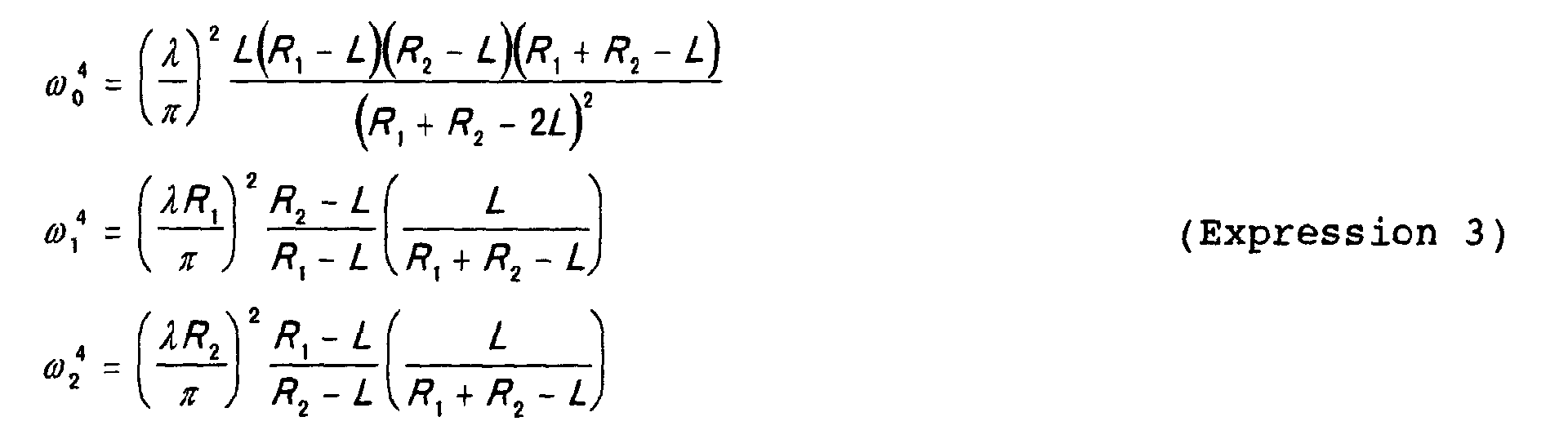
- a beam size ⁇ 0 in the position where the beam size (1/e 2 radius) of the resonance mode 5 within the laser resonator, a beam size ⁇ 1 of the resonance mode 5 in the concave reflecting mirror 2, and the beam size ⁇ 2 of the resonance mode 5 in the concave reflecting mirror 2 are expressed as the following Expression (3).
- the beam size ⁇ 0 in the position where the beam size of the resonance mode 5 becomes the smallest is decreased the smaller the resonance length L, and also as smaller the value of 2 x R-L.
- the position of ⁇ 0 where the beam size becomes the smallest becomes the center of the laser resonator, i.e., the position which is L/2 away from the concave reflecting mirror 1. From Expression (4), in order to obtain the small ⁇ 0 , there are required the short resonance length L and the concave reflecting mirror having the curvature R with which the value of 2 x R -L becomes small.
- Fig. 19 shows the relationship between the curvature R of the concave reflecting mirror, and ⁇ 0 and ⁇ 1 when the resonance length L is set to 2 m.
- the curvature R with which the value of ⁇ 0 equal to or smaller than 0.25 mm is obtained is in the range of 1.017 m to 1.000 m, and the value of ⁇ 1 at this time is in the range of 1.92 mm to ⁇ . Therefore, when the beam size is made to be small, the allowable range of the curvature R is narrow and also the beam size ⁇ 0 becomes sensitive to the change in the curvature R and the resonator length L. In addition thereto, the operation of the resonator becomes easily unstable, and hence the adjustment thereof becomes difficult. Also, since when the resonator length L is made longer with the same beam size, the operation of the resonator becomes further unstable, thus it is impossible to make the resonator length L sufficiently long.
- Fig. 20 is a schematic view showing the situation of the resonance beam mode when an inclination ⁇ occurs in the concave reflecting mirror 1.
- the misalignment occurs between the optical axis of the resonance mode and the optical axis 7 of the laser resonator.
- Fig. 21 also shows the relationship between the curvature R of the concave reflecting mirror, and ⁇ 0 and ⁇ 1 shown in Fig. 19.
- the deviation angle ⁇ 0 in the central position of the resonator is increased as the curvature R of the concave reflecting mirror 1 approaches 1.
- ⁇ 0 0.25 mm
- the resonance mode in the position of the concave reflecting mirror 1 is deviated, the eclipse of the apertures of the optical components arranged in the aperture 6 and on the optical axis occurs, the laser output is decreased and also the quality of the laser beam is degraded.
- the beam size ⁇ 1 in the position of the concave reflecting mirror 1 is 1.92 mm.
- the resonance mode 5 is perfectly refused by the aperture 6, therefore the resonance mode cannot be formed and the laser output cannot be obtained.
- the slight inclination of the concave reflecting mirror gives the optical axis of the resonance mode within the resonator a large inclination so that the stability in the emission direction of the outputted laser beam is reduced.
- a polarizer needs to be arranged on the optical path.
- the degradation of the extinction ratio of the polarizer occurs depending on the incident angle of the laser beam. For this reason, when the angular deviation of the laser beam is large, a part of the laser beam is outputted to the outside by the polarizer so that the efficiency of utilizing the laser beam is reduced.
- the birefringent material such as an EO-Q switch
- the birefringent material changes the polarization of the laser beam depending on the incident angle of the laser beam. Therefore, the resonance cannot be carried out as the laser beam so that the efficiency of utilizing the laser beam is reduced.
- the polarizer when the polarizer is arrange on the optical path of the laser beam, the extinction ratio of the polarizer is degraded depending on the incident angle of the laser beam. Therefore, there arises the problem that a part of the laser beam is outputted to the outside by the polarizer and hence the efficiency of utilizing the laser beam is reduced.
- the birefringent material such as the EO-Q switch
- the birefringent material changes the polarization of the laser beam depending on the incident angle of the laser beam. Therefore, there arises the problem that the resonance cannot be carried out as the laser beam and hence the efficiency of utilizing the laser beam is reduced.
- the present invention has been made in order to solve the problems associated with the prior art, and it is therefore an object of the present invention to provide a laser resonator in which a small beam size can be stably obtained in a long resonator length, the reduction of the efficiency of utilizing a laser beam and the quality of the laser beam can be prevented, and the emission direction of the laser beam can be stabilized.
- a laser resonator comprises: a laser material for being excited by a light source to amplify optically a laser beam; a first telescope for magnifying the laser beam which has been made incident from the laser material and for reducing the laser beam which has been made incident from the opposite side to the side of the laser material; first reflecting means for reflecting the laser beam, which has been made incident from the first telescope in the direction opposite to the incident direction; a second telescope which is arranged in such a way as to face the first telescope with the laser material sandwiched between the first telescope and the second telescope and which serves to magnify the laser beam which has been reflected by the first reflected means to be reduced by the first telescope and to be amplified by the laser material to be made incident thereto and also serves to reduce the laser beam which has been made incident from the opposite side to the side of the laser material; and second reflecting means which is arranged in such a way as to face the first reflecting means with the laser material sandwiched between the first reflecting means and the second reflecting means and which serves to
- a laser resonator comprises: a laser material for being excited by a light source to amplify optically a laser beam; a telescope for magnifying the laser beam which has been made incident from the laser material and for reducing the laser beam which has been made incident from the opposite side to the side of the laser material; first reflecting means for reflecting the laser beam, which has been made incident from the first telescope in the direction opposite to the incident direction; second reflecting means which is arranged in such a way as to face the first reflecting means with the laser material sandwiched between the first reflecting means and the second reflecting means and which serves to reflect the laser beam, which has been reflected by the first reflecting means to be reduced by the telescope and to be amplified by the laser material to be made incident thereto, in the opposite direction to the incident direction.
- a laser resonator comprises: a laser material for being excited by a light source to amplify optically a laser beam; a first telescope for magnifying the laser beam which has been made incident from the laser material and for reducing the laser beam which has been made incident from the opposite side to the side of the laser material; a second telescope for magnifying the laser beam which has been made incident from the first telescope and for reducing the laser beam which has been made incident from the opposite side to the side of the first telescope; first reflecting means for reflecting the laser beam, which has been made incident from the second telescope, in the opposite direction to the incident direction; a third telescope which is arranged in such a way as to face the first telescope with the laser material sandwiched between the first telescope and the second telescope and which serves to magnify the laser beam which has been reflected by the first reflecting means to be reduced by the first and second telescopes and to be amplified by the laser material to be made incident thereto and also serves to reduce the laser beam which has been made incident from the opposite side to the side
- a laser resonator in which the first reflecting means is comprised of a first roof prism having two reflecting surfaces intersecting perpendicularly to each other and a first edge line defined between the two reflecting surfaces; the second reflecting means is comprised of a second roof prism having two reflecting surfaces intersecting perpendicularly to each other and a second edge line defined between the two reflecting surfaces; and the first and second roof prisms are arranged in such a way that the first and second edge lines intersect perpendicularly to each other.
- each of the telescopes includes a first lens which is arranged in the opposite side to the side of the laser material and has a positive focal length f 1 and a second lens which is arranged on the side of the laser material and has a positive focal length f 2 , and fulfills the relationship of
- each of the telescopes includes a first lens which is arranged in the opposite side to the side of the laser material and has a positive focal length f 1 and a second lens which is arranged on the side of the laser material and has a negative focal length f 2 , and fulfills the relationship of
- a laser resonator according to a seventh aspect of the present invention in which the telescope(s) adjacent to the laser material is/are arranged in such a way that a distance from the second lens to the center of the laser resonator is roughly equal to the focal length f 2 of the second lens.
- each of the telescopes includes: a first lens which is arranged on the opposite side to the side of the laser material and has a focal length f 1 ; and a second lens which is arranged on the side of the laser material and has a focal length f 2 , and fulfills the relationship of
- a laser resonator according to a ninth aspect of the present invention in which the aperture for selecting among the resonator modes is an optical component.
- a laser resonator according to a tenth aspect of the present invention, in which instead of the aperture for selecting among the resonator modes, an output coupling device for taking out a part of the laser beam to the outside is arranged.
- a laser resonator according to an eleventh aspect of the present invention in which the first telescope and the third telescope are detachable.
- a laser resonator according to a twelfth aspect of the present invention, in which further comprising a switching device having a second laser material for being excited by a second light source to amplify optically the laser beam, wherein the laser material, the first telescope, and the third telescope are all detached, and the switching device is arranged roughly at the center of the resonator.
- a laser resonator according to a thirteenth aspect of the present invention, in which a polarizer is arranged on an optical path between each of the reflecting means and the telescope(s) arranged on the side of the reflecting means.
- a laser resonator according to a fourteenth aspect of the present invention in which a double refractive device is arranged on the optical path between each of the reflecting means and the telescope(s) arranged on the side of the reflecting means.
- a laser resonator according to a fifteenth aspect of the present invention in which the laser material has the thermal lens effect.
- a laser resonator according to a sixteenth aspect of the present invention in which the laser material has the thermal lens effect which has two different focal lengths within the face perpendicular to an optical axis of the laser resonator.
- a laser resonator in which the laser material uses any one of (Er: Glass), (Er, Yb: Glass), (Er: YAG), (Tm: YAG), (Tm, Ho: YAG), (Ho: YLF) or (Tm, Ho: YLF).
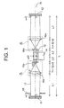
- FIG. 1 is a schematic view showing the construction of a laser resonator according to Embodiment 1 of the present invention.
- the same or corresponding parts are denoted with the same reference numerals.
- reference numerals 11 and 12 denote plane reflecting mirrors, respectively; reference numeral 13 denotes a laser material; reference numeral 14 denotes a pump light source for exciting the laser material 13; reference numeral 15 denotes a telescope having lenses 15a and 15b; reference numeral 16 denotes a telescope having lenses 16a and 16b; reference numeral 17 denotes a resonance mode within a laser resonator; and reference numeral 18 denotes an aperture for limiting the resonance mode 17.
- the plane reflecting mirrors 11 and 12 are arranged in a symmetrical style with the laser material 13 as the center.
- the telescope 15 is arranged between the plane reflecting mirror 11 and the laser material 13.
- a focal length of the lens 15a of the telescope 15 is f 1
- a focal length of the lens 15b of the telescope 15 is f 2
- an interval between the lends 15a and the lends 15b is f 1 + f 2 + ⁇ .
- > 1 is established.
- the same optical component is employed for the telescope 15 and the telescope 16 which are in turn arranged symmetrically with the laser material 13 as the center.
- the lens 15a and the plane reflecting mirror 1, and the lens 16a and the plane reflecting mirror 12 are arranged in such a way that a distance between the lens 15a and the plane reflecting mirror 1 and a distance between the lens 16a and the plane reflecting mirror 12 becomes each L 1 .
- the laser beam which has been emitted in the direction towards the telescope 15 through the laser material 13 is magnified by the telescope 15 to be propagated to be reflected in the opposite direction to the incident laser beam by the plane reflecting mirror 11. Then, the laser beam which has been reflected by the plane reflecting mirror 11 is reduced by the telescope 15 to be made incident to the laser material 13 again. Further, after the laser beam which has been made incident to the laser material 13 passes through the laser material 13 to be optically amplified, it is magnified by the telescope 16 to be propagated to be reflected in the opposite direction to the incident laser beam by the plane reflecting mirror 12. The laser beam which has been reflected by the plane reflecting mirror 12 is reduced by the telescope 16 to be made incident to the laser material 13 again.
- the laser beam is further optically amplified by the laser material 13. That is, the laser beam which has been emitted from the laser material 13 makes a round through the same optical path to be returned back to the laser material 13 to thereby be confined in the laser resonator.
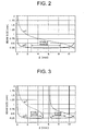
- the lens interval difference ⁇ in which ⁇ 0 is equal to or smaller than 0.25 mm is obtained is in the range of 2.7 mm to 8.4 mm, and hence it is understood that the stable beam size is obtained over a wide range.
- ⁇ 1 at this time is in the range of 0.87 mm to 0.49 mm.
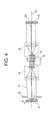
- Fig. 4 is a schematic view showing the situation of the resonance beam mode when an inclination ⁇ occurs in the plane reflecting mirror 11, the misalignment occurs between the optical axis 20 of the resonance mode and the optical axis 19 of the laser resonator.
- the deviation amount of the optical axis in the plane reflecting mirror is d 1
- the deviation angle of the optical axis in the plane reflecting mirror 11 is ⁇ 1
- the deviation amount of the optical axis in the resonator center is d 0
- the deviation angle of optical axis in the resonator center is ⁇ 1 , d 0 , ⁇ 1 , d 1 , and ⁇ 1 are respectively expressed by the following Expression (7).
- fig. 5 also shows the relationship between the lens interval difference ⁇ , and ⁇ 0 and ⁇ 1 shown in Fig. 2.
- ⁇ 0 and ⁇ 1 are both constant independent of the values of ⁇ , and hence ⁇ 0 is 200 ⁇ rad and ⁇ 1 is 100 ⁇ rad.
- all of ⁇ 0 , d 0 and ⁇ 0 are not largely changed in the range of L 1 from 0 to 0.05m.
- the resonator can be constructed in which even when L 2 ⁇ f 2 , the influence by the inclination of the plane reflecting mirror is insignificant.
- the telescope having a suitable magnification M can be selected for the resonator length, a stable resonator which ahs a small beam size in spite of the long resonator length can be constructed.
- a stable resonator can be constructed in which the reduction of the laser output due to the alignment deviation is prevented and also the reduction of the laser beam quality due to the diffraction of the eclipse is prevented.
- a small laser material can be used in correspondence to a small beam size
- a laser employing a laser material having a small gain inherent in a material e.g., the laser material, which oscillates with the eye-safe wavelength, such as Er: Glass (the oscillation wavelength is 1.5 ⁇ m), Er, Yb: Glass (the oscillation wavelength is 1.5 ⁇ m), Er: YAG (the oscillation wavelength is 1.6 ⁇ m), Tm: YAG (the oscillation wavelength is 2 ⁇ m), Tm, Ho: YAG (the oscillation wavelength is 2 ⁇ m), Ho: YLF (the oscillation wavelength is 2 ⁇ m), or Tm, Ho: YLF (the oscillation wavelength is 2 ⁇ m), the efficiency of utilizing the laser beam can be enhanced.
- a polarizer for defining the polarization direction of the laser beam may be arranged either between the plane reflecting mirror 11 and the telescope 15, or between the plane reflecting mirror 12 and the telescope 16.
- a birefringent material such as an EO-Q switch, for carrying out the pulse driving may be arranged either between the plane reflecting mirror 11 and the telescope 15 or between the plane reflecting mirror 12 and the telescope 16.
- a laser resonator can be constructed in which the degradation of the extinction ratio of the laser beam becomes less and also the efficiency of utilizing the laser beam is high.
- Fig. 10 is a schematic view showing the construction of a self-compensation type laser resonator according to Embodiment 2 of the present invention.
- reference numeral 22 denoted a laser material which has a focal length f r and has the thermal lens effect.
- Other constituent elements are the same as those in the above-mentioned Embodiment 1.
- f 1 /f 2 M
- L2 f 2 is assumed.
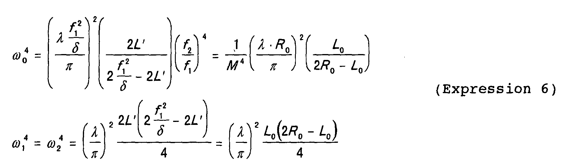
- Expression (8) is in the form in which ⁇ in Expression (6) is replaced with ( ⁇ + f 2 2 /2f r ). That is, if the laser material 22 is inserted in the resonator, a resonator can be configured which has a beam size ⁇ 0 that is identical with a beam size before the laser material 22 is inserted in the resonator by changing ⁇ such that ⁇ of the resonator before the insertion and ( ⁇ + f 2 2 /2f r ) after the insertion is the same. In addition, changes in a beam size and an optical axis of a beam due to an inclination of the plane reflecting mirror 11 will be the same before and after the insertion.
- a stable resonator having a small beam size with a large length can be configured.
- a stable resonator can be configured in which decrease of a laser output due to misalignment is prevented and degradation of a laser beam quality due to diffraction of an eclipse is also prevented.
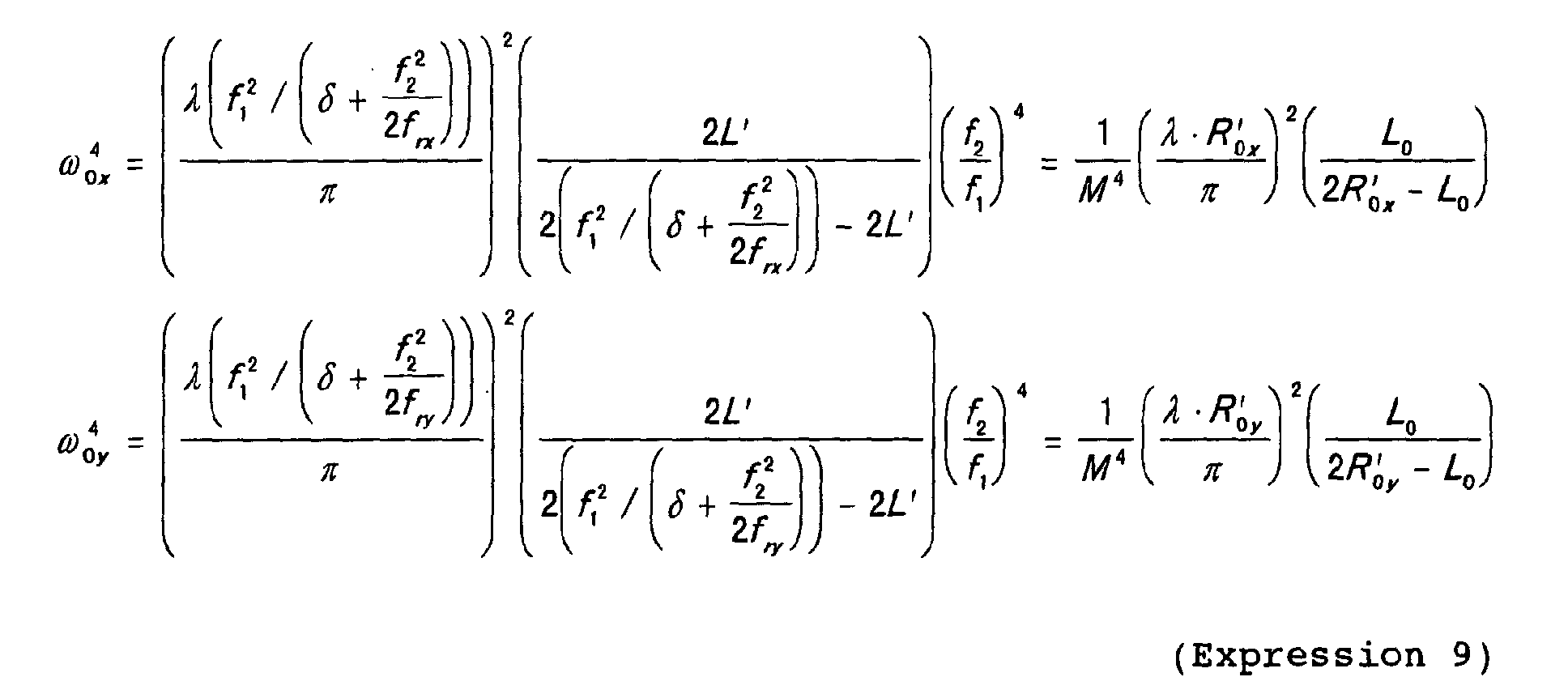
- a case in which focal lengths of thermal lens of the laser material 22 are different in the x axis direction and the y axis direction is considered. Since a beam size on the laser material 22 in a resonating mode changes according to a focal length of a laser material, if a focal length is different in the x axis direction and the y axis direction, a beam size on the laser material is different in general. At this point, since an overlap of the resonating mode and the laser material 22 worsens, an efficiency of taking out energy from the laser material 22 declines and a utilization efficiency of a laser beam declines.
- a beam size ⁇ 0x in the x axis direction and a beam size ⁇ 0y in the y axis direction of the resonating mode at a center of the resonator is represented by Expression (9) shown below.
- f 1 2 / ( ⁇ + f 2 2 /2f rx ) R 0x '
- f 1 2 / ( ⁇ + f 2 2 /2f ry ) R 0y ' .
- Fig. 11 is a schematic view showing a configuration of a laser resonator in accordance with Embodiment 3 of the present invention.
- reference numeral 23 denotes an aperture disposed in a position which is apart from a plane reflecting mirror 11 by a distance L p , and the figure illustrates a state of a resonating beam mode when an inclination ⁇ occurs in the plane reflecting mirror 11.
- Other configurations are the same as those in Embodiment 1.
- a deviation amount d p of an optical axis and a deviation angle ⁇ p of the optical axis in a position of the aperture 23 are represented by Expression (11) shown below.
- d p is always 0 regardless of the inclination ⁇ of the plane reflecting mirror 11. That is, if an inclination occurs in the plane reflecting mirror 11, since a position of a beam is not deviated in the position of the aperture 23, a loss due to an eclipse is not generated.
- a stable resonator can be configured in which decline of a laser output due to a misalignment is prevented and degradation of a laser beam due to diffraction of an eclipse is prevented.
- an optical component such as a polarizer, a wave plate, an EO-Q switch, AO-Q switch or the like may be arranged.
- an eclipse due to an aperture of an optical component does not occur regardless of an inclination amount of the plane reflecting mirror 11, a stable resonator can be configured in which decline of a laser output due to a misalignment is prevented and degradation of a laser beam due to diffraction of an eclipse is prevented.
- an output coupling device for taking out a part of a laser may be arranged instead of the aperture 23.
- Fig. 12 is a schematic view showing a configuration of a laser resonator in accordance with Embodiment 4 of the present invention.
- reference numerals 35 and 36 denote plane reflecting mirror
- reference numeral 37 denotes a telescope having lenses 37a and 37b
- reference numeral 38 denotes a laser material
- reference numeral 39 denotes an exciting light source for exciting the laser material 38.
- the plane reflecting mirrors 35 and 36 are arranged opposing each other, and the laser material 38 is disposed on the side of the plane reflecting mirror 36.
- the telescope 37 is arranged between the plane reflecting mirror 35 and the laser material 38, and a focal length of the lens 37a of the telescope 37 is f 1 , a focal length of the lens 37b of the telescope 37 is f 2 and an interval between the lens 37a and the lens 37b is f 1 + f 2 + ⁇ .
- a distance between the lens 37a and the plane reflecting mirror 35 is L 1
- a distance between the lens 37b and the plane reflecting mirror 36 is L 2 .
- a laser beam emitted from the laser material 38 to the direction of the telescope 37 is magnified by the telescope 37 and propagated, and is reflected by the plane reflecting mirror 35 to the direction opposite the incident laser beam.
- the laser beam reflected by the plane reflecting mirror 35 is reduced by the telescope 37, and is incident in the laser material 38 again.
- the laser beam incident in the laser material 38 is reflected by the plane reflecting mirror 36, incident in the laser material 38 again, and is further amplified by the laser material 38. That is, the laser beam emitted from the laser material 38 goes back and forth the same optical path and returns to the laser material 38, and is confined in the laser resonator.
- a stable resonator having a small beam size with a large length can be configured.
- a stable resonator can be configured in which decline of a laser output due to misalignment is prevented and degradation of a laser beam due to diffraction of an eclipse is also prevented.
- the number of optical components is approximately a half of those shown in Fig. 1, a circulation loss of the resonator is reduced and utilization efficiency of a laser beam can be improved.
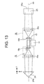
- Fig. 13 is a schematic view showing a configuration of a laser resonator in accordance with Embodiment 5 of the present invention.
- reference numeral 24 denotes a roof prism having an edge line 24a that is parallel to the y axis
- reference numeral 25 denotes a roof prism having an edge line 25a that is parallel to the x axis.
- Other configurations are the same as those in Embodiment 1.
- Fig. 14 is a schematic view showing a reflection state of a laser beam incident on the roof prism 24 of Fig. 13.
- reflection faces 24b and 24c sandwiching the edge line 24a are fixed perpendicular to each other, and forms an angle of 45 degrees with an optical axis 19.
- a laser beam that travels on an optical path 26 parallel to the optical axis 19 and is incident on the roof prism 24 is given changes of direction of a total 180 degrees consisting of 90 degrees by the reflection face 24b and 90 degrees by the reflection face 24c.
- An optical path 27 of the laser beam reflected in this way is also parallel to the optical axis 19. That is, the roof prism 24 reflects an incident laser beam as a laser beam that is parallel to the incident laser beam and travels in an opposite direction.
- the roof prism 24 also reflects the incident laser beam as a laser beam that is parallel to the incident laser beam and travels in an opposite direction.
- the optical paths 26 and 27 are shown as shifted from the optical axis 19 in Figs. 14 and 15 for illustration purpose, in practice, a center of a beam of either the optical path 26 or the optical path 27 coincides with the optical path 19, and a laser beam is irradiated on an area including the edge line 24a and reflected.
- a stable resonator can be configured in which decline of a laser output due to misalignment is prevented.
- Fig. 16 is a schematic view showing a configuration of a laser resonator in accordance with Embodiment 6 of the present invention.
- reference numeral 28 denotes a telescope having lenses 28a and 28b
- reference numeral 29 denotes a telescope having lenses 29a and 29b
- reference numeral 30 denotes a telescope having lenses 30a and 30b
- reference numeral 31 denotes a telescope having lenses 31a and 31b.
- Other configurations are the same as those of the above-mentioned Embodiment 1.
- a focal length of the lens 28a of the telescope 28 is f 1
- a focal length of the lens 28b of the telescope 28 is f 2
- an interval between these lenses 28a and 28b is f 1 +f 2 + ⁇ 1 .
- f 1 /f 2 >1.
- a focal length of the lens 30a of the telescope 30 is f 3
- a focal length of the lens 30b of the telescope 30 is f 4
- an interval between these lenses 30a and 30b is f 3 +f 4 + ⁇ 2 .
- f 3 /f 4 > 1.
- Identical telescopes are used as the telescope 28 shown on the left side of the figure and the telescope 29 shown on the right side, which are arranged in symmetry with a laser material 13 as a center.
- identical telescopes are used as the telescope 30 shown on the left side of the figure and the telescope 31 on the right side, which are arranged in symmetry with the laser material 13 as a center, and the telescope 30 is arranged between the telescope 28 and the laser material 13 and the telescope 31 is arranged between the telescope 29 and the laser material 13, respectively.
- the lens 28a and the plane reflecting mirror 11 as well as the lens 29a and the plane reflecting mirror 12 are arranged such that distances between the lenses and the plane reflecting mirrors are L 1 respectively.
- the lens 28b and the lens 30a as well as the lens 29a and the lens 31a are arranged such that distances between the pairs of lenses are L 2 respectively.
- the lens 30b and the resonator as well as the lens 31b and the resonator are arranged such that distances between the lenses and centers of the resonators are L 3 respectively.
- a laser beam emitted from the laser material 13 in the direction of the telescope 30 is magnified by the telescope 30 and propagates, and is incident on the telescope 28.
- the laser beam incident on the telescope 28 is magnified by the telescope 28 and propagates, and is reflected by the plane reflecting mirror 11 in the direction opposite to the incident laser beam.
- the laser beam reflected by the plane reflecting mirror 11 is reduced by the telescope 28 and the telescope 30, and is incident on the laser material 13 again. Moreover, the laser beam incident on the laser material 13, after passing through the laser material 13 and amplified, is magnified by the telescopes 31 and 29 and propagates, and is reflected by the plane reflecting mirror 12 in the direction opposite to the incident laser beam.
- the laser beam reflected by the plane reflecting mirror 12 is reduced by the telescope 29 and the telescope 31, incident on the laser material 13 again, and is further amplified by the laser material 13. That is, the laser beam emitted from the laser material 13 goes back and forth the same optical path and returns to the laser material 13, and is confined in the laser resonator.
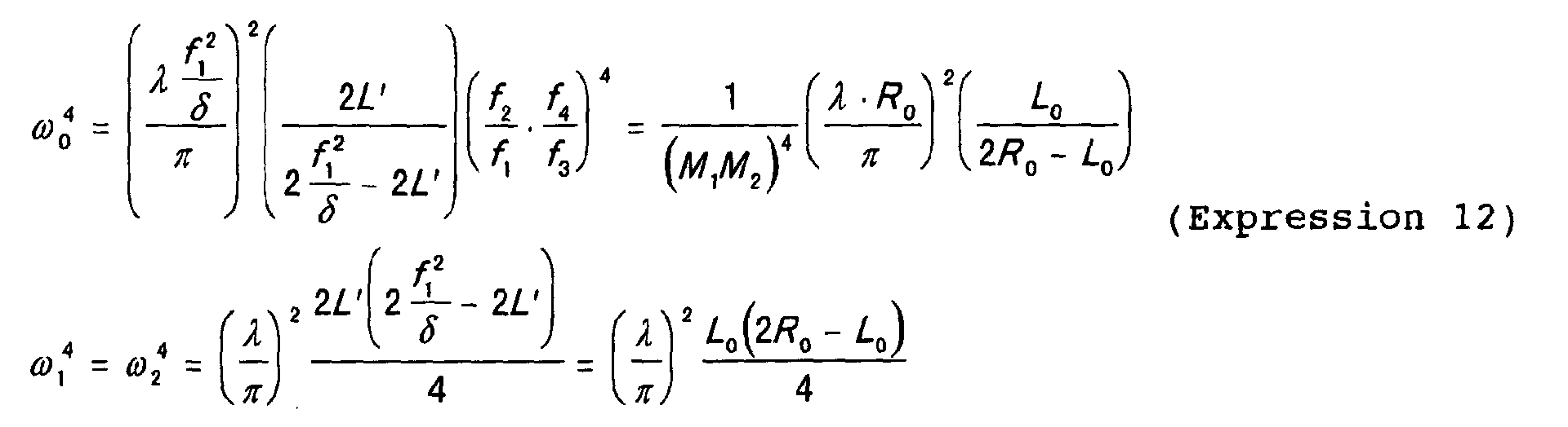
- Expression (12) is in the form in which M in Expression (6) is replaced with (M 1 x M 2 ). That is, if the telescope 30 and the telescope 31 are inserted in the resonator, a size of the resonating mode at the center of the resonator before the insertion is reduced by 1/M 2 times.
- changes of a beam size and a beam with respect to an optical axis due to an inclination of the plane reflecting mirror 11 may be found by replacing M in Expression (7) with (M 1 x M 2 ). That is, a resonating mode of an arbitrary beam size ⁇ 0 can be given by a combination of M 1 and M 2 .
- a stable resonator having a small beam size with a large length can be configured.
- a stable resonator can be configured in which decline of a laser output due to misalignment is prevented and degradation of a laser beam due to diffraction of an eclipse is also prevented.
- the beam size ⁇ 0 in a center of the resonator can be made larger. Therefore, a laser resonator having two kinds of beam sizes ⁇ 0 in one body can be configured. If the beam size ⁇ 0 is changed on the laser material 13, an output of a laser beam, a beam quality, a pulse width and the like change.
- a laser resonator can be configured in which an output of a laser beam, a beam quality and a pulse width can be changed.
- a laser resonator with such a configuration, since two kinds of beam sizes of a resonating mode can be given to different laser materials, a laser resonator can be configured in which a wave length, an output, a beam quality, a pulse width or the like of a laser beam can be changed.
- a laser resonator can be configured in which an output of a laser beam, a beam quality and a pulse with in m kinds of ways can be changed.
Landscapes
- Physics & Mathematics (AREA)
- Electromagnetism (AREA)
- Engineering & Computer Science (AREA)
- Plasma & Fusion (AREA)
- Optics & Photonics (AREA)
- Lasers (AREA)
Abstract
Description





Claims (17)
- A laser resonator comprising:a laser material for being excited by a light source to amplify optically a laser beam;a first telescope for magnifying the laser beam which has been made incident from said laser material and for reducing the laser beam which has been made incident from the opposite side to the side of said laser material;first reflecting means for reflecting the laser beam, which has been made incident from said first telescope in the direction opposite to the incident direction;a second telescope which is arranged in such a way as to face said first telescope with said laser material sandwiched between said first telescope and said second telescope and which serves to magnify the laser beam which has been reflected by said first reflected means to be reduced by said first telescope and to be amplified by said laser material to be made incident thereto and also serves to reduce the laser beam which has been made incident from the opposite side to the side of said laser material; andsecond reflecting means which is arranged in such a way as to face said first reflecting means with said laser material sandwiched between said first reflecting means and said second reflecting means and which serves to reflect the laser beam, which has been made incident from said second telescope, in the opposite direction to the incident direction.
- A laser resonator comprising:a laser material for being excited by a light source to amplify optically a laser beam;a telescope for magnifying the laser beam which has been made incident from said laser material and for reducing the laser beam which has been made incident from the opposite side to the side of said laser material;first reflecting means for reflecting the laser beam, which has been made incident from said first telescope in the direction opposite to the incident direction; andsecond reflecting means which is arranged in such a way as to face said first reflecting means with said laser material sandwiched between said first reflecting means and said second reflecting means and which serves to reflect the laser beam, which has been reflected by said first reflecting means to be reduced by said telescope and to be amplified by said laser material to be made incident thereto, in the opposite direction to the incident direction.
- A laser resonator comprising:a laser material for being excited by a light source to amplify optically a laser beam;a first telescope for magnifying the laser beam which has been made incident from said laser material and for reducing the laser beam which has been made incident from the opposite side to the side of said laser material;a second telescope for magnifying the laser beam which has been made incident from said first telescope and for reducing the laser beam which has been made incident from the opposite side to the side of said first telescope;first reflecting means for reflecting the laser beam, which has been made incident from said second telescope, in the opposite direction to the incident direction;a third telescope which is arranged in such a way as to face said first telescope with said laser material sandwiched between said first telescope and said second telescope and which serves to magnify the laser beam which has been reflected by said first reflecting means to be reduced by said first and second telescopes and to be amplified by said laser material to be made incident thereto and also serves to reduce the laser beam which has been made incident from the opposite side to the side of said laser material;a fourth telescope which is arranged in such a way as to face said second telescope with said laser material sandwiched between said second telescope and said fourth telescope and which serves to magnify the laser beam which has been made incident from said third telescope and to serve to reduce the laser beam which has been made incident from the opposite side to the side of said third telescope; andsecond reflecting means which is arranged in such a way as to face said first reflecting means with said laser material sandwiched between said first reflecting means and said second reflecting means and which serves to reflect the laser beam, which has been made incident from said fourth telescope, in the opposite direction to the incident direction.
- A laser resonator according to any one of claims 1 to 3, wherein said first reflecting means is comprised of a first roof prism having two reflecting surfaces intersecting perpendicularly to each other and a first edge line defined between said two reflecting surfaces;said second reflecting means is comprised of a second roof prism having two reflecting surfaces intersecting perpendicularly to each other and a second edge line defined between said two reflecting surfaces; andsaid first and second roof prisms are arranged in such a way that said first and second edge lines intersect perpendicularly to each other.
- A laser resonator according to any one of claims 1 to 4, wherein each of said telescopes includes a first lens which is arranged in the opposite side to the side of said laser material and has a positive focal length f1 and a second lens which is arranged on the side of said laser material and has a positive focal length f2, and fulfills the relationship of |f1/f2| > 1.
- A laser resonator according to any one of claims 1 to 4, wherein each of said telescopes includes a first lens which is arranged in the opposite side to the side of said laser material and has a positive focal length fl and a second lens which is arranged on the side of said laser material and has a negative focal length f2, and fulfills the relationship of |f1/f2| > 1.
- A laser resonator according to claim 5, wherein said telescope(s) adjacent to said laser material is/are arranged in such a way that a distance from said second lens to the center of said laser resonator is roughly equal to the focal length f2 of said second lens.
- A laser resonator according to claims 1 or 2, wherein each of said telescopes includes: a first lens which is arranged on the opposite side to the side of said laser material and has a focal length fl; and a second lens which is arranged on the side of said laser material and has a focal length f2, and fulfills the relationship of |f1/f2| > 1,an aperture for selecting among the resonator modes is arranged between said first reflecting means and said telescopes(s) arranged on the side of said first reflecting means, andwhen a distance between said first reflecting means and said telescope(s) arranged on the side of said first reflecting means is L1, and a distance between said first lens of said telescope arranged on the side of said first reflecting means and said second lens is f1 + f2 + δ, a distance between said first reflecting means and said aperture is L1 - f1 - f1 x f1/(2 x δ).
- A laser resonator according to claim 8, wherein said aperture for selecting among the resonator modes is an optical component.
- A laser resonator according to claim 8, wherein instead of said aperture for selecting among the resonator modes, an output coupling device for taking out a part of the laser beam to the outside is arranged.
- A laser resonator according to claim 3, wherein said first telescope and said third telescope are detachable.
- A laser resonator according to claim 3, further comprising a switching device having a second laser material for being excited by a second light source to amplify optically the laser beam,
wherein said laser material, said first telescope, and said third telescope are all detached, and said switching device is arranged roughly at the center of said resonator. - A laser resonator according to any one of claims 1 to 12, wherein a polarizer is arranged on an optical path between each of said reflecting means and said telescope(s) arranged on the side of said reflecting means.
- A laser resonator according to any one of claims 1 to 12, wherein a birefringent device is arranged on the optical path between each of said reflecting means and said telescope(s) arranged on the side of said reflecting means.
- A laser resonator according to any one of claims 1 to 14, wherein said laser material has the thermal lens effect.
- A laser resonator according to any one of claims 1 to 14, wherein said laser material has the thermal lens effect which has two different focal lengths within the face perpendicular to an optical axis of said laser resonator.
- A laser resonator according to any one of claims 1 to 16, wherein said laser material uses any one of (Er: Glass), (Er, Yb: Glass), (Er: YAG), (Tm: YAG), (Tm, Ho: YAG), (Ho: YLF) or (Tm, Ho: YLF).
Applications Claiming Priority (2)
| Application Number | Priority Date | Filing Date | Title |
|---|---|---|---|
| JP2000086605A JP3621623B2 (en) | 2000-03-27 | 2000-03-27 | Laser resonator |
| JP2000086605 | 2000-03-27 |
Publications (3)
| Publication Number | Publication Date |
|---|---|
| EP1139520A2 true EP1139520A2 (en) | 2001-10-04 |
| EP1139520A3 EP1139520A3 (en) | 2004-08-04 |
| EP1139520B1 EP1139520B1 (en) | 2009-08-05 |
Family
ID=18602739
Family Applications (1)
| Application Number | Title | Priority Date | Filing Date |
|---|---|---|---|
| EP01106799A Expired - Lifetime EP1139520B1 (en) | 2000-03-27 | 2001-03-19 | Laser resonator |
Country Status (4)
| Country | Link |
|---|---|
| US (1) | US20010028672A1 (en) |
| EP (1) | EP1139520B1 (en) |
| JP (1) | JP3621623B2 (en) |
| DE (1) | DE60139434D1 (en) |
Cited By (2)
| Publication number | Priority date | Publication date | Assignee | Title |
|---|---|---|---|---|
| EP1681749A1 (en) * | 2005-01-17 | 2006-07-19 | Fanuc Ltd | Laser oscillator |
| AT515530B1 (en) * | 2013-08-12 | 2015-10-15 | Daniel Dr Kopf | Q-switched solid state laser |
Families Citing this family (9)
| Publication number | Priority date | Publication date | Assignee | Title |
|---|---|---|---|---|
| US20050185691A1 (en) * | 2003-07-18 | 2005-08-25 | Slater Richard C. | Coherent beam combination |
| JP4069894B2 (en) | 2004-03-30 | 2008-04-02 | 三菱電機株式会社 | Solid state laser equipment |
| JP2007012981A (en) * | 2005-07-01 | 2007-01-18 | National Institute Of Information & Communication Technology | Laser device with highly reflective coating on the internal total reflection surface of optical element |
| JP5339172B2 (en) * | 2006-11-15 | 2013-11-13 | 株式会社メガオプト | Coherent doppler rider |
| JP5387875B2 (en) * | 2008-03-06 | 2014-01-15 | 株式会社Ihi | Laser resonator |
| JP2011203156A (en) * | 2010-03-26 | 2011-10-13 | Dainippon Screen Mfg Co Ltd | Distance measuring device |
| AT510116B1 (en) * | 2010-06-22 | 2012-06-15 | High Q Laser Gmbh | LASER |
| EP2614560B1 (en) * | 2010-10-29 | 2023-05-31 | Lawrence Livermore National Security, LLC | Method and system for compact efficient laser architecture |
| JP2014086531A (en) * | 2012-10-23 | 2014-05-12 | Canon Inc | Laser device and control method thereof |
Family Cites Families (3)
| Publication number | Priority date | Publication date | Assignee | Title |
|---|---|---|---|---|
| US3426294A (en) * | 1965-02-10 | 1969-02-04 | American Optical Corp | Laser q-switching |
| US3777280A (en) * | 1971-09-20 | 1973-12-04 | Ibm | Laser generator of te wave guide modes |
| US4803694A (en) * | 1987-07-08 | 1989-02-07 | Amada Company, Limited | Laser resonator |
-
2000
- 2000-03-27 JP JP2000086605A patent/JP3621623B2/en not_active Expired - Fee Related
-
2001
- 2001-03-19 DE DE60139434T patent/DE60139434D1/en not_active Expired - Lifetime
- 2001-03-19 EP EP01106799A patent/EP1139520B1/en not_active Expired - Lifetime
- 2001-03-22 US US09/814,115 patent/US20010028672A1/en not_active Abandoned
Cited By (3)
| Publication number | Priority date | Publication date | Assignee | Title |
|---|---|---|---|---|
| EP1681749A1 (en) * | 2005-01-17 | 2006-07-19 | Fanuc Ltd | Laser oscillator |
| AT515530B1 (en) * | 2013-08-12 | 2015-10-15 | Daniel Dr Kopf | Q-switched solid state laser |
| AT515530A4 (en) * | 2013-08-12 | 2015-10-15 | Daniel Dr Kopf | Q-switched solid state laser |
Also Published As
| Publication number | Publication date |
|---|---|
| EP1139520A3 (en) | 2004-08-04 |
| JP3621623B2 (en) | 2005-02-16 |
| DE60139434D1 (en) | 2009-09-17 |
| US20010028672A1 (en) | 2001-10-11 |
| JP2001274491A (en) | 2001-10-05 |
| EP1139520B1 (en) | 2009-08-05 |
Similar Documents
| Publication | Publication Date | Title |
|---|---|---|
| EP0452069B1 (en) | Ring laser | |
| US5199042A (en) | Unstable laser apparatus | |
| US4016504A (en) | Optical beam expander for dye laser | |
| JP3265173B2 (en) | Solid state laser device | |
| US5995523A (en) | Single mode laser suitable for use in frequency multiplied applications and method | |
| US3638139A (en) | Frequency-selective laser devices | |
| EP1139520B1 (en) | Laser resonator | |
| JP2006156782A (en) | Laser oscillator | |
| US5125001A (en) | Solid laser device | |
| US20060114947A1 (en) | Solid-state laser generator | |
| KR970005169B1 (en) | Self aligning internal cavity Raman laser | |
| EP0587330A1 (en) | Wavelength conversion apparatus | |
| JP3211770B2 (en) | Solid-state laser device and solid-state laser amplifier having the same | |
| US6853670B2 (en) | Laser resonator | |
| US20220102933A1 (en) | Laser apparatus | |
| US6901102B1 (en) | Self-compensating laser resonator | |
| US6282224B1 (en) | Non-planar Q-switched ring laser system | |
| WO1990012435A1 (en) | Ring laser | |
| EP0692152B1 (en) | Unstable resonator laser apparatus | |
| JPH06204591A (en) | Solid laser device | |
| JPH1115033A (en) | Laser light harmonic generator | |
| US6778579B2 (en) | Solid-state laser compensated for pumping-light astigmatism | |
| JP3031740B2 (en) | Harmonic generator | |
| JPH0927648A (en) | Sum frequency laser equipment | |
| JPH08250787A (en) | Solid-state laser oscillator |
Legal Events
| Date | Code | Title | Description |
|---|---|---|---|
| PUAI | Public reference made under article 153(3) epc to a published international application that has entered the european phase |
Free format text: ORIGINAL CODE: 0009012 |
|
| AK | Designated contracting states |
Kind code of ref document: A2 Designated state(s): AT BE CH CY DE DK ES FI FR GB GR IE IT LI LU MC NL PT SE TR |
|
| AX | Request for extension of the european patent |
Free format text: AL;LT;LV;MK;RO;SI |
|
| PUAL | Search report despatched |
Free format text: ORIGINAL CODE: 0009013 |
|
| AK | Designated contracting states |
Kind code of ref document: A3 Designated state(s): AT BE CH CY DE DK ES FI FR GB GR IE IT LI LU MC NL PT SE TR |
|
| AX | Request for extension of the european patent |
Extension state: AL LT LV MK RO SI |
|
| 17P | Request for examination filed |
Effective date: 20040813 |
|
| AKX | Designation fees paid |
Designated state(s): DE FR GB |
|
| RBV | Designated contracting states (corrected) |
Designated state(s): DE FR GB |
|
| RAP1 | Party data changed (applicant data changed or rights of an application transferred) |
Owner name: MITSUBISHI DENKI KABUSHIKI KAISHA |
|
| 17Q | First examination report despatched |
Effective date: 20070712 |
|
| GRAP | Despatch of communication of intention to grant a patent |
Free format text: ORIGINAL CODE: EPIDOSNIGR1 |
|
| GRAS | Grant fee paid |
Free format text: ORIGINAL CODE: EPIDOSNIGR3 |
|
| GRAA | (expected) grant |
Free format text: ORIGINAL CODE: 0009210 |
|
| AK | Designated contracting states |
Kind code of ref document: B1 Designated state(s): DE FR GB |
|
| REG | Reference to a national code |
Ref country code: GB Ref legal event code: FG4D |
|
| REF | Corresponds to: |
Ref document number: 60139434 Country of ref document: DE Date of ref document: 20090917 Kind code of ref document: P |
|
| PLBE | No opposition filed within time limit |
Free format text: ORIGINAL CODE: 0009261 |
|
| STAA | Information on the status of an ep patent application or granted ep patent |
Free format text: STATUS: NO OPPOSITION FILED WITHIN TIME LIMIT |
|
| 26N | No opposition filed |
Effective date: 20100507 |
|
| PGFP | Annual fee paid to national office [announced via postgrant information from national office to epo] |
Ref country code: FR Payment date: 20120319 Year of fee payment: 12 |
|
| PGFP | Annual fee paid to national office [announced via postgrant information from national office to epo] |
Ref country code: GB Payment date: 20120314 Year of fee payment: 12 |
|
| PGFP | Annual fee paid to national office [announced via postgrant information from national office to epo] |
Ref country code: DE Payment date: 20120411 Year of fee payment: 12 |
|
| GBPC | Gb: european patent ceased through non-payment of renewal fee |
Effective date: 20130319 |
|
| REG | Reference to a national code |
Ref country code: FR Ref legal event code: ST Effective date: 20131129 |
|
| REG | Reference to a national code |
Ref country code: DE Ref legal event code: R119 Ref document number: 60139434 Country of ref document: DE Effective date: 20131001 |
|
| PG25 | Lapsed in a contracting state [announced via postgrant information from national office to epo] |
Ref country code: GB Free format text: LAPSE BECAUSE OF NON-PAYMENT OF DUE FEES Effective date: 20130319 Ref country code: FR Free format text: LAPSE BECAUSE OF NON-PAYMENT OF DUE FEES Effective date: 20130402 Ref country code: DE Free format text: LAPSE BECAUSE OF NON-PAYMENT OF DUE FEES Effective date: 20131001 |