EP1139507A1 - Electrical noise-reducing assembly and member - Google Patents
Electrical noise-reducing assembly and member Download PDFInfo
- Publication number
- EP1139507A1 EP1139507A1 EP01302608A EP01302608A EP1139507A1 EP 1139507 A1 EP1139507 A1 EP 1139507A1 EP 01302608 A EP01302608 A EP 01302608A EP 01302608 A EP01302608 A EP 01302608A EP 1139507 A1 EP1139507 A1 EP 1139507A1
- Authority
- EP
- European Patent Office
- Prior art keywords
- electrical
- noise
- reducing
- hole
- magnetic material
- Prior art date
- Legal status (The legal status is an assumption and is not a legal conclusion. Google has not performed a legal analysis and makes no representation as to the accuracy of the status listed.)
- Granted
Links
Images



Classifications
-
- H—ELECTRICITY
- H01—ELECTRIC ELEMENTS
- H01R—ELECTRICALLY-CONDUCTIVE CONNECTIONS; STRUCTURAL ASSOCIATIONS OF A PLURALITY OF MUTUALLY-INSULATED ELECTRICAL CONNECTING ELEMENTS; COUPLING DEVICES; CURRENT COLLECTORS
- H01R13/00—Details of coupling devices of the kinds covered by groups H01R12/70 or H01R24/00 - H01R33/00
- H01R13/66—Structural association with built-in electrical component
- H01R13/719—Structural association with built-in electrical component specially adapted for high frequency, e.g. with filters
- H01R13/7197—Structural association with built-in electrical component specially adapted for high frequency, e.g. with filters with filters integral with or fitted onto contacts, e.g. tubular filters
-
- Y—GENERAL TAGGING OF NEW TECHNOLOGICAL DEVELOPMENTS; GENERAL TAGGING OF CROSS-SECTIONAL TECHNOLOGIES SPANNING OVER SEVERAL SECTIONS OF THE IPC; TECHNICAL SUBJECTS COVERED BY FORMER USPC CROSS-REFERENCE ART COLLECTIONS [XRACs] AND DIGESTS
- Y10—TECHNICAL SUBJECTS COVERED BY FORMER USPC
- Y10S—TECHNICAL SUBJECTS COVERED BY FORMER USPC CROSS-REFERENCE ART COLLECTIONS [XRACs] AND DIGESTS
- Y10S439/00—Electrical connectors
- Y10S439/941—Crosstalk suppression
Definitions
- the present invention relates to an electrical noise-reducing assembly for reducing electrical noise in an electrical conductor, to an electrical noise-reducing member for use in such an assembly and to an electrical connector including the electrical noise-reducing member.
- a conductive element e.g. a terminal fitting or an electrical wire
- the conductive element is inserted into a cylinder of ferromagnetic material which absorbs the noise signal.
- a connector having such a construction is disclosed in EP-A-969568.
- this known connector 1 has a housing 2 made of synthetic resin and a cylindrical body of magnetic material 3 integrated with the housing 2 at the rear portion thereof by insert molding.
- a plurality of L-shaped terminal fittings 4 are mounted on the housing 2, with the rear portion of each terminal fitting 4 inserted into a through-hole 3A of the magnetic material 3 and extending from the rear of the housing 2.
- the body of magnetic material 3 acts as the noise-reducing member.
- the housing 2 and the magnetic material 3 are formed by insert molding, a complicated molding die is needed for the housing 2 and the magnetic material 3. Thus, the manufacturing cost of the connector 1 is high.
- the body of magnetic material may be installed on the housing after molding, an elastically deformable lance for locking the body to the housing being formed integrally with the housing by one-piece molding.
- an elastically deformable lance for locking the body to the housing being formed integrally with the housing by one-piece molding.
- a complicated molding die for the connector and the lance is also needed and thus the manufacturing cost of the connector is high.
- the present invention provides an electrical noise-reducing assembly comprising:
- the elastically deformable member is of rubber.
- the noise-reducing member is elastically secured to the conductor by inserting the conductor element into the through-hole of the elastically deformable member.
- noise-reducing material can be installed on the conductor by a simple operation, and a complicated construction can be avoided.
- the present invention provides an electrical noise-reducing member comprising concentric inner and outer cylindrical portions secured together, wherein the outer cylindrical portion is of electrical noise-reducing magnetic material, and the inner cylindrical portion is of elastically deformable material and has a longitudinal through-hole for elastically securing it to an elongate electrical conductor which, in use, is inserted into the through-hole so that electrical noise in said electrical conductor is reduced.
- the invention provides an electrical connector comprising an electrical terminal and an electrical noise-reducing member carried on the terminal;
- the body of magnetic material and the electrically deformable member are cylindrical, e.g. circularly cylindrical.
- cylindrical is used in its proper broad sense, including not only circularly cylindrical bodies but also other cylindrical shapes, e.g. a square cylinder.
- the electrical noise-reducing member may be carried on a single electrical conductor or a plurality of electrical conductors, as described below.
- the connector of the embodiment of the invention has a housing 11 made of molded synthetic resin.
- a hood part 12 in which a mating connector (not shown) is to be fitted in use is formed on the front side of the housing 11.
- a flat part 13 is formed on the rear side of the housing 11.
- a pair of box-shaped mounting portions 14 are located at the lower end of the rear side of the flat part 13.
- a screw hole 14A is formed in each mounting portion 14.
- the housing 11 can be secured to a substrate (not shown), e.g. a vehicle body by inserting screws into the screw holes 14A, to fix the mounting portions 14 to the substrate.
- the housing 11 has five terminal press-fit holes 16 formed thereon.
- Each terminal press-fit hole 16 extends from the bottom surface of the hood part 12 to the rear surface of the flat part 13, with the terminal press-fit hole 16 penetrating through the flat part 13. Terminal fittings 20A - 20E are pressed into the terminal press-fit holes 16 respectively to penetrate therethrough.
- Each of the terminal fittings 20A - 20E is formed of conductive metal sheet.
- the conductive metal sheet is bent in the shape of an "L" at a bend 21 to divide it into a horizontal part 22 and a vertical part 23.
- the terminal fittings 20A - 20E have the same construction except that the horizontal part 22 of each of the terminal fittings 20D and 20E is longer than that of each of the terminal fittings 20A - 20C.
- a tab (not shown) is formed at the front end of the horizontal part 22. The tab projects into the hood part 12 and is connectable with a female terminal fitting (not shown) accommodated inside the mating connector which is fitted in the hood part 12.
- a projection (not shown) is formed widthwise at a base portion of the tab and pressed into the terminal press-fit hole 16 of the housing 11.
- a part of the horizontal part 22 projects from the flat part 13.
- the vertical part 23 extends downward from the bend 21.
- the lower end portion of the vertical part 23 is formed as a connection part 25 which has a smaller width than the vertical part 23 and which is connectable for example with a circuit mounted on a substrate (not shown).
- An electrical noise-reducing member 30 is installed selectively on any one of the terminal fittings 20A - 20E, according to need.
- the noise-reducing member 30 is installed on the terminal fitting 20C.
- the noise-reducing member 30 is cylindrical, in this case circularly cylindrical, and has a double construction. That is, the noise-reducing member 30 has a body of noise-reducing magnetic material 31 provided at the outer side thereof (to form an outer cylindrical portion), and an installing material 32 provided at the inner side thereof (to form an inner cylindrical portion). The installing material 32 is used to install the noise-reducing member 30 on any one of the terminal fittings 20A - 20E.
- the cylindrical magnetic material body 31 is made of a ferromagnetic material such as ferrite and has a through-hole 33. Suitable magnetic materials for this purpose are known to the expert.
- the installing material 32 is formed cylindrically by molding an elastic material such as a rubber and has an installing through-hole 35 at its centre. The installing material 32 is fitted in the through-hole 33 by press-fitting. The inner diameter of the installing through-hole 35 is slightly smaller than the width of the vertical part 23 of each of the terminal fittings 20A - 20E.
- the installing material 32 is vertically slidable on the vertical part 23 and can be elastically locked to any one of the terminal fittings 20A -20E.
- the terminal fittings 20A - 20E are inserted into the terminal press-fit holes 16 respectively by press fitting before bending them at the bend 21.
- the terminal fittings 20A - 20E projecting rearward from the housing 11 are bent downward at the bending position 21 with a jig. In this manner, a semi-finished molded product having the housing 11 and the terminal fittings 20A - 20E mounted thereon is obtained.
- the electrical noise-reducing member 30 is installed on any one (20C in the embodiment) of the terminal fittings 20A - 20E of the semi-finished molded product.
- the connection part 25 of the terminal fitting 20C is inserted into the through-hole 35 of the installing material 32.
- the noise-reducing member 30 is slid upward on the vertical part 23, and then stopped at an appropriate position.
- the installing material 32 elastically grips the vertical part 23. Consequently, the noise-reducing member 30 is fixed in its desired position on the terminal fitting 20C.
- the installing material 32 can be elastically locked to the terminal fitting 20C. That is, the magnetic material 31 can be installed on the terminal fitting 20C in a simple manner. In comparison with the known device of Fig. 4, this eliminates the need for forming the magnetic material integrally with the housing by insert molding or forming an elastically deformable lance integrally with the housing to lock the magnetic material to the housing. Therefore, the molding die for the housing 11 can be simplified, which allows the manufacturing cost of the connector to be reduced.
- the installing material 32 is made of elastic material such as rubber and is elastically locked to any one of the terminal fittings 20A - 20E inserted into the installing hole 35 by press fitting. Therefore, it is a straightforward process to install the noise-reducing member 30 on any one of the terminal fittings 20A - 20E.
- the noise-reducing member 30 is removably installed on any one of the terminal fittings 20A - 20E.
- the noise-reducing member 30 may be installed initially on any one of the terminal fittings 20A - 20E of the housing 11. However, the noise-reducing member 30 can then be transferred to any other of the terminal fittings 20A - 20E at a later stage of fabrication e.g. according to a specific noise-reducing requirement for the electrical circuit. The initial installation and later fabrication may occur at different sites, and transporting the noise-reducing member 30 carried on a terminal fitting is more convenient than transporting the noise-reducing member separately from the housing between the sites.
- a typical application of the invention is in a DC electrical circuit, such as in an automobile, e.g. in a radio power circuit.
Landscapes
- Details Of Connecting Devices For Male And Female Coupling (AREA)
- Shielding Devices Or Components To Electric Or Magnetic Fields (AREA)
- Coils Or Transformers For Communication (AREA)
Abstract
Description
- The present invention relates to an electrical noise-reducing assembly for reducing electrical noise in an electrical conductor, to an electrical noise-reducing member for use in such an assembly and to an electrical connector including the electrical noise-reducing member.
- In a known electrical connector, to reduce high-frequency noise signals, such as "spikes", transmitted in a conductive element (e.g. a terminal fitting or an electrical wire), the conductive element is inserted into a cylinder of ferromagnetic material which absorbs the noise signal. A connector having such a construction is disclosed in EP-A-969568. As shown in present Fig. 4, this known
connector 1 has a housing 2 made of synthetic resin and a cylindrical body of magnetic material 3 integrated with the housing 2 at the rear portion thereof by insert molding. A plurality of L-shaped terminal fittings 4 are mounted on the housing 2, with the rear portion of each terminal fitting 4 inserted into a through-hole 3A of the magnetic material 3 and extending from the rear of the housing 2. The body of magnetic material 3 acts as the noise-reducing member. - However, because the housing 2 and the magnetic material 3 are formed by insert molding, a complicated molding die is needed for the housing 2 and the magnetic material 3. Thus, the manufacturing cost of the
connector 1 is high. - Alternatively, the body of magnetic material may be installed on the housing after molding, an elastically deformable lance for locking the body to the housing being formed integrally with the housing by one-piece molding. However, a complicated molding die for the connector and the lance is also needed and thus the manufacturing cost of the connector is high.
- It is an object of the present invention to provide a noise-reducing member which can be relatively easily installed on a conductive element.
- In a first aspect, the present invention provides an electrical noise-reducing assembly comprising:
- (i) at least one elongate electrical conductor; and
- (ii) an electrical noise-reducing member carried on the electrical conductor and comprising a body of magnetic material having at least one through-hole, through which the electrical conductor extends, and an elastically deformable member fixed in the through-hole and elastically gripping the electrical conductor therein so as to hold the body of magnetic material in position on the electrical conductor.
-
- Preferably the elastically deformable member is of rubber.
- The noise-reducing member is elastically secured to the conductor by inserting the conductor element into the through-hole of the elastically deformable member. Thus, noise-reducing material can be installed on the conductor by a simple operation, and a complicated construction can be avoided.
- In a second aspect, the present invention provides an electrical noise-reducing member comprising concentric inner and outer cylindrical portions secured together, wherein the outer cylindrical portion is of electrical noise-reducing magnetic material, and the inner cylindrical portion is of elastically deformable material and has a longitudinal through-hole for elastically securing it to an elongate electrical conductor which, in use, is inserted into the through-hole so that electrical noise in said electrical conductor is reduced.
- In a third aspect, the invention provides an electrical connector comprising an electrical terminal and an electrical noise-reducing member carried on the terminal;
- the electrical noise-reducing member comprising inner and outer portions secured together, wherein the outer portion is of electrical noise-reducing magnetic material and surrounds the inner portion, and the inner portion is of elastically deformable material and has a longitudinal through-hole;
- the electrical terminal being received in the through-hole to elastically secure the electrical noise-reducing member to the electrical terminal.
-
- Preferably the body of magnetic material and the electrically deformable member are cylindrical, e.g. circularly cylindrical. Here the word "cylindrical" is used in its proper broad sense, including not only circularly cylindrical bodies but also other cylindrical shapes, e.g. a square cylinder.
- The electrical noise-reducing member may be carried on a single electrical conductor or a plurality of electrical conductors, as described below.
- Embodiments of the invention will now be described by way of non-limitative example with reference to the accompanying drawings, in which:-
- Fig. 1 is a perspective view of a connector which is an embodiment of the present invention.
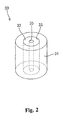
- Fig. 2 is a perspective view of the noise-reducing member in the connector of Fig. 1.
- Fig. 3 is a perspective view of another method of installing the noise-reducing member on a conductive wire.
- Fig. 4 is a sectional view showing a known connector described above.
-
- As shown in Fig. 1, the connector of the embodiment of the invention has a
housing 11 made of molded synthetic resin. Ahood part 12 in which a mating connector (not shown) is to be fitted in use is formed on the front side of thehousing 11. Aflat part 13 is formed on the rear side of thehousing 11. A pair of box-shaped mounting portions 14 are located at the lower end of the rear side of theflat part 13. Ascrew hole 14A is formed in eachmounting portion 14. Thehousing 11 can be secured to a substrate (not shown), e.g. a vehicle body by inserting screws into thescrew holes 14A, to fix the mountingportions 14 to the substrate. Thehousing 11 has five terminal press-fit holes 16 formed thereon. Each terminal press-fit hole 16 extends from the bottom surface of thehood part 12 to the rear surface of theflat part 13, with the terminal press-fit hole 16 penetrating through theflat part 13.Terminal fittings 20A - 20E are pressed into the terminal press-fit holes 16 respectively to penetrate therethrough. - Each of the
terminal fittings 20A - 20E is formed of conductive metal sheet. The conductive metal sheet is bent in the shape of an "L" at abend 21 to divide it into ahorizontal part 22 and avertical part 23. Theterminal fittings 20A - 20E have the same construction except that thehorizontal part 22 of each of theterminal fittings terminal fittings 20A - 20C. A tab (not shown) is formed at the front end of thehorizontal part 22. The tab projects into thehood part 12 and is connectable with a female terminal fitting (not shown) accommodated inside the mating connector which is fitted in thehood part 12. A projection (not shown) is formed widthwise at a base portion of the tab and pressed into the terminal press-fit hole 16 of thehousing 11. A part of thehorizontal part 22 projects from theflat part 13. Thevertical part 23 extends downward from thebend 21. The lower end portion of thevertical part 23 is formed as aconnection part 25 which has a smaller width than thevertical part 23 and which is connectable for example with a circuit mounted on a substrate (not shown). - An electrical noise-reducing
member 30 is installed selectively on any one of theterminal fittings 20A - 20E, according to need. In the embodiment, the noise-reducingmember 30 is installed on the terminal fitting 20C. As shown in Fig. 2, the noise-reducingmember 30 is cylindrical, in this case circularly cylindrical, and has a double construction. That is, the noise-reducingmember 30 has a body of noise-reducingmagnetic material 31 provided at the outer side thereof (to form an outer cylindrical portion), and an installingmaterial 32 provided at the inner side thereof (to form an inner cylindrical portion). The installingmaterial 32 is used to install the noise-reducingmember 30 on any one of theterminal fittings 20A - 20E. - The cylindrical
magnetic material body 31 is made of a ferromagnetic material such as ferrite and has a through-hole 33. Suitable magnetic materials for this purpose are known to the expert. The installingmaterial 32 is formed cylindrically by molding an elastic material such as a rubber and has an installing through-hole 35 at its centre. The installingmaterial 32 is fitted in the through-hole 33 by press-fitting. The inner diameter of the installing through-hole 35 is slightly smaller than the width of thevertical part 23 of each of theterminal fittings 20A - 20E. Thus, by inserting thevertical part 23 of any one of the terminal fittings 2.0A - 20E into the through-hole 35 by press fitting, the installingmaterial 32 is vertically slidable on thevertical part 23 and can be elastically locked to any one of theterminal fittings 20A -20E. - To assemble the
connector 10 of the embodiment, after thehousing 11 is formed by molding a suitable material, theterminal fittings 20A - 20E are inserted into the terminal press-fit holes 16 respectively by press fitting before bending them at thebend 21. Theterminal fittings 20A - 20E projecting rearward from thehousing 11 are bent downward at thebending position 21 with a jig. In this manner, a semi-finished molded product having thehousing 11 and theterminal fittings 20A - 20E mounted thereon is obtained. - Then, the electrical noise-reducing
member 30 is installed on any one (20C in the embodiment) of theterminal fittings 20A - 20E of the semi-finished molded product. First, theconnection part 25 of the terminal fitting 20C is inserted into the through-hole 35 of the installingmaterial 32. Then, the noise-reducingmember 30 is slid upward on thevertical part 23, and then stopped at an appropriate position. The installingmaterial 32 elastically grips thevertical part 23. Consequently, the noise-reducingmember 30 is fixed in its desired position on the terminal fitting 20C. - This completes the assembly of the
connector 10. If electric current flowing through the terminal fitting 20C includes a high-frequency noise during the use of theconnector 10, themagnetic material 31 absorbs the noise, achieving noise reduction. - In this embodiment, by inserting the terminal fitting 20C into the installing
material 32 of the noise-reducingmember 30, the installingmaterial 32 can be elastically locked to the terminal fitting 20C. That is, themagnetic material 31 can be installed on the terminal fitting 20C in a simple manner. In comparison with the known device of Fig. 4, this eliminates the need for forming the magnetic material integrally with the housing by insert molding or forming an elastically deformable lance integrally with the housing to lock the magnetic material to the housing. Therefore, the molding die for thehousing 11 can be simplified, which allows the manufacturing cost of the connector to be reduced. - Further, the installing
material 32 is made of elastic material such as rubber and is elastically locked to any one of theterminal fittings 20A - 20E inserted into the installinghole 35 by press fitting. Therefore, it is a straightforward process to install the noise-reducingmember 30 on any one of theterminal fittings 20A - 20E. - Further, the noise-reducing
member 30 is removably installed on any one of theterminal fittings 20A - 20E. Thus, for example, the noise-reducingmember 30 may be installed initially on any one of theterminal fittings 20A - 20E of thehousing 11. However, the noise-reducingmember 30 can then be transferred to any other of theterminal fittings 20A - 20E at a later stage of fabrication e.g. according to a specific noise-reducing requirement for the electrical circuit. The initial installation and later fabrication may occur at different sites, and transporting the noise-reducingmember 30 carried on a terminal fitting is more convenient than transporting the noise-reducing member separately from the housing between the sites. - A typical application of the invention is in a DC electrical circuit, such as in an automobile, e.g. in a radio power circuit.
- The scope of the present invention is not limited to the above-described embodiment, and the following embodiments for example are included in the scope of the present invention.
- (1) In the above-described embodiment, the present
invention is applicable to the
connector 10 which, in use, is installed on a substrate, but the noise-reducing member of the present invention is also applicable to other kinds of connectors. In addition, the noise-reducing member may be used for installing the magnetic material on an electrical wire, the wire passing through the centre of the noise-reducing member. The wire may be a bare wire or a wire having an insulating covering gripped by theinner portion 32. - (2) In the above-described embodiment, the
terminal fittings 20A - 20E are installed on thehousing 11 by press-fitting a part of each thereof into thehousing 11, but they may be installed on thehousing 11 by other methods. For example, they may be incorporated integrally with thehousing 11 by insert molding. - (3) In the above-described embodiment, one noise-reducing
member 30 is installed on one terminal fitting 20C. But within the present invention, a plurality of the noise-reducingmembers 30 may be installed on one connector. Further, a plurality of terminal fittings or other conductors may be secured to one electrical noise-reducing member by inserting the conductors thereinto; in this case, the body of magnetic material may have a plurality of through-holes each containing an elastically deformable member gripping the respective electrical conductor in the through-hole, or the body may have one through-hole having an elastically deformable member itself having plural through-holes gripping the respective electrical conductors. - (4) In the above-described embodiment, the noise-reducing
member 30 is installed on the terminal fitting 20C by a particular method, but the installing procedure is not limited to that described. For example, as shown in Fig. 3, the noise-reducing member may be formed in situ by inserting the terminal fitting 20C into the through-hole 33 of themagnetic material 31, the installingmaterial 32 being pre-mounted on the terminal fitting 20C and being pressed into the through-hole 33 during the insertion. -
- While the invention has been described in conjunction with the exemplary embodiments described above, many equivalent modifications and variations will be apparent to those skilled in the art when given this disclosure. Accordingly, the exemplary embodiments of the invention set forth above are considered to be illustrative and not limiting. Various changes to the described embodiments may be made without departing from the spirit and scope of the invention.
Claims (9)
- An electrical noise-reducing assembly comprising at least one elongate electrical conductor (20C) and an electrical noise-reducing member (30) carried on the electrical conductor, the noise-reducing member (30) comprising a body (31) of magnetic material having at least one through-hole, through which the electrical conductor (20C) extends, and an elastically deformable member (32) fixed in said through-hole and elastically gripping the electrical conductor therein so as to hold the body of magnetic material in position on the electrical conductor.
- An assembly according to claim 1, wherein said body (31) of magnetic material and said elastically deformable member (32) are both circularly cylindrical.
- An electrical noise-reducing assembly according to claim 1, having a plurality of said electrical conductors, wherein said body of magnetic material has a plurality of said through-holes through which said electrical conductors respectively extend, and a plurality of said elastically deformable members fixed respectively in said through-holes and electrically gripping said electrical conductors.
- An electrical noise-reducing assembly according to any one of claims 1 to 3, wherein said elastically deformable member (32) is made of rubber.
- An electrical noise-reducing member (30) comprising inner (32) and outer (31) cylindrical portions secured together, wherein said outer cylindrical portion is of electrical noise-reducing magnetic material, and said inner cylindrical portion (32) is of elastically deformable material and has a longitudinal through-hole (35) for elastically securing it to an elongate electrical conductive element (20C) which, in use, is inserted into said through-hole.
- A member according to claim 5, wherein said inner cylindrical portion (32) is of rubber.
- A member according to claim 5 or 6, which is secured to said electrically conductive element (20C) which extends through said through-hole (35) and is elastically gripped by said inner cylindrical portion (32).
- An electrical connector comprising said electrical noise-reducing member (30) and said conductive element (20C) of claim 7, said conductive element being a terminal of the connector.
- An electrical connector according to claim 8, having a body holding said terminal (20C), said noise-reducing member (30) being mounted on a portion of said terminal projecting from said body.
Applications Claiming Priority (2)
| Application Number | Priority Date | Filing Date | Title |
|---|---|---|---|
| JP2000091162A JP2001283990A (en) | 2000-03-29 | 2000-03-29 | Noise removing member and mounting structure of conductive wire and noise removing member |
| JP2000091162 | 2000-03-29 |
Publications (2)
| Publication Number | Publication Date |
|---|---|
| EP1139507A1 true EP1139507A1 (en) | 2001-10-04 |
| EP1139507B1 EP1139507B1 (en) | 2004-01-02 |
Family
ID=18606656
Family Applications (1)
| Application Number | Title | Priority Date | Filing Date |
|---|---|---|---|
| EP01302608A Expired - Lifetime EP1139507B1 (en) | 2000-03-29 | 2001-03-21 | Electrical noise-reducing assembly and member |
Country Status (5)
| Country | Link |
|---|---|
| US (1) | US6375510B2 (en) |
| EP (1) | EP1139507B1 (en) |
| JP (1) | JP2001283990A (en) |
| CN (1) | CN1320983A (en) |
| DE (1) | DE60101642T2 (en) |
Families Citing this family (65)
| Publication number | Priority date | Publication date | Assignee | Title |
|---|---|---|---|---|
| JP2001035808A (en) * | 1999-07-22 | 2001-02-09 | Semiconductor Energy Lab Co Ltd | Wiring, method of manufacturing the same, semiconductor device provided with the wiring, and dry etching method |
| DE19943045A1 (en) * | 1999-09-09 | 2001-04-05 | Pfisterer Kontaktsyst Gmbh | Device for connecting electrical conductors |
| US6623275B1 (en) * | 2002-06-28 | 2003-09-23 | Amphenol-Tuchel Electronics Gmbh | Filtered electrical connector with adjustable performance using combined multi-aperture ferrite cores |
| US7285018B2 (en) * | 2004-06-23 | 2007-10-23 | Amphenol Corporation | Electrical connector incorporating passive circuit elements |
| US20090291593A1 (en) | 2005-06-30 | 2009-11-26 | Prescott Atkinson | High frequency broadside-coupled electrical connector |
| JP4767830B2 (en) * | 2006-12-11 | 2011-09-07 | 株式会社オートネットワーク技術研究所 | Branch connector |
| CN102906947B (en) | 2009-11-13 | 2016-04-13 | 安费诺有限公司 | The connector controlled with normal mode reactance of high-performance, small-shape factor |
| EP2539971A4 (en) | 2010-02-24 | 2014-08-20 | Amphenol Corp | High bandwidth connector |
| CN107069274B (en) | 2010-05-07 | 2020-08-18 | 安费诺有限公司 | High performance cable connector |
| US20110287663A1 (en) | 2010-05-21 | 2011-11-24 | Gailus Mark W | Electrical connector incorporating circuit elements |
| US8382524B2 (en) | 2010-05-21 | 2013-02-26 | Amphenol Corporation | Electrical connector having thick film layers |
| WO2012106554A2 (en) | 2011-02-02 | 2012-08-09 | Amphenol Corporation | Mezzanine connector |
| WO2013059317A1 (en) | 2011-10-17 | 2013-04-25 | Amphenol Corporation | Electrical connector with hybrid shield |
| US8591257B2 (en) | 2011-11-17 | 2013-11-26 | Amphenol Corporation | Electrical connector having impedance matched intermediate connection points |
| CN108336593B (en) | 2012-06-29 | 2019-12-17 | 安费诺有限公司 | Low-cost high-performance radio frequency connector |
| WO2014031851A1 (en) | 2012-08-22 | 2014-02-27 | Amphenol Corporation | High-frequency electrical connector |
| WO2014160356A1 (en) | 2013-03-13 | 2014-10-02 | Amphenol Corporation | Housing for a speed electrical connector |
| US9484674B2 (en) | 2013-03-14 | 2016-11-01 | Amphenol Corporation | Differential electrical connector with improved skew control |
| CN121367083A (en) | 2014-01-22 | 2026-01-20 | 安费诺有限公司 | Electrical connector, sub-assembly, module, cable assembly, electrical assembly and circuit board |
| WO2015164538A1 (en) | 2014-04-23 | 2015-10-29 | Tyco Electronics Corporation | Electrical connector with shield cap and shielded terminals |
| US9472904B2 (en) | 2014-08-18 | 2016-10-18 | Amphenol Corporation | Discrete packaging adapter for connector |
| CN107112696B (en) | 2014-11-12 | 2020-06-09 | 安费诺有限公司 | Very high speed, high density electrical interconnect system with impedance control in the mating area |
| US10541482B2 (en) | 2015-07-07 | 2020-01-21 | Amphenol Fci Asia Pte. Ltd. | Electrical connector with cavity between terminals |
| CN108028481B (en) | 2015-07-23 | 2021-08-20 | 安费诺有限公司 | Extender Modules for Modular Connectors |
| CN109565137A (en) | 2016-05-31 | 2019-04-02 | 安费诺有限公司 | High-performance cable termination device |
| WO2017209694A1 (en) | 2016-06-01 | 2017-12-07 | Amphenol Fci Connectors Singapore Pte. Ltd. | High speed electrical connector |
| CN111755867B (en) | 2016-08-23 | 2022-09-20 | 安费诺有限公司 | Configurable high performance connector |
| CN115189188A (en) | 2016-10-19 | 2022-10-14 | 安费诺有限公司 | Flexible shielding piece, electric connector and electronic device |
| CN119209123A (en) | 2017-08-03 | 2024-12-27 | 安费诺有限公司 | Cable connectors for high-speed interconnects |
| WO2019084717A1 (en) | 2017-10-30 | 2019-05-09 | Amphenol Fci Asia Pte Ltd | Low crosstalk card edge connector |
| US10601181B2 (en) | 2017-12-01 | 2020-03-24 | Amphenol East Asia Ltd. | Compact electrical connector |
| US10777921B2 (en) | 2017-12-06 | 2020-09-15 | Amphenol East Asia Ltd. | High speed card edge connector |
| US10665973B2 (en) | 2018-03-22 | 2020-05-26 | Amphenol Corporation | High density electrical connector |
| WO2019195319A1 (en) | 2018-04-02 | 2019-10-10 | Ardent Concepts, Inc. | Controlled-impedance compliant cable termination |
| CN208862209U (en) | 2018-09-26 | 2019-05-14 | 安费诺东亚电子科技(深圳)有限公司 | A kind of connector and its pcb board of application |
| CN113169484A (en) | 2018-10-09 | 2021-07-23 | 安费诺商用电子产品(成都)有限公司 | High density edge connector |
| TWM576774U (en) | 2018-11-15 | 2019-04-11 | 香港商安費諾(東亞)有限公司 | Metal case with anti-displacement structure and connector thereof |
| US10931062B2 (en) | 2018-11-21 | 2021-02-23 | Amphenol Corporation | High-frequency electrical connector |
| US11381015B2 (en) | 2018-12-21 | 2022-07-05 | Amphenol East Asia Ltd. | Robust, miniaturized card edge connector |
| CN117175239A (en) | 2019-01-25 | 2023-12-05 | 富加宜(美国)有限责任公司 | Socket connectors and electrical connectors |
| WO2020154526A1 (en) | 2019-01-25 | 2020-07-30 | Fci Usa Llc | I/o connector configured for cabled connection to the midboard |
| US11189971B2 (en) | 2019-02-14 | 2021-11-30 | Amphenol East Asia Ltd. | Robust, high-frequency electrical connector |
| CN111585098B (en) | 2019-02-19 | 2025-08-19 | 安费诺有限公司 | High-speed connector |
| CN113728521B (en) | 2019-02-22 | 2025-03-18 | 安费诺有限公司 | High-performance cable connector assemblies |
| TWM582251U (en) | 2019-04-22 | 2019-08-11 | 香港商安費諾(東亞)有限公司 | Connector set with hidden locking mechanism and socket connector thereof |
| CN114128053B (en) | 2019-05-20 | 2024-10-11 | 安费诺有限公司 | High-density and high-speed electrical connectors |
| CN114788097A (en) | 2019-09-19 | 2022-07-22 | 安费诺有限公司 | High speed electronic system with midplane cable connector |
| US11588277B2 (en) | 2019-11-06 | 2023-02-21 | Amphenol East Asia Ltd. | High-frequency electrical connector with lossy member |
| US11799230B2 (en) | 2019-11-06 | 2023-10-24 | Amphenol East Asia Ltd. | High-frequency electrical connector with in interlocking segments |
| WO2021154718A1 (en) | 2020-01-27 | 2021-08-05 | Fci Usa Llc | High speed, high density direct mate orthogonal connector |
| CN115428275B (en) | 2020-01-27 | 2025-12-30 | 富加宜(美国)有限责任公司 | High-speed connector |
| CN113258325A (en) | 2020-01-28 | 2021-08-13 | 富加宜(美国)有限责任公司 | High-frequency middle plate connector |
| TWM625349U (en) | 2020-03-13 | 2022-04-11 | 大陸商安費諾商用電子產品(成都)有限公司 | Reinforcing member, electrical connector, circuit board assembly and insulating body |
| US11728585B2 (en) | 2020-06-17 | 2023-08-15 | Amphenol East Asia Ltd. | Compact electrical connector with shell bounding spaces for receiving mating protrusions |
| US11831092B2 (en) | 2020-07-28 | 2023-11-28 | Amphenol East Asia Ltd. | Compact electrical connector |
| US11652307B2 (en) | 2020-08-20 | 2023-05-16 | Amphenol East Asia Electronic Technology (Shenzhen) Co., Ltd. | High speed connector |
| CN212874843U (en) | 2020-08-31 | 2021-04-02 | 安费诺商用电子产品(成都)有限公司 | electrical connector |
| CN215816516U (en) | 2020-09-22 | 2022-02-11 | 安费诺商用电子产品(成都)有限公司 | Electrical connector |
| CN213636403U (en) | 2020-09-25 | 2021-07-06 | 安费诺商用电子产品(成都)有限公司 | Electrical connector |
| US11569613B2 (en) | 2021-04-19 | 2023-01-31 | Amphenol East Asia Ltd. | Electrical connector having symmetrical docking holes |
| US12176650B2 (en) | 2021-05-05 | 2024-12-24 | Amphenol East Asia Limited (Hong Kong) | Electrical connector with guiding structure and mating groove and method of connecting electrical connector |
| CN215266741U (en) | 2021-08-13 | 2021-12-21 | 安费诺商用电子产品(成都)有限公司 | High-performance card connector meeting high-bandwidth transmission |
| USD1002553S1 (en) | 2021-11-03 | 2023-10-24 | Amphenol Corporation | Gasket for connector |
| USD1068685S1 (en) | 2021-12-14 | 2025-04-01 | Amphenol Corporation | Electrical connector |
| USD1067191S1 (en) | 2021-12-14 | 2025-03-18 | Amphenol Corporation | Electrical connector |
Citations (4)
| Publication number | Priority date | Publication date | Assignee | Title |
|---|---|---|---|---|
| US3702422A (en) * | 1971-06-10 | 1972-11-07 | Amp Inc | Filters for interconnection systems |
| EP0398807A2 (en) * | 1989-05-18 | 1990-11-22 | Amphenol Corporation | Stress isolated planar filter design |
| JPH0357176A (en) * | 1989-07-26 | 1991-03-12 | Moji:Kk | Cord disloation stopping device for connector |
| US5022870A (en) * | 1989-02-28 | 1991-06-11 | Murata Manufacturing Co., Ltd. | Retainer for connector terminals |
Family Cites Families (9)
| Publication number | Priority date | Publication date | Assignee | Title |
|---|---|---|---|---|
| US4126370A (en) * | 1977-06-17 | 1978-11-21 | Bunker Ramo Corporation | Filter connector with radial mounting means |
| US4276523A (en) * | 1979-08-17 | 1981-06-30 | Bunker Ramo Corporation | High density filter connector |
| US4458220A (en) * | 1981-07-17 | 1984-07-03 | Automation Industries, Inc. | Electrical connector and filter circuit |
| JPS58107614U (en) * | 1982-01-18 | 1983-07-22 | 株式会社村田製作所 | noise filter |
| US4820174A (en) * | 1986-08-06 | 1989-04-11 | Amp Incorporated | Modular connector assembly and filtered insert therefor |
| US4753611A (en) * | 1987-03-31 | 1988-06-28 | Amp Incorporated | Filtered coaxial assembly |
| EP0777325A3 (en) * | 1995-11-29 | 1998-01-14 | Mita Industrial Co. Ltd. | Grounding device for use in an image forming machine |
| JP3451946B2 (en) | 1998-07-03 | 2003-09-29 | 住友電装株式会社 | connector |
| US6059608A (en) * | 1999-01-21 | 2000-05-09 | Molex Incorporated | Filtered electrical connector with terminal tail aligner |
-
2000
- 2000-03-29 JP JP2000091162A patent/JP2001283990A/en active Pending
-
2001
- 2001-03-21 DE DE2001601642 patent/DE60101642T2/en not_active Expired - Lifetime
- 2001-03-21 EP EP01302608A patent/EP1139507B1/en not_active Expired - Lifetime
- 2001-03-28 CN CN01110164A patent/CN1320983A/en active Pending
- 2001-03-29 US US09/819,689 patent/US6375510B2/en not_active Expired - Lifetime
Patent Citations (4)
| Publication number | Priority date | Publication date | Assignee | Title |
|---|---|---|---|---|
| US3702422A (en) * | 1971-06-10 | 1972-11-07 | Amp Inc | Filters for interconnection systems |
| US5022870A (en) * | 1989-02-28 | 1991-06-11 | Murata Manufacturing Co., Ltd. | Retainer for connector terminals |
| EP0398807A2 (en) * | 1989-05-18 | 1990-11-22 | Amphenol Corporation | Stress isolated planar filter design |
| JPH0357176A (en) * | 1989-07-26 | 1991-03-12 | Moji:Kk | Cord disloation stopping device for connector |
Non-Patent Citations (1)
| Title |
|---|
| PATENT ABSTRACTS OF JAPAN vol. 015, no. 204 (E - 1071) 24 May 1991 (1991-05-24) * |
Also Published As
| Publication number | Publication date |
|---|---|
| US6375510B2 (en) | 2002-04-23 |
| DE60101642D1 (en) | 2004-02-05 |
| JP2001283990A (en) | 2001-10-12 |
| US20010027061A1 (en) | 2001-10-04 |
| CN1320983A (en) | 2001-11-07 |
| EP1139507B1 (en) | 2004-01-02 |
| DE60101642T2 (en) | 2004-11-18 |
Similar Documents
| Publication | Publication Date | Title |
|---|---|---|
| US6375510B2 (en) | Electrical noise-reducing assembly and member | |
| US7597563B2 (en) | Conducting member and connector having conducting member | |
| EP0945937A2 (en) | Electrical terminal | |
| US6042431A (en) | Joint device for an automotive wiring harness | |
| EP0969568A1 (en) | A connector and method for producing the same | |
| JP2002509650A (en) | Circuit board mount | |
| JP4729307B2 (en) | Circuit board connector having an integral dielectric cover | |
| US5711676A (en) | Vertically mounted cable plug | |
| US7755232B2 (en) | DC motor with suppressor | |
| US6437268B1 (en) | Circuit breaker terminal connector | |
| US5697813A (en) | Connection terminal | |
| US7468705B2 (en) | Anti-resonant circuit arrangement | |
| EP1139506B1 (en) | Electrical connector | |
| US6688922B2 (en) | Plug connector | |
| US7491087B2 (en) | Right angled connector | |
| US7289081B2 (en) | Antenna coil device | |
| KR100765653B1 (en) | Automotive Glass Antenna Jack | |
| US7708591B2 (en) | Shield connector | |
| EP1427065A1 (en) | Antenna cord plug structure | |
| JP2005149934A (en) | Joint connector | |
| JPH08330835A (en) | Automotive glass antenna receptacle and plug | |
| EP1566862A1 (en) | Right angled connector | |
| JP2002117949A (en) | Mounting equipment for high frequency coaxial connectors | |
| JP3685435B2 (en) | Television wiring equipment | |
| JPH0433658Y2 (en) |
Legal Events
| Date | Code | Title | Description |
|---|---|---|---|
| PUAI | Public reference made under article 153(3) epc to a published international application that has entered the european phase |
Free format text: ORIGINAL CODE: 0009012 |
|
| 17P | Request for examination filed |
Effective date: 20010410 |
|
| AK | Designated contracting states |
Kind code of ref document: A1 Designated state(s): AT BE CH CY DE DK ES FI FR GB GR IE IT LI LU MC NL PT SE TR Kind code of ref document: A1 Designated state(s): DE FR IT |
|
| AX | Request for extension of the european patent |
Free format text: AL;LT;LV;MK;RO;SI |
|
| 17Q | First examination report despatched |
Effective date: 20020423 |
|
| AKX | Designation fees paid |
Free format text: DE FR IT |
|
| GRAH | Despatch of communication of intention to grant a patent |
Free format text: ORIGINAL CODE: EPIDOS IGRA |
|
| GRAS | Grant fee paid |
Free format text: ORIGINAL CODE: EPIDOSNIGR3 |
|
| RBV | Designated contracting states (corrected) |
Designated state(s): DE FR |
|
| GRAA | (expected) grant |
Free format text: ORIGINAL CODE: 0009210 |
|
| AK | Designated contracting states |
Kind code of ref document: B1 Designated state(s): DE FR |
|
| REF | Corresponds to: |
Ref document number: 60101642 Country of ref document: DE Date of ref document: 20040205 Kind code of ref document: P |
|
| PLBE | No opposition filed within time limit |
Free format text: ORIGINAL CODE: 0009261 |
|
| STAA | Information on the status of an ep patent application or granted ep patent |
Free format text: STATUS: NO OPPOSITION FILED WITHIN TIME LIMIT |
|
| 26N | No opposition filed |
Effective date: 20041005 |
|
| EN | Fr: translation not filed | ||
| REG | Reference to a national code |
Ref country code: FR Ref legal event code: RN |
|
| REG | Reference to a national code |
Ref country code: FR Ref legal event code: FC |
|
| ET | Fr: translation filed | ||
| REG | Reference to a national code |
Ref country code: FR Ref legal event code: ST |
|
| REG | Reference to a national code |
Ref country code: FR Ref legal event code: FC |
|
| PGFP | Annual fee paid to national office [announced via postgrant information from national office to epo] |
Ref country code: FR Payment date: 20100408 Year of fee payment: 10 |
|
| PGFP | Annual fee paid to national office [announced via postgrant information from national office to epo] |
Ref country code: DE Payment date: 20100422 Year of fee payment: 10 |
|
| REG | Reference to a national code |
Ref country code: FR Ref legal event code: ST Effective date: 20111130 |
|
| PG25 | Lapsed in a contracting state [announced via postgrant information from national office to epo] |
Ref country code: FR Free format text: LAPSE BECAUSE OF NON-PAYMENT OF DUE FEES Effective date: 20110331 Ref country code: DE Free format text: LAPSE BECAUSE OF NON-PAYMENT OF DUE FEES Effective date: 20111001 |
|
| REG | Reference to a national code |
Ref country code: DE Ref legal event code: R119 Ref document number: 60101642 Country of ref document: DE Effective date: 20111001 |