EP1139457A2 - Nonaqueous electrolyte battery and production method thereof - Google Patents
Nonaqueous electrolyte battery and production method thereof Download PDFInfo
- Publication number
- EP1139457A2 EP1139457A2 EP01103320A EP01103320A EP1139457A2 EP 1139457 A2 EP1139457 A2 EP 1139457A2 EP 01103320 A EP01103320 A EP 01103320A EP 01103320 A EP01103320 A EP 01103320A EP 1139457 A2 EP1139457 A2 EP 1139457A2
- Authority
- EP
- European Patent Office
- Prior art keywords
- nonaqueous electrolyte
- lid body
- electrolyte battery
- container
- metal plate
- Prior art date
- Legal status (The legal status is an assumption and is not a legal conclusion. Google has not performed a legal analysis and makes no representation as to the accuracy of the status listed.)
- Withdrawn
Links
Images


Classifications
-
- H—ELECTRICITY
- H01—ELECTRIC ELEMENTS
- H01M—PROCESSES OR MEANS, e.g. BATTERIES, FOR THE DIRECT CONVERSION OF CHEMICAL ENERGY INTO ELECTRICAL ENERGY
- H01M50/00—Constructional details or processes of manufacture of the non-active parts of electrochemical cells other than fuel cells, e.g. hybrid cells
- H01M50/10—Primary casings; Jackets or wrappings
- H01M50/147—Lids or covers
- H01M50/166—Lids or covers characterised by the methods of assembling casings with lids
- H01M50/171—Lids or covers characterised by the methods of assembling casings with lids using adhesives or sealing agents
-
- H—ELECTRICITY
- H01—ELECTRIC ELEMENTS
- H01M—PROCESSES OR MEANS, e.g. BATTERIES, FOR THE DIRECT CONVERSION OF CHEMICAL ENERGY INTO ELECTRICAL ENERGY
- H01M50/00—Constructional details or processes of manufacture of the non-active parts of electrochemical cells other than fuel cells, e.g. hybrid cells
- H01M50/10—Primary casings; Jackets or wrappings
- H01M50/147—Lids or covers
- H01M50/166—Lids or covers characterised by the methods of assembling casings with lids
- H01M50/169—Lids or covers characterised by the methods of assembling casings with lids by welding, brazing or soldering
-
- H—ELECTRICITY
- H01—ELECTRIC ELEMENTS
- H01M—PROCESSES OR MEANS, e.g. BATTERIES, FOR THE DIRECT CONVERSION OF CHEMICAL ENERGY INTO ELECTRICAL ENERGY
- H01M50/00—Constructional details or processes of manufacture of the non-active parts of electrochemical cells other than fuel cells, e.g. hybrid cells
- H01M50/30—Arrangements for facilitating escape of gases
- H01M50/342—Non-re-sealable arrangements
-
- H—ELECTRICITY
- H01—ELECTRIC ELEMENTS
- H01M—PROCESSES OR MEANS, e.g. BATTERIES, FOR THE DIRECT CONVERSION OF CHEMICAL ENERGY INTO ELECTRICAL ENERGY
- H01M10/00—Secondary cells; Manufacture thereof
- H01M10/05—Accumulators with non-aqueous electrolyte
- H01M10/052—Li-accumulators
- H01M10/0525—Rocking-chair batteries, i.e. batteries with lithium insertion or intercalation in both electrodes; Lithium-ion batteries
-
- H—ELECTRICITY
- H01—ELECTRIC ELEMENTS
- H01M—PROCESSES OR MEANS, e.g. BATTERIES, FOR THE DIRECT CONVERSION OF CHEMICAL ENERGY INTO ELECTRICAL ENERGY
- H01M50/00—Constructional details or processes of manufacture of the non-active parts of electrochemical cells other than fuel cells, e.g. hybrid cells
- H01M50/10—Primary casings; Jackets or wrappings
- H01M50/102—Primary casings; Jackets or wrappings characterised by their shape or physical structure
- H01M50/107—Primary casings; Jackets or wrappings characterised by their shape or physical structure having curved cross-section, e.g. round or elliptic
-
- H—ELECTRICITY
- H01—ELECTRIC ELEMENTS
- H01M—PROCESSES OR MEANS, e.g. BATTERIES, FOR THE DIRECT CONVERSION OF CHEMICAL ENERGY INTO ELECTRICAL ENERGY
- H01M50/00—Constructional details or processes of manufacture of the non-active parts of electrochemical cells other than fuel cells, e.g. hybrid cells
- H01M50/30—Arrangements for facilitating escape of gases
- H01M50/342—Non-re-sealable arrangements
- H01M50/3425—Non-re-sealable arrangements in the form of rupturable membranes or weakened parts, e.g. pierced with the aid of a sharp member
-
- Y—GENERAL TAGGING OF NEW TECHNOLOGICAL DEVELOPMENTS; GENERAL TAGGING OF CROSS-SECTIONAL TECHNOLOGIES SPANNING OVER SEVERAL SECTIONS OF THE IPC; TECHNICAL SUBJECTS COVERED BY FORMER USPC CROSS-REFERENCE ART COLLECTIONS [XRACs] AND DIGESTS
- Y02—TECHNOLOGIES OR APPLICATIONS FOR MITIGATION OR ADAPTATION AGAINST CLIMATE CHANGE
- Y02E—REDUCTION OF GREENHOUSE GAS [GHG] EMISSIONS, RELATED TO ENERGY GENERATION, TRANSMISSION OR DISTRIBUTION
- Y02E60/00—Enabling technologies; Technologies with a potential or indirect contribution to GHG emissions mitigation
- Y02E60/10—Energy storage using batteries
-
- Y—GENERAL TAGGING OF NEW TECHNOLOGICAL DEVELOPMENTS; GENERAL TAGGING OF CROSS-SECTIONAL TECHNOLOGIES SPANNING OVER SEVERAL SECTIONS OF THE IPC; TECHNICAL SUBJECTS COVERED BY FORMER USPC CROSS-REFERENCE ART COLLECTIONS [XRACs] AND DIGESTS
- Y02—TECHNOLOGIES OR APPLICATIONS FOR MITIGATION OR ADAPTATION AGAINST CLIMATE CHANGE
- Y02P—CLIMATE CHANGE MITIGATION TECHNOLOGIES IN THE PRODUCTION OR PROCESSING OF GOODS
- Y02P70/00—Climate change mitigation technologies in the production process for final industrial or consumer products
- Y02P70/50—Manufacturing or production processes characterised by the final manufactured product
-
- Y—GENERAL TAGGING OF NEW TECHNOLOGICAL DEVELOPMENTS; GENERAL TAGGING OF CROSS-SECTIONAL TECHNOLOGIES SPANNING OVER SEVERAL SECTIONS OF THE IPC; TECHNICAL SUBJECTS COVERED BY FORMER USPC CROSS-REFERENCE ART COLLECTIONS [XRACs] AND DIGESTS
- Y10—TECHNICAL SUBJECTS COVERED BY FORMER USPC
- Y10T—TECHNICAL SUBJECTS COVERED BY FORMER US CLASSIFICATION
- Y10T29/00—Metal working
- Y10T29/49—Method of mechanical manufacture
- Y10T29/49002—Electrical device making
- Y10T29/49108—Electric battery cell making
Definitions
- the present invention relates to a nonaqueous electrolyte battery including a container sealed with a sealing lid, and a method of producing the nonaqueous electrolyte battery.
- an electrolytic solution for a lithium or lithium ion battery there has been used a solution obtained by dissolving an electrolyte exemplified by a lithium based electrolyte salt such as LiPF 6 in a nonaqueous solvent exemplified by a carbonate such as low molecular ethylene carbonate, propylene carbonate, or diethyl carbonate. This is because such an electrolytic solution has a relatively high conductivity and exhibits a stable potential.
- a lithium based electrolyte salt such as LiPF 6
- a carbonate such as low molecular ethylene carbonate, propylene carbonate, or diethyl carbonate.
- an electrolytic solution contains an organic solvent as described above, and accordingly, when wiring of the battery is short-circuited or the battery is abnormally heated for example, the electrolytic solution may be vaporized and decomposed to generate gas. If the generation rate of such a gas becomes a specific value or more, an inner pressure of an enclosed container may be rapidly raised.
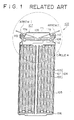
- the nonaqueous electrolyte battery 100 includes an electrode body 104 formed by spirally winding a stack of a positive electrode 101, a separator 102, and a negative electrode 103; a container 105 for containing the electrode body 104; an insulating plate 106 disposed on a bottom portion of the container 105, for preventing the electrode body 104 from being brought into electric contact with the container 105; and a sealing lid group 107 fixed by caulking to an opening at the upper end of the container 105 via an insulating gasket 113.
- the sealing lid group 107 includes a disk-like inner lid body 108 disposed opposite to the electrode body 104; a PTC element 110 disposed on an ring portion of the inner lid body 108 via a valve film 109 formed of a flexible thin film; and a cap-shaped battery lid 111 disposed with its peripheral edge being in contact with the PTC element 110.
- Each of the inner lid body 108 and the PTC element 110 has at its central portion a though-hole, and the battery lid 111 has at its stepped portion vent holes llla.
- One end of a positive electrode lead 112 is connected to the positive electrode 101 of the electrode body 104, and the other end thereof is connected to a back surface of the inner lid body 108 of the sealing lid group 7.
- the resistance of the PTC element 110 positioned between the inner lid 108 and the battery lid 111 is rapidly increased with temperature rise, to stop the supply of current, thereby preventing an increase in inner pressure in the nonaqueous electrolyte battery 100.
- a decomposition gas is generated and thereby the inner pressure in the nonaqueous electrolyte battery 100 reaches a specific pressure, the decomposition gas passes through the though-hole opened in the inner lid body 108, to break or melt the valve film 109 positioned over the inner lid body 108.
- the decomposition gas is discharged to the outside of the nonaqueous electrolyte battery 100 through the broken portion of the valve film 109, the through-hole opened in the PTC element 110, and the vent holes llla opened in the battery lid 111, to thereby reduce the inner pressure in the nonaqueous electrolyte battery 100.
- part of the decomposition gas discharged from the broken portion of the valve film 109 is directly discharged to the outside of the nonaqueous electrolyte battery 100 through the vent holes llla of the battery lid 111 without collision with the inner side of the battery lid 111.
- the part of the decomposition gas, which directly passes through the vent holes llla, is discharged obliquely with respect to the height direction of the nonaqueous electrolyte battery 100, to thereby give a motive force to the nonaqueous electrolyte battery 100.
- FIG. 2 is an enlarged view showing a circle portion H in FIG. 1.
- part of the decomposition gas once collides with the inner side of a projecting portion of the battery lid 111 as shown by an arrow J, and is discharged from the vent holes 111a along the direction substantially perpendicular to the height direction of the nonaqueous electrolyte battery 100 as shown by arrows K.
- Part of the decomposition gas discharged in such a direction collides with a caulking portion formed by inwardly bending an opening edge of the container 105, and flows in the height direction of the nonaqueous electrolyte battery 100 as shown by arrows L.
- the nonaqueous electrolyte battery 100 is moved by a motive force generated by the discharge of the decomposition gas, to exert adverse effect on peripheral equipment. Further, the decomposition gas having broken the valve film 109 is discharged from the vent holes llla at a high speed, whereby the motive force given to the nonaqueous electrolyte battery 100 becomes larger. As a result, there arises a problem that the movement of the nonaqueous electrolyte battery 100 by the discharge of the decomposition gas becomes larger.
- An object of the present invention is to provide a nonaqueous electrolyte battery capable of preventing the movement of the nonaqueous electrolyte battery by a motive force generated by discharge of a decomposition gas generated in an abnormal state, and a method of producing the nonaqueous electrolyte battery.
- a nonaqueous electrolyte battery including: an electrode body having at least a positive electrode and a negative electrode; a cylindrical container with its bottom closed, in which the electrode body and a nonaqueous electrolytic solution are contained; and a lid body for closing an opening portion of the container; wherein the lid body has a lid portion which constitutes a peripheral edge portion of the lid body, a projecting portion which constitutes a central portion of the lid body, and a stepped portion which has a vent hole and is positioned between the lid portion and the projecting portion; and a metal plate having a through-hole is disposed between the lid body and the electrode body.
- a nonaqueous electrolyte battery including: an electrode body having at least a positive electrode and a negative electrode; a cylindrical container with its bottom closed, in which the electrode body and a nonaqueous electrolytic solution are contained; and a lid body for closing an opening portion of the container; wherein the lid body has a lid portion which constitutes a peripheral edge portion of the lid body, a projecting portion which constitutes a central portion of the lid body, and a stepped portion which has a vent hole and is positioned between the lid portion and the projecting portion; and the projecting portion is formed into an approximately circular shape, and is substantially flattened; and letting a diameter of the substantially flattened portion be A and an outside diameter of the container be C, C and A satisfy a relationship of 0.55 ⁇ A/C ⁇ 1.
- a nonaqueous electrolyte battery including: an electrode body having at least a positive electrode and a negative electrode; a cylindrical container with its bottom closed, in which the electrode body and a nonaqueous electrolytic solution are contained; and a lid body for closing an opening portion of the container; wherein the lid body has a lid portion which constitutes a peripheral edge portion of the lid body, a projecting portion which constitutes a central portion of the lid body, and a stepped portion which has a vent hole and is positioned between the lid portion and the projecting portion; the lid body is held by a caulking portion formed by inwardly bending an outer peripheral edge of an opening portion of the container; a height of an end portion, on the projecting portion side, of the vent hole is intermediate between the top of the caulking portion and the projecting portion; and letting a difference in height between the top of the caulking portion and the end portion, on the projecting portion side, of the vent hole be D, and the
- the flow direction of the decomposition gas discharged from the vent hole of the lid body is not blocked by the caulking portion.
- the decomposition gas flows along the direction substantially perpendicular to the height direction of the battery.
- a method of producing a nonaqueous electrolyte battery including the steps of: putting an electrode body having at least a positive electrode and a negative electrode in a cylindrical container with its bottom closed; pouring a nonaqueous electrolytic solution in the container; disposing a metal plate having a through-hole over the electrode body; and placing a lid body on the metal plate in such a manner that an opening portion of the container is closed with the lid body, the lid body having a lid portion which constitutes a peripheral edge portion of the lid body, a projecting portion which constitutes a central portion of the lid body, and a stepped portion which has a vent hole and is positioned between the lid portion and the projecting portion.
- FIG. 3 shows a first embodiment of a nonaqueous electrolyte battery of the present invention.
- a nonaqueous electrolyte battery 1 includes an electrode body 5 formed by spirally winding a stack of a positive electrode 2, a separator 3, and a negative electrode 4; a container 6 for containing the electrode body 5; a sealing lid group 8 fixed by caulking to an opening portion at an upper end of the container 6 via an insulating gasket 7; and an electrolytic solution enclosed in the container 6.
- One end of a negative electrode lead 9 is electrically connected to the negative electrode 4, and the other end thereof is electrically connected to the container 6.
- a bottom insulator 10 having at its central portion a hole is disposed on a bottom portion of the container 6 for preventing the electrode body 5 from being brought into electric contact with the container 6.
- a top insulator 11 is disposed on an upper portion of the electrode body 5 for preventing the electrode body 5 from being brought into electric contact with the sealing lid group 8.
- the sealing lid group 8 includes a dish-like inner lid body 12 disposed opposite to the electrode body 5; a valve film 13 formed of a flexible thin film disposed on the inner lid body 12; a PTC element 14 disposed on the valve film 13; and an outer lid body 15 disposed with its peripheral edge portion being in contact with the PTC element 14.
- Each of the inner lid body 12 and the PTC element 14 has at its approximately central portion one or more through-holes.
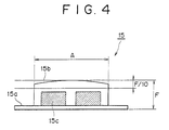
- the outer lid body 15 includes a lid portion 15a which constitutes a peripheral edge portion of the lid body 15, a projecting portion 15b which constitutes a central portion of the lid body 15, and a stepped portion positioned between the lid portion 15a and the projecting portion 15b.
- the stepped portion has a plurality of vent holes 15c disposed in an axial symmetric relation with respect to the center of the outer lid body 15.
- One end of a positive electrode lead 16 is connected to the positive electrode 2 of the electrode body 5 and the other end thereof is connected to a back surface of the inner lid body 12 of the sealing lid group 8.
- a center pin 17 made from a metal such as stainless steel or a plastic material can be disposed in a winding core space of the electrode body 5 in order to prevent the collapse of the winding core space and hence to ensure a flow path of a decomposition gas.
- a metal plate 18 having a though-hole is disposed between the outer lid body 15 and the electrode body 5, and more specifically, positioned typically between the PTC element 14 and the outer lid body 15.
- the center of the through-hole of the metal plate 18 is set to substantially correspond to the centers of the thin film portion of the valve film 13 and the through-hole of the PTC element 14.
- the decomposition gas having passed the through-hole of the inner lid body 12 first impinges on the inner side of the valve film 13 to break or melt the valve film 13.
- the decomposition gas having passed through the valve film 13 passes through the though-hole of the PTC element 14 and then passes through the through-hole of the metal plate 18.
- the decomposition gas is discharged to the outside of the battery 1 through the vent holes 15c formed in the outer lid body 15, whereby the inner pressure in the battery 1 is reduced, to thereby prevent the battery 1 from being damaged due to a rapid increase in inner pressure of the battery 1.
- the flow of the decomposition gas is suitably restricted in the radial direction. Accordingly, the decomposition gas having passed through the through-hole of the metal plate 18 once collides with the inner side of the projecting portion 15b of the outer lid body 15 as shown by an arrow M, and is discharged from the vent holes 15c provided in the stepped portion of the outer lid body 15 in the direction substantially perpendicular to the height direction of the battery 1 as shown by arrows N. As a result, the discharge speed of the decomposition gas is sufficiently damped, and the discharge direction of the decomposition gas becomes substantially perpendicular to the height direction of the battery 1.
- the plurality of vent holes 15c are disposed in an axial symmetric manner with respect to the center of the outer lid body 15 as described above, discharge vectors of parts of the decomposition gas discharged symmetrically with respect to the axis of the battery 1 cancel each other out. That is, the motive forces given to the battery 1 are substantially cancel each other out. In this way, the discharge of the decomposition gas can be certainly controlled such that the battery 1 is prevented from being moved by the motive force generated by the discharge of the decomposition gas.
- the through-hole of the metal plate 18 is formed into an approximately circular shape, and the projecting portion 15b of the outer lid body 15 is substantially flattened. Letting the diameter of the substantially flattened portion be A and the diameter of the through-hole of the metal plate 18 be B, B and A preferably satisfy a relationship of 0.2 ⁇ B/A ⁇ 0.8.
- the substantially flattened portion of the outer lid body 15 is defined as a portion having a height of less than F/10 from the uppermost end of the outer lid body 15.
- B/A is more than 0.8, that is, the through-hole of the metal plate 18 is excessively wider than the projecting portion 15b of the outer lid body 15, most of the decomposition gas having passed through the through-hole of the metal plate 18 is directly discharged from the vent holes 15c of the outer lid body 15 without collision with the inner side of the projecting portion 15b of the outer lid body 15.
- the discharge speed of the decomposition gas is not sufficiently damped and thereby a motive force is given to the battery 1, with a result that the battery 1 may be moved by the motive force.
- the metal plate 18 is preferably made from a material not melted by the decomposition gas at a high temperature, for example, a metal material such as iron or stainless steel. If the metal plate 18 is made from a material liable to be melted by the decomposition gas, the size of the through-hole of the metal plate 18 is changed by melting, with a result that there may occur an inconvenience that the discharge direction and the discharge speed of the decomposition gas cannot be controlled.
- the thickness of the metal plate 18 is preferably set to be in a range of 0.1 mm to 1 mm. When the thickness of the metal plate 18 is in the above range, it is possible to prevent the movement of the battery 1 due to discharge of the decomposition gas while keeping the battery capacity. If the thickness of the metal plate 18 is less than 0.1 mm, the strength of the metal plate 18 may be not enough to control the discharge direction and the discharge speed of the decomposition gas. On the other hand, if the thickness of the metal plate 18 is more than 1 mm, since the volume of the electrode body 5 contained in the container 6 becomes small, the battery capacity may be reduced.
- the metal plate 18 can be subjected to rust-preventive treatment.
- the metal plate 18 may be stuck on the PTC element 14 to be used as one part.
- the negative electrode 4 is produced by coating a negative collector with a negative mix containing a negative active material and a binder, and drying the negative mix, to form a negative active material layer on the negative collector.
- the negative collector is typically formed of a metal foil such as a copper foil.
- the negative electrode 4 is preferably made from lithium, a lithium alloy such as lithium-aluminum alloy, or a material to or from which lithium can be doped or released.
- a lithium alloy such as lithium-aluminum alloy
- a material to or from which lithium can be doped or released there can be used a carbon material such as a difficult-to-graphitize carbon based material or a graphite based material.
- these carbon materials may include pyrolytic carbons, cokes such as pitch coke, needle coke, and petroleum coke, graphites, vitreous carbon fibers, sintered organic high polymer compounds, carbon fibers, and activated charcoals.
- the sintered organic high polymer compound is produced by sintering phenol resin or furan resin at a suitable temperature, thereby carbonizing the resin.
- a high polymer such as polyacetylene or polypyrrole, or an oxide such as SnO 2 can be used as the material to or from which lithium can be doped or released.
- binder of the above negative mix there can be used a known binder, which has been used for a negative mix for a general lithium ion battery. Further, known additives can be added to the negative mix.
- the positive electrode 2 is produced by coating a positive collector with a positive mix containing a positive active material and a binder, and drying the positive mix, to form a positive active material layer on the positive collector.
- the positive collector is typically formed of a metal foil such as an aluminum foil.
- a metal oxide, a metal sulfide, or a specific high polymer can be used depending on the kind of the battery used.
- TiS 2 , MnO 2 , graphite, or FeS 2 can be used as the positive active material.
- a metal sulfide such as TiS 2 , MoS 2 , or NbSe 2 , or a metal oxide such as V 2 O 5 can be used as the positive active material.
- a transition metal oxide containing lithium which is typically expressed by a chemical formula LiM x O 2 where M is one or more kinds of transition metals and x is a value depending on a charging/discharging state of the battery and usually set in a range of 0.05 to 1.10, can be also used as the positive active material.
- the transition metals M of the transition metal oxide containing lithium are represented by Co, Ni, and Mn.
- Specific examples of the transition metal oxide containing lithium may include LiCoO 2 , LiNiO 2 , LiNi y Co 1-y O 2 (0 ⁇ y ⁇ 1), and LiMn 2 O 4 .
- Such a transition metal oxide containing lithium is used as the positive active material capable of generating a high voltage and ensuring a high energy density.
- an oxide of manganese or a composite oxide of lithium and manganese having a spinel type crystal structure is preferably used as the positive active material.
- the above-described positive active materials may be used for the positive electrode 2 singly or in combination.
- binder of the above positive mix there can be used a known binder, which has been used for a positive mix for a general battery. Further, known additives can be added to the positive mix.
- the separator 3 is disposed between the positive electrode 2 and the negative electrode 4 for preventing the positive electrode 2 and the negative electrode 4 from being short-circuited by physical contact therebetween.
- a microporous polyolefine film such as a polyethylene film or polypropylene film having pores, can be used as the separator 3.
- the electrolytic solution is prepared by dissolving an electrolyte salt in a nonaqueous solvent.
- the electrolyte salt there can be used a known electrolyte salt, which has been generally used as an electrolytic solution for a battery.
- the electrolyte salts may include lithium salts such as LiPF 6 , LiBF 4 , LiAsF 6 , LiClO 4 , LiCF 3 SO 3 , LiN (SO 2 CF 3 ) 2 , LiC(SO 2 CF 3 ) 3 , LiAlCl 4 , and LiSiF6.
- LiPF 6 and LiBF 4 are desirable from the viewpoint of stability against oxidation.
- the electrolyte salt is dissolved in a nonaqueous solvent at a concentration of, preferably, 0.1 mol/L to 3.0 mol/L, more preferably, 0.5 mol/L to 2.0 mol/L.
- nonaqueous solvent there can be used a known nonaqueous solvent, which has been used for a general nonaqueous electrolytic solution.
- the nonaqueous solvents may include a cyclic carbonate such as propylene carbonate or ethylene carbonate, a chain carbonate such as diethyl carbonate or dimethyl carbonate, a carboxylate such as methyl propionate or methyl butyrate, and an ether such as ⁇ -butyl lactone, sulfolane, 2-methyltetrahydrofuran, or dimethoxyethane.
- a carbonate is preferably used from the viewpoint of stability against oxidation.
- the nonaqueous electrolyte battery 1 having the above configuration includes the metal plate 18 having the through-hole, wherein the metal plate 18 is disposed between the electrode body 5 and the outer lid body 15 having the vent holes 15c.
- a decomposition gas is generated in an abnormal state caused, for example, when the battery 1 is put in fire, to increase the inner pressure in the battery 1, and the decomposition gas is discharged to the outside of the battery 1. At this time, the decomposition gas passes through the through-hole of the metal plate 18.
- the discharge path of the decomposition gas is suitably restricted in the radial direction of the container 6 by the through-hole of the metal plate 18, whereby the decomposition gas once collides with the inner side of the projecting portion 15b of the outer lid body 15, and is discharged from the vent holes 15c provided in the stepped portion of the outer lid body 15.
- the decomposition gas once collides with the inner side of the projecting portion 15b of the outer lid body 15, and is discharged from the vent holes 15c provided in the stepped portion of the outer lid body 15.
- the discharge direction of the decomposition gas is controlled in such manner that the motive forces generated by the decomposition gas substantially cancel each other out, and since the decomposition gas is slowly discharged, the battery 1 can be prevented from being moved by the motive forces generated by the discharge of the decomposition gas.
- the nonaqueous electrolyte battery 1 according to this embodiment is produced in the following procedure.
- a strip-like positive electrode 2 is prepared by forming a positive active material on both principal surfaces of a positive collector
- a strip-like negative electrode 4 is prepared by forming a negative active material layer on both principal surfaces of a negative collector.
- a positive electrode lead 16 and a negative electrode lead 9 are respectively welded to the positive electrode 2 and the negative electrode 4.
- Both the positive electrode 2 and the negative electrode 4 are wound around a groove of a cotter pin for winding an electrode body, with a separator 3 put therebetween for preventing the strip-like positive electrode 2 and negative electrode 4 having the leads 16 and 9 from being brought into contact with each other, into a spiral columnar shape having a specific diameter and a specific height.
- the cotter pin is then drawn from the wound body, to obtain a spiral electrode body 5 having a central hole passing through the electrode body 5 in the vertical direction.
- a bottom insulator 10 and the electrode body 5 are inserted in a container 6, and a negative electrode lead 9 is welded to the bottom of the container 6 by resistance welding.
- a top insulator 11 is assembled on the electrode body 5 having been inserted in the container 6, and part of an upper portion of the container 6 is restricted, to provide a necking portion having a specific dimension.
- a specific amount of an electrolytic solution is poured in the container 6 in which the electrode body 5 has been contained.
- An insulating gasket 7 is assembled on the necking portion of the container 6 filled with the electrolytic solution, and a valve film 13 is welded to a portion, to which the valve film 13 is to be fixed, of the positive electrode lead 16.
- a PTC element 14 is disposed on a peripheral edge of the valve film 13; a metal plate 18 is placed on the PTC element 14; an outer lid body 15 is placed on the metal plate 18; and the outer lid body 15 is sealingly fixed to an upper end portion of the container 6 by caulking. In this way, a nonaqueous electrolyte battery 1 is obtained.
- the present invention is not limited thereto but may be applicable to a primary battery.
- the shape of the battery of the present invention is not particularly limited but may be, for example, a cylindrical shape or a square shape, and the size of the battery of the present invention may be freely set.
- FIG. 5 shows a second embodiment of the nonaqueous electrolyte battery of the present invention.
- a nonaqueous electrolyte battery 21 includes an electrode body 25 formed by spirally winding a stack of a positive electrode 22, a separator 23, and a negative electrode 24; a container 26 for containing the electrode body 25; a sealing lid group 28 fixed by caulking to an opening portion at the upper end of the container 26 via an insulating gasket 27; and an electrolytic solution enclosed in the container 26.
- One end of a negative electrode lead 29 is electrically connected to the negative electrode 24, and the other end thereof is electrically connected to the container 26.
- a bottom insulator 30 having at its central portion a hole is disposed on a bottom portion of the container 26 for preventing the electrode body 25 from being brought into electric contact with the container 26.
- a top insulator 31 is disposed on an upper portion of the electrode body 25 for preventing the electrode body 25 from being brought into electric contact with the sealing lid group 28.
- the sealing lid group 28 includes a dish-like inner lid body 32 disposed opposite to the electrode body 25, a valve film 33 formed of a flexible thin film disposed on the inner lid body 32, a PTC element 34 disposed on the valve film 33, and a cap-like outer lid body 35 with its peripheral edge being in contact with the PTC element 34.
- Each of the inner lid body 32 and the PTC element 34 has at its approximately central portion one or more through-holes.
- the outer lid body 35 includes a lid portion 35a which constitutes a peripheral edge portion of the outer lid body 35, a cap-like projecting portion 35b which constitutes a central portion of the outer lid body 35, and a stepped portion positioned between the lid portion 35a and the projecting portion 35b.
- the stepped portion has a plurality of vent holes 35c disposed in an axial symmetric relation with respect to the center of the outer lid body 35.
- One end of a positive electrode lead 36 is connected to the positive electrode 22 of the electrode body 25 and the other end thereof is connected to a back surface of the inner lid body 32 of the sealing lid group 28.
- a center pin 37 made from a metal such as stainless steel or a plastic material can be disposed in a winding core space of the electrode body 25 in order to prevent the collapse of the winding core space and hence to ensure a flow path of a decomposition gas.
- the projecting portion 35b of the outer lid body 35 is substantially flattened. Letting the diameter of the substantially flattened portion be A and the outside diameter of the container 26 be C, C and A satisfy a relationship of 0.55 ⁇ A/C ⁇ 1.
- the decomposition gas having passed through the through-hole of the inner lid body 32 first impinges on the inner side of the valve film 33 to break or melt the valve film 33.
- the decomposition gas having passed through the valve film 33 passes through the though-hole of the PTC element 34.
- the decomposition gas is discharged to the outside of the battery 21 through the vent holes 35c of the outer lid body 35, to thereby prevent the battery 21 from being damaged due to a rapid increase in inner pressure of the battery 21.
- the decomposition gas once collides with the inner side of the projecting portion 35b of the outer lid body 35 as shown by an arrow O, and is discharged from the vent holes 35c provided in the stepped portion of the outer lid body 35 along the direction substantially perpendicular to the height direction of the battery 21 as shown by arrows P, whereby the discharge speed of the decomposition gas is sufficiently damped and the discharge direction of the decomposition gas becomes substantially perpendicular to the height direction of the battery 21.
- the nonaqueous electrolyte battery 21 in which the relationship between the diameter of the projecting portion 35b of the outer lid body 35 and the outside diameter of the container 26 is specified has the same basic configuration as that of the nonaqueous electrolyte battery 1 described in the first embodiment, except that no metal plate having a through-hole is disposed between the electrode body 25 and the outer lid body 35, and therefore, the detailed description of the features of this embodiment, similar to those of the first embodiment, is omitted.
- a third embodiment of the nonaqueous electrolyte battery of the present invention will be described below.
- FIG. 6 shows the third embodiment of the nonaqueous electrolyte battery of the present invention.
- a nonaqueous electrolyte battery 41 includes an electrode body 45 formed by spirally winding a stack of a positive electrode 42, a separator 43, and a negative electrode 44; a container 46 for containing the electrode body 45; a sealing lid group 48 fixed by caulking to an opening portion at the upper end of the container 46 via an insulating gasket 47; and an electrolytic solution enclosed in the container 46.
- One end of a negative electrode lead 49 is electrically connected to the negative electrode 44, and the other end thereof is electrically connected to the container 46.
- a bottom insulator 50 having at its central portion a hole is disposed on a bottom portion of the container 46 for preventing the electrode body 45 from being brought into electric contact with the container 46.
- a top insulator 51 is disposed on an upper portion of the electrode body 45 for preventing the electrode body 45 from being brought into electric contact with the sealing lid group 48.
- the sealing lid group 48 includes a dish-like inner lid body 52 disposed opposite to the electrode body 45, a valve film 53 formed of a flexible thin film disposed on the inner lid body 52, a PTC element 54 disposed on the valve film 53, and a cap-like outer lid body 55 with its peripheral edge being in contact with the PTC element 54.
- Each of the inner lid body 52 and the PTC element 54 has at its approximately central portion one or more through-holes.
- the outer lid body 55 includes a lid portion 55a which constitutes a peripheral edge portion of the outer lid body 55, a cap-like projecting portion 55b which constitutes a central portion of the outer lid body 55, and a stepped portion positioned between the lid portion 55a and the projecting portion 55b.
- the stepped portion has a plurality of vent holes 55c disposed in an axial symmetric relation with respect to the center of the outer lid body 55.
- One end of a positive electrode lead 56 is connected to the positive electrode 42 of the electrode body 45 and the other end thereof is connected to a back surface of the inner lid body 52 of the sealing lid group 48.
- a center pin 57 made from a metal such as stainless steel or a plastic material can be disposed in a winding core space of the electrode body 45 in order to prevent the collapse of the winding core space and hence to ensure a flow path of a decomposition gas.
- FIG. 7 which is an enlarged view of a circle portion G of FIG. 6, the height of an end portion, on the projecting portion 55b side, of each of the vent holes 55c of the outer lid body 55 is intermediate between the top of the caulking portion and the top of the projecting portion 55b. Further, letting a difference in height between the top of the caulking portion and the end portion, on the projecting portion 55b side, of the vent hole 55c be D and the total height of the battery 41 including the container 46 and the outer lid body 55 be E, D and E satisfy a relationship of 0.01 ⁇ D/E ⁇ 0.1.
- the decomposition gas having passed through the through-hole of the inner lid body 52 first impinges on the inner side of the valve film 53 to break or melt the valve film 53.
- the decomposition gas having passed through the valve film 53 passes through the though-hole of the PTC element 54.
- the decomposition gas is discharged to the outside of the battery 41 through the vent holes 55c of the outer lid body 55, to thereby prevent the battery 41 from being damaged due to a rapid increase in inner pressure of the battery 41.
- the decomposition gas once collides with the inner side of the projecting portion 55b of the outer lid body 55 as shown by an arrow Q, and is discharged from the vent holes 55c provided in the stepped portion of the outer lid body 55 along the direction substantially perpendicular to the height direction of the battery 41 as shown by arrows R.
- the decomposition gas can be smoothly discharged without interference of the discharge path of the decomposition gas with the caulking portion, and the discharge of the decomposition gas can be controlled in such a manner that the battery 41 is not moved by the motive force generated by the discharge of the decomposition gas.
- D/E is less than 0.01 since the height of each vent hole 55c of the outer lid body 55 is insufficient to the height of the caulking portion of the container 46, most of the decomposition gas collides with the caulking portion.
- the discharged decomposition gas flows in the height direction of the battery 41, to give a motive force to the battery 41, thereby moving the battery 41.
- D/E is more than 0.1, since the outer lid body 55 is excessively high, the energy density per volume of the battery 41 is reduced.
- the nonaqueous electrolyte battery 41 in which the relationship between the height of the caulking portion of the container 46 and the height of each vent hole 55c of the outer lid body 55 is specified has the same basic configuration as that of the nonaqueous electrolyte battery 1 described in the first embodiment, except that no metal plate having a through-hole is disposed between the electrode body 45 and the outer lid body 55, and therefore, the detailed description of the features of this embodiment, similar to those of the first embodiment, is omitted.
- the nonaqueous electrolyte battery of the present invention is not limited to that described in each of the first, second, and third embodiments, but may be configured as a combination of the first and second embodiments, a combination of the first and third embodiments, a combination of the second and third embodiments, or a combination of the first, second and third embodiments.
- a nonaqueous electrolyte battery configured as a combination of the first, second and third embodiments is capable of enhancing the effect of sufficiently damping the discharge speed of a decomposition gas and controlling the discharge direction of the decomposition gas, thereby canceling motive forces given to the battery by the discharge of the decomposition gas each other out. As a result, it is possible to certainly prevent the battery from being moved by the discharge of the decomposition gas.
- a positive mix was prepared by mixing a composite oxide of lithium and cobalt (LiCoO 2 ), a conductive agent, and a binder.
- the positive mix was dispersed in N-methyl-2-pyrolidone to be slurried. Both surfaces of a strip-like aluminum foil as a positive collector were coated with the slurry of positive mix, followed by drying the slurry of positive mix, to produce a sheet-like positive electrode.
- a negative mix was prepared by mixing a carbon material and a binder.
- the negative mix was dispersed in N-methyl-2-pyrolidone to be slurried. Both surfaces of a copper foil were coated with the slurry of negative mix, followed by drying the slurry of negative mix, to produce a sheet-like negative electrode.
- the negative electrode and the positive electrode thus produced were stacked with a separator formed of a porous polypropylene film put therebetween, and were spirally wound to produce an electrode body.
- the electrode body was contained in a stainless steel made cylindrical container with its bottom closed, and an electrolytic solution prepared by dissolving LiPF 6 in a mixed solvent of propylene carbonate and dimethyl carbonate at a mixing volume ratio of 50 : 50 was poured in the container.
- the positive electrode of the electrode body contained in the container was connected to an inner lid body having an explosion-proof function and serving as a positive electrode terminal by means of a positive electrode lead. Subsequently, a PTC element, a stainless steel made metal plate having at its central portion a though-hole, and a cap-like outer lid body were airtightly fixed by caulking to an opening portion of the container via an insulating gasket. In this way, a nonaqueous electrolyte battery having an outside diameter C of 18 mm, a total height E of 65 mm, and a discharge capacity of 6 Wh was produced.
- a thickness of the metal plate was set to 0.5 mm: a diameter B of the through-hole of the metal plate was set to 2.5 mm; a diameter A of a substantially flattened portion of a projecting portion of the outer lid body was set to 12.6 mm; and a difference D in height between each vent hole of the outer lid body and the top of a caulking portion of the container was set to 0.65 mm. Accordingly, the ratio B/A (the ratio of the diameter B of the through-hole of the metal plate to the diameter A of the substantially flattened portion of the outer lid body) was 0.2. The ratio A/C (the ratio of the diameter A of the projecting portion of the outer lid body to the outside diameter C of the container) was 0.7.
- the ratio D/E (the ratio of the difference D in height between the vent hole of the outer lid body and the top of the caulking portion of the container to the total height E of the battery) was 0.01.
- the melting point of the stainless steel is 1500°C or more.
- a nonaqueous electrolyte battery was produced in the same procedure as that in Example 1, except that the diameter B of the through-hole of the metal plate was set to 10.1 mm. Accordingly, the ratio B/A (the ratio of the diameter B of the through-hole of the metal plate to the diameter A of the projecting portion of the outer lid body) was 0.8.
- a nonaqueous electrolyte battery was produced in the same procedure as that in Example 1, except that the diameter B of the through-hole of the metal plate was set to 1.9 mm. Accordingly, the ratio B/A (the ratio of the diameter B of the through-hole of the metal plate to the diameter A of the projecting portion of the outer lid body) was 0.15.
- a nonaqueous electrolyte battery was produced in the same procedure as that in Example 1, except that the diameter B of the through-hole of the metal plate was set to 11.3 mm. Accordingly, the ratio B/A (the ratio of the diameter B of the through-hole of the metal plate to the diameter A of the projecting portion of the outer lid body) was 0.9.
- a nonaqueous electrolyte battery was produced in the same procedure as that in Example 1, except that the thickness of the metal plate was set to 1 mm and the diameter B of the through-hole of the metal plate was set to 6.3 mm. Accordingly, the ratio B/A (the ratio of the diameter B of the through-hole of the metal plate to the diameter A of the projecting portion of the outer lid body) was 0.5.
- a nonaqueous electrolyte battery was produced in the same procedure as that in Example 5, except that the thickness of the metal plate was set to 0.1 mm.
- a nonaqueous electrolyte battery was produced in the same procedure as that in Example 5, except that the thickness of the metal plate was set to 1.2 mm.
- a nonaqueous electrolyte battery was produced in the same procedure as that in Example 5, except that the thickness of the metal plate was set to 0.05 mm.
- a nonaqueous electrolyte battery was produced in the same procedure as that in Example 4, except that the thickness of the metal plate was set to 1.2 mm.
- nonaqueous electrolyte battery was produced in the same procedure as that in Example 1, except that the metal plate was not provided.
- nonaqueous electrolyte batteries were produced as follows:
- a nonaqueous electrolyte battery was produced in the same procedure as that in Example 1, except that the diameter B of the through-hole of the metal plate was set to 6.3 mm and the diameter A of the projecting portion of the outer lid body was set to 18 mm. Accordingly, the ratio B/A (the ratio of the diameter B of the through-hole of the metal plate to the diameter A of the projecting portion of the outer lid body) was 0.5, and the ratio A/C (the ratio of the diameter A of the projecting portion of the outer lid body to the outside diameter C of the container) was 1.
- a nonaqueous electrolyte battery was produced in the same procedure as that in Example 1, except that the diameter A of the projecting portion of the outer lid body was set to 9.9 mm. Accordingly, the ratio A/C (the ratio of the diameter A of the projecting portion of the outer lid body to the outside diameter C of the container) was 0.55.
- a nonaqueous electrolyte battery was produced in the same procedure as that in Example 1, except that the diameter A of the projecting portion of the outer lid body was set to 19.8 mm. Accordingly, the ratio A/C (the ratio of the diameter A of the projecting portion of the outer lid body to the outside diameter C of the container) was 1.1.
- a nonaqueous electrolyte battery was produced in the same procedure as that in Example 1, except that the diameter A of the projecting portion of the outer lid body was set to 9 mm. Accordingly, the ratio A/C (the ratio of the diameter A of the projecting portion of the outer lid body to the outside diameter C of the container) was 0.5.
- a nonaqueous electrolyte battery was produced in the same procedure as that in Example 11, except that the metal plate was not provided. Accordingly, the ratio A/C (the ratio of the diameter A of the projecting portion of the outer lid body to the outside diameter C of the container) was 1.
- a nonaqueous electrolyte battery was produced in the same procedure as that in Example 12, except that the metal plate was not provided. Accordingly, the ratio A/C (the ratio of the diameter A of the projecting portion of the outer lid body to the outside diameter C of the container) was 0.55.
- a nonaqueous electrolyte battery was produced in the same procedure as that in Example 13, except that the metal plate was not provided. Accordingly, the ratio A/C (the ratio of the diameter A of the projecting portion of the outer lid body to the outside diameter C of the container) was 1.1.
- a nonaqueous electrolyte battery was produced in the same procedure as that in Example 14, except that the metal plate was not provided. Accordingly, the ratio A/C (the ratio of the diameter A of the projecting portion of the outer lid body to the outside diameter C of the container) was 0.5. (3) In Examples 19 to 27, to examine the height of each vent hole of the metal plate, nonaqueous electrolyte batteries were produced as follows:
- a nonaqueous electrolyte battery was produced in the same procedure as that in Example 1, except that the diameter B of the through-hole of the metal plate was set to 6.3 mm. Accordingly, the ratio D/E (the ratio of the difference D in height between each vent hole of the outer lid body and the top of the caulking portion of the container to the total height E of the battery) was 0.01.
- a nonaqueous electrolyte battery was produced in the same procedure as that in Example 19, except that the difference D in height between each vent hole of the outer lid body and the top of the caulking portion of the container was set to 6.5 mm. Accordingly, the ratio D/E (the ratio of the difference D in height between each vent hole of the outer lid body and the top of the caulking portion of the container to the total height E of the battery) was 0.1.
- a nonaqueous electrolyte battery was produced in the same procedure as that in Example 19, except that the difference D in height between each vent hole of the outer lid body and the top of the caulking portion of the container was set to 0.325 mm. Accordingly, the ratio D/E (the ratio of the difference D in height between each vent hole of the outer lid body and the top of the caulking portion of the container to the total height E of the battery) was 0.005.
- a nonaqueous electrolyte battery was produced in the same procedure as that in Example 19, except that the difference D in height between each vent hole of the outer lid body and the top of the caulking portion of the container was set to 9.75 mm. Accordingly, the ratio D/E (the ratio of the difference D in height between each vent hole of the outer lid body and the top of the caulking portion of the container to the total height E of the battery) was 0.15.
- a nonaqueous electrolyte battery was produced in the same procedure as that in Example 19, except that the metal plate was not provided. Accordingly, the ratio D/E (the ratio of the difference D in height between each vent hole of the outer lid body and the top of the caulking portion of the container to the total height E of the battery) was 0.01.
- a nonaqueous electrolyte battery was produced in the same procedure as that in Example 20, except that the metal plate was not provided. Accordingly, the ratio D/E (the ratio of the difference D in height between each vent hole of the outer lid body and the top of the caulking portion of the container to the total height E of the battery) was 0.1.
- a nonaqueous electrolyte battery was produced in the same procedure as that in Example 21, except that the metal plate was not provided. Accordingly, the ratio D/E (the ratio of the difference D in height between each vent hole of the outer lid body and the top of the caulking portion of the container to the total height E of the battery) was 0.005.
- a nonaqueous electrolyte battery was produced in the same procedure as that in Example 22, except that the metal plate was not provided. Accordingly, the ratio D/E (the ratio of the difference D in height between each vent hole of the outer lid body and the top of the caulking portion of the container to the total height E of the battery) was 0.15.
- a nonaqueous electrolyte battery was produced in the same procedure as that in Example 1, except that the diameter A of the projecting portion of the outer lid body was set to 9 mm; the difference D in height between each vent hole of the outer lid body and the top of the caulking portion of the container was set to 0.325 mm; and the metal plate was not provided. Accordingly, the ratio A/C (the ratio of the diameter A of the projecting portion of the outer lid body to the outside diameter C of the container) was 0.5. The ratio D/E (the ratio of the difference D in height between each vent hole of the outer lid body and the top of the caulking portion of the container to the total height E of the battery) was 0.005.
- nonaqueous electrolyte batteries were produced as follows:
- a nonaqueous electrolyte battery was produced in the same procedure as that in Example 1, except that the metal plate was made from aluminum.
- the melting point of aluminum is 660°C,
- a nonaqueous electrolyte battery was produced in the same procedure as that in Example 2, except that the metal plate was made from silver. In addition, the melting point of silver is 961°C.
- Each of the nonaqueous electrolyte batteries thus produced in Examples 1 to 29 was tested in terms of a performance capable of preventing movement of the battery due to discharge of a decomposition gas generated in an abnormal environment caused typically when the battery was put in fire. Concretely, the test was performed by placing ten pieces of the nonaqueous electrolyte batteries produced in each of Examples 1 to 29 over burning charcoal in a portable kitchen stove, to generate a decomposition gas in each battery.
- the criterion of evaluation for each battery is as follows:
- Example 1 0.5 0.2 0.7 0.01 o ⁇ o ⁇ o ⁇ Example 2 0.5 0.8 0.7 0.01 o ⁇ o ⁇ o ⁇ Example 3 0.5 0.15 0.7 0.01 o ⁇ o ⁇ o ⁇ breakage of battery: two pieces
- Example 4 0.5 0.9 0.7 0.01 o ⁇ o ⁇
- Example 5 1 0.5 0.7 0.01 o ⁇ o ⁇ o ⁇
- Example 8 0.05 0.5 0.7 0.01 o ⁇ o ⁇
- Example 9 1.2 0.9 0.7 0.01 o ⁇ Example 10 - - 0.7 0.01 ⁇
- Example 11 0.5 0.5 1 0.01 o ⁇ o ⁇ o ⁇
- Example 12 0.5 0.5 0.55 0.01 o ⁇ o ⁇ o ⁇ Example
- the size of the through-hole of the metal plate was examined as follows. As is apparent from the results shown in Table 1, in comparison with the battery having no metal plate in Example 10, each of the batteries having the metal plates in Examples 1 to 9 was effective to control the discharge of the decomposition gas and hence to suppress the movement of the battery.
- the battery in each of Examples 1 and 2 was not moved at all, and therefore, exhibited a very desirable effect.
- the battery in Example 3 in which the ratio B/A (the ratio of the diameter B of the through-hole of the metal plate to the diameter A of the projecting portion of the outer lid body) was set to be less than 0.2, was undesirable in that the caulking portion of the container was removed by the inner pressure and thereby the electrode body was protruded outwardly. The reason for this is that since the through-hole is excessively narrow, the discharge of the decomposition gas becomes insufficient, thereby failing to readily reduce the inner pressure in the battery.
- the thickness of the metal plate was examined as follows.
- the battery in each of Examples 5 and 6 was not moved at all, and therefore, exhibited a very desirable effect.
- the battery in each of Examples 7 and 8, in which the thickness of the metal plate was more than 1 mm was prevented from being moved but was reduced in its capacity.
- the diameter of the projecting portion of the outer lid body was examined as follows.
- the battery in each of Examples 11 and 12 was not moved at all, and therefore, exhibited a very desirable effect.
- the battery in Example 13 in which the ratio A/C (the ratio of the diameter A of the projecting portion of the outer lid body to the outside diameter C of the container) was more than 1, that is, the size of the projecting portion of the outer lid body was more than the outside diameter of the battery, was difficult to be practically used.
- the movement of the battery can be prevented by setting the ratio A/C to satisfy the relationship of 0.55 ⁇ A/C ⁇ 1. Further, from the comparison with the battery in each of Examples 15 to 18, the effect of preventing the movement of the battery can be further improved by setting the ratio A/C to satisfy the relationship of 0.55 ⁇ A/C ⁇ 1 and providing the metal plate.
- each vent hole was examined as follows.
- the battery in each of Examples 19 and 20 was not moved at all, and therefore, exhibited a very desirable effect.
- the battery in Example 21 in which the ratio D/E (the ratio of the difference D in height between each vent hole of the outer lid body and the top of the caulking portion of the container to the total height E of the battery) was set to be less than 0.01, was undesirable in that the discharge direction of the decomposition gas could not be controlled, thereby failing to perfectly control the movement of the battery.
- the effect of preventing the movement of the battery can be further improved by setting the ratio D/E to satisfy the relationship of 0.01 ⁇ D/E ⁇ 0.1 and providing the metal plate.
- the material of the metal plate was examined as follows.
- the ratio B/A the ratio of the diameter B of the through-hole of the metal plate to the diameter A of the projecting portion of the outer lid body
- the ratio A/C the ratio of the diameter A of the projecting portion of the outer lid body to the outside diameter C of the container
- the ratio D/E the ratio of the difference D in height between the vent hole of the outer lid body and the top of the caulking portion of the container to the total height E of the battery
Landscapes
- Chemical & Material Sciences (AREA)
- Chemical Kinetics & Catalysis (AREA)
- Electrochemistry (AREA)
- General Chemical & Material Sciences (AREA)
- Secondary Cells (AREA)
- Gas Exhaust Devices For Batteries (AREA)
- Sealing Battery Cases Or Jackets (AREA)
- Primary Cells (AREA)
Abstract
Description
(2) In Examples 11 to 18, to examine the size of the projecting portion of the outer lid body, nonaqueous electrolyte batteries were produced as follows:
(3) In Examples 19 to 27, to examine the height of each vent hole of the metal plate, nonaqueous electrolyte batteries were produced as follows:
(4) In Examples 28 and 29, to examine the material of the metal plate, nonaqueous electrolyte batteries were produced as follows:
- o○o○o○:
- no movement of battery
- o○o○:
- average movement distance to be less than 10 cm
- o○:
- average movement distance to be equal to or more than 10 cm and less than 20 cm
- ○:
- average movement distance to be equal to or more than 20 cm and less than 40 cm
- ▵:
- average movement distance to be equal to or more than 40 cm and less than 60 cm
- ×:
- average movement distance to be equal to or more than 60 cm
| Thickness (mm) | B/A | A/C | D/E | Movement distance | comments | |
| Example 1 | 0.5 | 0.2 | 0.7 | 0.01 | o ○o ○o ○ | |
| Example 2 | 0.5 | 0.8 | 0.7 | 0.01 | o ○o ○o ○ | |
| Example 3 | 0.5 | 0.15 | 0.7 | 0.01 | o ○o ○o ○ | breakage of battery: two pieces |
| Example 4 | 0.5 | 0.9 | 0.7 | 0.01 | o ○o ○ | |
| Example 5 | 1 | 0.5 | 0.7 | 0.01 | o ○o ○o ○ | |
| Example 6 | 0.1 | 0.5 | 0.7 | 0.01 | o ○o ○o ○ | |
| Example 7 | 1.2 | 0.5 | 0.7 | 0.01 | o ○o ○o ○ | reduction in capacity |
| Example 8 | 0.05 | 0.5 | 0.7 | 0.01 | o ○o ○ | |
| Example 9 | 1.2 | 0.9 | 0.7 | 0.01 | o ○ | |
| Example 10 | - | - | 0.7 | 0.01 | ○ | |
| Example 11 | 0.5 | 0.5 | 1 | 0.01 | o ○o ○o ○ | |
| Example 12 | 0.5 | 0.5 | 0.55 | 0.01 | o ○o ○o ○ | |
| Example 13 | 0.5 | 0.5 | 1.1 | 0.01 | o ○o ○o ○ | difficult to be practically used |
| Example 14 | 0.5 | 0.5 | 0.5 | 0.01 | o ○o ○ | |
| Example 15 | - | - | 1 | 0.01 | ○ | |
| Example 16 | - | - | 0.55 | 0.01 | ○ | |
| Example 17 | - | - | 1.1 | 0.01 | ○ | difficult to be practically used |
| Example 18 | - | - | 0.5 | 0.01 | Δ | |
| Example 19 | 0.5 | 0.5 | 0.7 | 0.01 | o ○o ○o ○ | |
| Example 20 | 0.5 | 0.5 | 0.7 | 0.1 | o ○o ○o ○ | |
| Example 21 | 0.5 | 0.5 | 0.7 | 0.005 | o ○o ○ | |
| Example 22 | 0.5 | 0.5 | 0.7 | 0.15 | o ○o ○o ○ | reduction in capacity |
| Example 23 | - | - | 0.7 | 0.01 | ○ | |
| Example 24 | - | - | 0.7 | 0.1 | ○ | |
| Example 25 | - | - | 0.7 | 0.005 | Δ | |
| Example 26 | - | - | 0.7 | 0.15 | ○ | reduction in capacity |
| Example 27 | - | - | 0.5 | 0.005 | × | |
| Example 28 | 0.5 | 0.2 | 0.7 | 0.01 | ○ | metal plate made from aluminum (low m. p.) |
| Example 29 | 0.5 | 0.8 | 0.7 | 0.01 | o ○o ○o ○ | metal plate made from silver (expensive) |
Claims (31)
- A nonaqueous electrolyte battery comprising:an electrode body having at least a positive electrode and a negative electrode;a cylindrical container with its bottom closed, in which said electrode body and a nonaqueous electrolytic solution are contained; anda lid body for closing an opening portion of said container;wherein said lid body has a lid portion which constitutes a peripheral edge portion of said lid body, a projecting portion which constitutes a central portion of said lid body, and a stepped portion which has a vent hole and is positioned between said lid portion and said projecting portion; anda metal plate having a through-hole is disposed between said lid body and said electrode body.
- A nonaqueous electrolyte battery according to claim 1, wherein said through-hole of said metal plate is formed into an approximately elliptic shape.
- A nonaqueous electrolyte battery according to claim 2, wherein said projecting portion is formed into an approximately circular shape, and is substantially flattened; and
letting a diameter of said substantially flattened portion be A and a diameter of said through-hole of said metal plate be B, B and A satisfy a relationship of 0.2≦ B/A≦0.8. - A nonaqueous electrolyte battery according to claim 1, wherein said metal plate is made from iron or stainless steel.
- A nonaqueous electrolyte battery according to claim 1, wherein a thickness of said metal plate is in a range of 0.1 mm to 1 mm.
- A nonaqueous electrolyte battery according to claim 1, wherein said projecting portion is formed into an approximately circular shape, and is substantially flattened; and
letting a diameter of said substantially flattened portion be A and an outside diameter of said container be C, C and A satisfy a relationship of 0.55≦A/C≦1. - A nonaqueous electrolyte battery according to claim 1, wherein said lid body is held by a caulking portion formed by inwardly bending an outer peripheral edge of an opening portion of said container;a height of an end portion, on the projecting portion side, of said vent hole is intermediate between the top of said caulking portion and said projecting portion; andletting a difference in height between the top of said caulking portion and the end portion, on the projecting portion side, of said vent hole be D, and the total height of said battery including said container and said lid body be E, D and E satisfy a relationship of 0.01≦D/E≦0.1.
- A nonaqueous electrolyte battery according to claim 1, wherein each of said negative electrode and said positive electrode is made from a material to or from which lithium can be doped or released.
- A nonaqueous electrolyte battery according to claim 1, wherein said negative electrode contains a carbon material.
- A nonaqueous electrolyte battery according to claim 1, wherein said positive electrode contains a transition metal oxide containing lithium.
- A nonaqueous electrolyte battery comprising:an electrode body having at least a positive electrode and a negative electrode;a cylindrical container with its bottom closed, in which said electrode body and a nonaqueous electrolytic solution are contained; anda lid body for closing an opening portion of said container;wherein said lid body has a lid portion which constitutes a peripheral edge portion of said lid body, a projecting portion which constitutes a central portion of said lid body, and a stepped portion which has a vent hole and is positioned between said lid portion and said projecting portion; andsaid projecting portion is formed into an approximately circular shape, and is substantially flattened; and letting a diameter of said substantially flattened portion be A and an outside diameter of said container be C, C and A satisfy a relationship of 0.55≦ A/C≦1.
- A nonaqueous electrolyte battery according to claim 11, wherein a metal plate having a through-hole is disposed between said electrode body and said lid body.
- A nonaqueous electrolyte battery according to claim 12, wherein said through-hole of said metal plate is formed into an approximately elliptic shape.
- A nonaqueous electrolyte battery according to claim 13, wherein said projecting portion is formed into an approximately circular shape, and is substantially flattened; and
letting a diameter of said substantially flattened portion be A and a diameter of said through-hole of said metal plate be B, B and A satisfy a relationship of 0.2 ≦ B/A≦0.8. - A nonaqueous electrolyte battery according to claim 12, wherein said metal plate is made from iron or stainless steel.
- A nonaqueous electrolyte battery according to claim 12, wherein a thickness of said metal plate is in a range of 0.1 mm to 1 mm.
- A nonaqueous electrolyte battery according to claim 11, wherein said lid body is held by a caulking portion formed by inwardly bending an outer peripheral edge of an opening portion of said container;a height of an end portion, on the projecting portion side, of said vent hole is intermediate between the top of said caulking portion and said projecting portion; andletting a difference in height between the top of said caulking portion and the end portion, on the projecting portion side, of said vent hole be D, and the total height of said battery including said container and said lid body be E, D and E satisfy a relationship of 0.01≦D/E≦0.1.
- A nonaqueous electrolyte battery according to claim 11, wherein each of said negative electrode and said positive electrode is made from a material to or from which lithium can be doped or released.
- A nonaqueous electrolyte battery according to claim 11, wherein said negative electrode contains a carbon material.
- A nonaqueous electrolyte battery according to claim 11, wherein said positive electrode contains a transition metal oxide containing lithium.
- A nonaqueous electrolyte battery comprising:an electrode body having at least a positive electrode and a negative electrode;a cylindrical container with its bottom closed, in which said electrode body and a nonaqueous electrolytic solution are contained; anda lid body for closing an opening portion of said container;wherein said lid body has a lid portion which constitutes a peripheral edge portion of said lid body, a projecting portion which constitutes a central portion of said lid body, and a stepped portion which has a vent hole and is positioned between said lid portion and said projecting portion;said lid body is held by a caulking portion formed by inwardly bending an outer peripheral edge of an opening portion of said container;a height of an end portion, on the projecting portion side, of said vent hole is intermediate between the top of said caulking portion and said projecting portion; andletting a difference in height between the top of said caulking portion and the end portion, on the projecting portion side, of said vent hole be D, and the total height of said battery including said container and said lid body be E, D and E satisfy a relationship of 0.01≦D/E≦0.1.
- A nonaqueous electrolyte battery according to claim 21, wherein a metal plate having a through-hole is disposed between said electrode body and said lid body.
- A nonaqueous electrolyte battery according to claim 22, wherein said through-hole of said metal plate is formed into an approximately elliptic shape.
- A nonaqueous electrolyte battery according to claim 21, wherein said projecting portion is formed into an approximately circular shape, and is substantially flattened; and
letting a diameter of said substantially flattened portion be A and a diameter of said through-hole of said metal plate be B, B and A satisfy a relationship of 0.25≦ B/A≦0.8. - A nonaqueous electrolyte battery according to claim 22, wherein said metal plate is made from iron or stainless steel.
- A nonaqueous electrolyte battery according to claim 22, wherein a thickness of said metal plate is in a range of 0.1 mm to 1 mm.
- A nonaqueous electrolyte battery according to claim 21, wherein said projecting portion is formed into an approximately circular shape, and is substantially flattened; and letting a diameter of said substantially flattened portion be A and an outside diameter of said container be C, C and A satisfy a relationship of 0.55≦ A/C≦1.
- A nonaqueous electrolyte battery according to claim 21, wherein each of said negative electrode and said positive electrode is made from a material to or from which lithium can be doped or released.
- A nonaqueous electrolyte battery according to claim 21, wherein said negative electrode contains a carbon material.
- A nonaqueous electrolyte battery according to claim 21, wherein said positive electrode contains a transition metal oxide containing lithium.
- A method of producing a nonaqueous electrolyte battery, comprising the steps of:putting an electrode body having at least a positive electrode and a negative electrode in a cylindrical container with its bottom closed;pouring a nonaqueous electrolytic solution in said container;disposing a metal plate having a through-hole over said electrode body; andplacing a lid body on said metal plate in such a manner that an opening portion of said container is closed with said lid body, said lid body having a lid portion which constitutes a peripheral edge portion of said lid body, a projecting portion which constitutes a central portion of said lid body, and a stepped portion which has a vent hole and is positioned between said lid portion and said projecting portion.
Applications Claiming Priority (2)
| Application Number | Priority Date | Filing Date | Title |
|---|---|---|---|
| JP2000041439 | 2000-02-15 | ||
| JP2000041439A JP2001229903A (en) | 2000-02-15 | 2000-02-15 | Non-aqueous electrolyte battery and method of manufacturing the same |
Publications (2)
| Publication Number | Publication Date |
|---|---|
| EP1139457A2 true EP1139457A2 (en) | 2001-10-04 |
| EP1139457A3 EP1139457A3 (en) | 2006-07-05 |
Family
ID=18564681
Family Applications (1)
| Application Number | Title | Priority Date | Filing Date |
|---|---|---|---|
| EP01103320A Withdrawn EP1139457A3 (en) | 2000-02-15 | 2001-02-13 | Nonaqueous electrolyte battery and production method thereof |
Country Status (5)
| Country | Link |
|---|---|
| US (1) | US6723465B2 (en) |
| EP (1) | EP1139457A3 (en) |
| JP (1) | JP2001229903A (en) |
| KR (1) | KR20010082619A (en) |
| CN (1) | CN1223024C (en) |
Families Citing this family (14)
| Publication number | Priority date | Publication date | Assignee | Title |
|---|---|---|---|---|
| US6926992B2 (en) * | 2001-06-29 | 2005-08-09 | Kabushiki Kaisha Toshiba | Nonaqueous electrolyte secondary battery |
| KR100578805B1 (en) * | 2004-03-24 | 2006-05-11 | 삼성에스디아이 주식회사 | Cap assembly and secondary battery having the same |
| JP2005285565A (en) * | 2004-03-30 | 2005-10-13 | Toshiba Corp | Nonaqueous electrolyte secondary battery |
| US7794455B2 (en) | 2005-04-29 | 2010-09-14 | Medtronic Cryocath Lp | Wide area ablation of myocardial tissue |
| CN101803100A (en) * | 2007-09-12 | 2010-08-11 | 大金工业株式会社 | Electrolyte solution |
| KR100947962B1 (en) * | 2008-03-17 | 2010-03-15 | 삼성에스디아이 주식회사 | Cylindrical secondary battery |
| JP4915390B2 (en) * | 2008-05-02 | 2012-04-11 | ソニー株式会社 | Non-aqueous electrolyte battery |
| CN201430189Y (en) * | 2009-05-31 | 2010-03-24 | 比亚迪股份有限公司 | A lithium ion battery |
| DE102011080325A1 (en) * | 2011-08-03 | 2013-02-07 | Elringklinger Ag | Pressure equalization device for a housing of an electrochemical device |
| KR102246728B1 (en) * | 2014-07-25 | 2021-04-30 | 삼성에스디아이 주식회사 | Rechargeable battery having insulation layer |
| CN110892567A (en) * | 2017-07-17 | 2020-03-17 | 诺姆斯科技公司 | Modified ionic liquids containing triazines |
| KR102538690B1 (en) * | 2019-01-14 | 2023-06-01 | 주식회사 엘지에너지솔루션 | Top cap for secondary battery, secondary battery and method of manufacturing the secondary battery |
| PL4268634T3 (en) * | 2020-12-24 | 2026-03-09 | Japan Tobacco Inc. | Flavor inhaler |
| JP7816368B2 (en) * | 2021-10-11 | 2026-02-18 | 株式会社村田製作所 | secondary battery |
Family Cites Families (14)
| Publication number | Priority date | Publication date | Assignee | Title |
|---|---|---|---|---|
| CA1150767A (en) * | 1979-06-07 | 1983-07-26 | Hironosuke Ikeda | Safety valve means for battery |
| US4454208A (en) * | 1983-03-31 | 1984-06-12 | Union Carbide Corporation | Pressure contact tab/cover construction for electrochemical cells |
| JPH03263754A (en) * | 1990-03-13 | 1991-11-25 | Seiko Electronic Components Ltd | Organic electrolyte battery |
| JP3203623B2 (en) * | 1992-03-06 | 2001-08-27 | ソニー株式会社 | Organic electrolyte battery |
| JPH07130341A (en) * | 1993-11-02 | 1995-05-19 | Fuji Photo Film Co Ltd | Nonaqueous battery |
| JPH0945304A (en) * | 1995-08-01 | 1997-02-14 | Tdk Corp | Safety device of sealed battery |
| US5609972A (en) * | 1996-03-04 | 1997-03-11 | Polystor Corporation | Cell cap assembly having frangible tab disconnect mechanism |
| JPH09259853A (en) * | 1996-03-18 | 1997-10-03 | Sony Corp | Cylindrical non-aqueous electrolyte battery |
| JPH10233198A (en) * | 1997-02-18 | 1998-09-02 | Toshiba Battery Co Ltd | Non-aqueous electrolyte battery |
| JPH10302737A (en) * | 1997-04-22 | 1998-11-13 | Fuji Film Selltec Kk | Gasket for battery and battery using the same |
| US5876868A (en) * | 1997-04-25 | 1999-03-02 | Hohsen Corp. | Battery sealing structure |
| TW373348B (en) * | 1997-05-09 | 1999-11-01 | Toyo Kohan Co Ltd | Closed battery and closing member |
| JPH11195408A (en) * | 1998-01-05 | 1999-07-21 | Mitsubishi Cable Ind Ltd | Subassembly for sealed battery |
| MY120789A (en) * | 1998-01-16 | 2005-11-30 | Toyo Kohan Co Ltd | Closed battery and closing member |
-
2000
- 2000-02-15 JP JP2000041439A patent/JP2001229903A/en not_active Abandoned
-
2001
- 2001-02-13 EP EP01103320A patent/EP1139457A3/en not_active Withdrawn
- 2001-02-14 KR KR1020010007209A patent/KR20010082619A/en not_active Abandoned
- 2001-02-15 CN CNB011123311A patent/CN1223024C/en not_active Expired - Fee Related
- 2001-02-15 US US09/784,746 patent/US6723465B2/en not_active Expired - Fee Related
Also Published As
| Publication number | Publication date |
|---|---|
| CN1309432A (en) | 2001-08-22 |
| US20020012836A1 (en) | 2002-01-31 |
| KR20010082619A (en) | 2001-08-30 |
| CN1223024C (en) | 2005-10-12 |
| US6723465B2 (en) | 2004-04-20 |
| JP2001229903A (en) | 2001-08-24 |
| EP1139457A3 (en) | 2006-07-05 |
Similar Documents
| Publication | Publication Date | Title |
|---|---|---|
| KR101560827B1 (en) | 2cathode active material cathode and non-aqueous electrolyte secondary battery | |
| US6350546B1 (en) | Sulfate additives for nonaqueous electrolyte rechargeable cells | |
| US9997804B2 (en) | Electrolyte for lithium secondary battery and lithium secondary battery including the same | |
| US6641953B2 (en) | Secondary cell with high rate pulse capability | |
| US6497980B2 (en) | Organic electrolytic solution and lithium secondary battery adopting the same | |
| US6723465B2 (en) | Nonaqueous electrolyte battery and production method thereof | |
| JP2000348768A (en) | Nitric ester additive for nonaqueous electrolytic solution in rechargeable electrochemical battery | |
| US20040048158A1 (en) | Lithium ion secondary cell | |
| US9825333B2 (en) | Polyvinylpyridine additives for nonaqueous electrolytes activating lithium rechargeable electrochemical cells | |
| EP0627780B1 (en) | Non-aqueous liquid electrolyte secondary cell | |
| US6458490B1 (en) | Nonaqueous electrolyte battery | |
| US6984468B2 (en) | Hermetically sealed coin cell | |
| US10038220B2 (en) | Nonaqueous electrolyte for lithium battery safety | |
| US5219684A (en) | Electrochemical cells containing a safety electrolyte solvent | |
| JP5100441B2 (en) | Non-aqueous electrolyte battery | |
| EP0589229A1 (en) | Organic electrolytic solution and organic electrolytic solution cell | |
| KR20080114770A (en) | Electrochemical device | |
| US5731098A (en) | Secondary cell with terminal cap of safety structure | |
| JP2004228019A (en) | Nonaqueous electrolyte secondary battery | |
| JP2002025526A (en) | Non-aqueous electrolyte battery | |
| JP2000188132A (en) | Nonaqueous electrode secondary battery | |
| KR20250155807A (en) | Electrode assembly for rechargeable lithium battery and rechargeable lithium battery | |
| JP2004220816A (en) | Battery lead terminals and non-aqueous electrolyte batteries | |
| KR20200027936A (en) | Lithium pouch type battery | |
| JP2002015714A (en) | Non-aqueous electrolyte battery |
Legal Events
| Date | Code | Title | Description |
|---|---|---|---|
| PUAI | Public reference made under article 153(3) epc to a published international application that has entered the european phase |
Free format text: ORIGINAL CODE: 0009012 |
|
| AK | Designated contracting states |
Kind code of ref document: A2 Designated state(s): AT BE CH CY DE DK ES FI FR GB GR IE IT LI LU MC NL PT SE TR |
|
| AX | Request for extension of the european patent |
Free format text: AL;LT;LV;MK;RO;SI |
|
| PUAL | Search report despatched |
Free format text: ORIGINAL CODE: 0009013 |
|
| AK | Designated contracting states |
Kind code of ref document: A3 Designated state(s): AT BE CH CY DE DK ES FI FR GB GR IE IT LI LU MC NL PT SE TR |
|
| AX | Request for extension of the european patent |
Extension state: AL LT LV MK RO SI |
|
| 17P | Request for examination filed |
Effective date: 20061120 |
|
| AKX | Designation fees paid |
Designated state(s): DE FR GB |
|
| 17Q | First examination report despatched |
Effective date: 20070322 |
|
| STAA | Information on the status of an ep patent application or granted ep patent |
Free format text: STATUS: THE APPLICATION IS DEEMED TO BE WITHDRAWN |
|
| 18D | Application deemed to be withdrawn |
Effective date: 20080801 |