EP1139393A2 - Method and apparatus for substrate handling - Google Patents
Method and apparatus for substrate handling Download PDFInfo
- Publication number
- EP1139393A2 EP1139393A2 EP01302589A EP01302589A EP1139393A2 EP 1139393 A2 EP1139393 A2 EP 1139393A2 EP 01302589 A EP01302589 A EP 01302589A EP 01302589 A EP01302589 A EP 01302589A EP 1139393 A2 EP1139393 A2 EP 1139393A2
- Authority
- EP
- European Patent Office
- Prior art keywords
- substrate
- chamber
- temperature adjustment
- adjustment plate
- handler
- Prior art date
- Legal status (The legal status is an assumption and is not a legal conclusion. Google has not performed a legal analysis and makes no representation as to the accuracy of the status listed.)
- Withdrawn
Links
Images






Classifications
-
- H—ELECTRICITY
- H10—SEMICONDUCTOR DEVICES; ELECTRIC SOLID-STATE DEVICES NOT OTHERWISE PROVIDED FOR
- H10P—GENERIC PROCESSES OR APPARATUS FOR THE MANUFACTURE OR TREATMENT OF DEVICES COVERED BY CLASS H10
- H10P72/00—Handling or holding of wafers, substrates or devices during manufacture or treatment thereof
- H10P72/70—Handling or holding of wafers, substrates or devices during manufacture or treatment thereof for supporting or gripping
- H10P72/76—Handling or holding of wafers, substrates or devices during manufacture or treatment thereof for supporting or gripping using mechanical means, e.g. clamps or pinches
- H10P72/7604—Handling or holding of wafers, substrates or devices during manufacture or treatment thereof for supporting or gripping using mechanical means, e.g. clamps or pinches the wafers being placed on a susceptor, stage or support
- H10P72/7618—Handling or holding of wafers, substrates or devices during manufacture or treatment thereof for supporting or gripping using mechanical means, e.g. clamps or pinches the wafers being placed on a susceptor, stage or support characterised by a movable susceptor, stage or support, others than those only rotating on their own vertical axis, e.g. susceptors on a rotating carrousel
-
- H—ELECTRICITY
- H10—SEMICONDUCTOR DEVICES; ELECTRIC SOLID-STATE DEVICES NOT OTHERWISE PROVIDED FOR
- H10P—GENERIC PROCESSES OR APPARATUS FOR THE MANUFACTURE OR TREATMENT OF DEVICES COVERED BY CLASS H10
- H10P72/00—Handling or holding of wafers, substrates or devices during manufacture or treatment thereof
- H10P72/50—Handling or holding of wafers, substrates or devices during manufacture or treatment thereof for positioning, orientation or alignment
-
- H—ELECTRICITY
- H10—SEMICONDUCTOR DEVICES; ELECTRIC SOLID-STATE DEVICES NOT OTHERWISE PROVIDED FOR
- H10P—GENERIC PROCESSES OR APPARATUS FOR THE MANUFACTURE OR TREATMENT OF DEVICES COVERED BY CLASS H10
- H10P72/00—Handling or holding of wafers, substrates or devices during manufacture or treatment thereof
- H10P72/04—Apparatus for manufacture or treatment
- H10P72/0431—Apparatus for thermal treatment
- H10P72/0432—Apparatus for thermal treatment mainly by conduction
-
- H—ELECTRICITY
- H10—SEMICONDUCTOR DEVICES; ELECTRIC SOLID-STATE DEVICES NOT OTHERWISE PROVIDED FOR
- H10P—GENERIC PROCESSES OR APPARATUS FOR THE MANUFACTURE OR TREATMENT OF DEVICES COVERED BY CLASS H10
- H10P72/00—Handling or holding of wafers, substrates or devices during manufacture or treatment thereof
- H10P72/04—Apparatus for manufacture or treatment
- H10P72/0431—Apparatus for thermal treatment
- H10P72/0434—Apparatus for thermal treatment mainly by convection
-
- H—ELECTRICITY
- H10—SEMICONDUCTOR DEVICES; ELECTRIC SOLID-STATE DEVICES NOT OTHERWISE PROVIDED FOR
- H10P—GENERIC PROCESSES OR APPARATUS FOR THE MANUFACTURE OR TREATMENT OF DEVICES COVERED BY CLASS H10
- H10P72/00—Handling or holding of wafers, substrates or devices during manufacture or treatment thereof
- H10P72/04—Apparatus for manufacture or treatment
- H10P72/0441—Apparatus for sealing, encapsulating, glassing, decapsulating or the like
-
- H—ELECTRICITY
- H10—SEMICONDUCTOR DEVICES; ELECTRIC SOLID-STATE DEVICES NOT OTHERWISE PROVIDED FOR
- H10P—GENERIC PROCESSES OR APPARATUS FOR THE MANUFACTURE OR TREATMENT OF DEVICES COVERED BY CLASS H10
- H10P72/00—Handling or holding of wafers, substrates or devices during manufacture or treatment thereof
- H10P72/04—Apparatus for manufacture or treatment
- H10P72/0451—Apparatus for manufacturing or treating in a plurality of work-stations
- H10P72/0462—Apparatus for manufacturing or treating in a plurality of work-stations characterised by the construction of the processing chambers, e.g. modular processing chambers
-
- H—ELECTRICITY
- H10—SEMICONDUCTOR DEVICES; ELECTRIC SOLID-STATE DEVICES NOT OTHERWISE PROVIDED FOR
- H10P—GENERIC PROCESSES OR APPARATUS FOR THE MANUFACTURE OR TREATMENT OF DEVICES COVERED BY CLASS H10
- H10P72/00—Handling or holding of wafers, substrates or devices during manufacture or treatment thereof
- H10P72/04—Apparatus for manufacture or treatment
- H10P72/0451—Apparatus for manufacturing or treating in a plurality of work-stations
- H10P72/0464—Apparatus for manufacturing or treating in a plurality of work-stations characterised by the construction of the transfer chamber
-
- H—ELECTRICITY
- H10—SEMICONDUCTOR DEVICES; ELECTRIC SOLID-STATE DEVICES NOT OTHERWISE PROVIDED FOR
- H10P—GENERIC PROCESSES OR APPARATUS FOR THE MANUFACTURE OR TREATMENT OF DEVICES COVERED BY CLASS H10
- H10P72/00—Handling or holding of wafers, substrates or devices during manufacture or treatment thereof
- H10P72/30—Handling or holding of wafers, substrates or devices during manufacture or treatment thereof for conveying, e.g. between different workstations
- H10P72/33—Handling or holding of wafers, substrates or devices during manufacture or treatment thereof for conveying, e.g. between different workstations into and out of processing chamber
- H10P72/3302—Mechanical parts of transfer devices
-
- H—ELECTRICITY
- H10—SEMICONDUCTOR DEVICES; ELECTRIC SOLID-STATE DEVICES NOT OTHERWISE PROVIDED FOR
- H10P—GENERIC PROCESSES OR APPARATUS FOR THE MANUFACTURE OR TREATMENT OF DEVICES COVERED BY CLASS H10
- H10P72/00—Handling or holding of wafers, substrates or devices during manufacture or treatment thereof
- H10P72/30—Handling or holding of wafers, substrates or devices during manufacture or treatment thereof for conveying, e.g. between different workstations
- H10P72/33—Handling or holding of wafers, substrates or devices during manufacture or treatment thereof for conveying, e.g. between different workstations into and out of processing chamber
- H10P72/3306—Horizontal transfer of a single workpiece
-
- H—ELECTRICITY
- H10—SEMICONDUCTOR DEVICES; ELECTRIC SOLID-STATE DEVICES NOT OTHERWISE PROVIDED FOR
- H10P—GENERIC PROCESSES OR APPARATUS FOR THE MANUFACTURE OR TREATMENT OF DEVICES COVERED BY CLASS H10
- H10P72/00—Handling or holding of wafers, substrates or devices during manufacture or treatment thereof
- H10P72/30—Handling or holding of wafers, substrates or devices during manufacture or treatment thereof for conveying, e.g. between different workstations
- H10P72/34—Handling or holding of wafers, substrates or devices during manufacture or treatment thereof for conveying, e.g. between different workstations the wafers being stored in a carrier, involving loading and unloading
- H10P72/3402—Mechanical parts of transfer devices
-
- H—ELECTRICITY
- H10—SEMICONDUCTOR DEVICES; ELECTRIC SOLID-STATE DEVICES NOT OTHERWISE PROVIDED FOR
- H10P—GENERIC PROCESSES OR APPARATUS FOR THE MANUFACTURE OR TREATMENT OF DEVICES COVERED BY CLASS H10
- H10P72/00—Handling or holding of wafers, substrates or devices during manufacture or treatment thereof
- H10P72/70—Handling or holding of wafers, substrates or devices during manufacture or treatment thereof for supporting or gripping
- H10P72/76—Handling or holding of wafers, substrates or devices during manufacture or treatment thereof for supporting or gripping using mechanical means, e.g. clamps or pinches
- H10P72/7604—Handling or holding of wafers, substrates or devices during manufacture or treatment thereof for supporting or gripping using mechanical means, e.g. clamps or pinches the wafers being placed on a susceptor, stage or support
- H10P72/7621—Handling or holding of wafers, substrates or devices during manufacture or treatment thereof for supporting or gripping using mechanical means, e.g. clamps or pinches the wafers being placed on a susceptor, stage or support characterised by supporting two or more semiconductor substrates
-
- H—ELECTRICITY
- H10—SEMICONDUCTOR DEVICES; ELECTRIC SOLID-STATE DEVICES NOT OTHERWISE PROVIDED FOR
- H10P—GENERIC PROCESSES OR APPARATUS FOR THE MANUFACTURE OR TREATMENT OF DEVICES COVERED BY CLASS H10
- H10P72/00—Handling or holding of wafers, substrates or devices during manufacture or treatment thereof
- H10P72/70—Handling or holding of wafers, substrates or devices during manufacture or treatment thereof for supporting or gripping
- H10P72/76—Handling or holding of wafers, substrates or devices during manufacture or treatment thereof for supporting or gripping using mechanical means, e.g. clamps or pinches
- H10P72/7604—Handling or holding of wafers, substrates or devices during manufacture or treatment thereof for supporting or gripping using mechanical means, e.g. clamps or pinches the wafers being placed on a susceptor, stage or support
- H10P72/7624—Handling or holding of wafers, substrates or devices during manufacture or treatment thereof for supporting or gripping using mechanical means, e.g. clamps or pinches the wafers being placed on a susceptor, stage or support characterised by the mechanical construction of the susceptor, stage or support
-
- H—ELECTRICITY
- H10—SEMICONDUCTOR DEVICES; ELECTRIC SOLID-STATE DEVICES NOT OTHERWISE PROVIDED FOR
- H10P—GENERIC PROCESSES OR APPARATUS FOR THE MANUFACTURE OR TREATMENT OF DEVICES COVERED BY CLASS H10
- H10P72/00—Handling or holding of wafers, substrates or devices during manufacture or treatment thereof
- H10P72/70—Handling or holding of wafers, substrates or devices during manufacture or treatment thereof for supporting or gripping
- H10P72/76—Handling or holding of wafers, substrates or devices during manufacture or treatment thereof for supporting or gripping using mechanical means, e.g. clamps or pinches
- H10P72/7604—Handling or holding of wafers, substrates or devices during manufacture or treatment thereof for supporting or gripping using mechanical means, e.g. clamps or pinches the wafers being placed on a susceptor, stage or support
- H10P72/7626—Handling or holding of wafers, substrates or devices during manufacture or treatment thereof for supporting or gripping using mechanical means, e.g. clamps or pinches the wafers being placed on a susceptor, stage or support characterised by the construction of the shaft
Definitions
- the present invention relates to substrate processing, and more particularly to a method and apparatus for improved substrate handling.
- a cluster tool typically includes a load lock chamber for introducing substrates (e.g., semiconductor wafers) into the tool and a central transfer chamber for moving substrates between the load lock chamber and a plurality of processing chambers and one or more cool down chambers mounted on the transfer chamber.
- substrates e.g., semiconductor wafers
- a central transfer chamber for moving substrates between the load lock chamber and a plurality of processing chambers and one or more cool down chambers mounted on the transfer chamber.
- a single blade or a double blade robot is located within the transfer chamber to move substrates between the load lock chamber, the processing chambers, the cool down chamber(s) and then back to the load lock chamber.
- Exemplary cluster tools, robots and substrate handling methods are described in U.S. Patent Nos. 4,951,601 and 5,292,393, both of which are incorporated herein by reference in their entirety.
- a typical substrate handler arm capable of 360° rotation and extension is positioned inside the central transfer chamber.
- the substrate handler rotates to align its blade with a sealable slit (e.g., a slit valve) which connects the central transfer chamber to a load lock chamber (i.e., a load lock slit).
- the substrate handler extends through the load lock slit, picks up a substrate, retracts, rotates to position the substrate in front of a processing chamber slit (which connects the central transfer chamber with the processing chamber) and extends through the slit to place the substrate in the processing chamber.
- the wafer handler After the processing chamber finishes processing the substrate, the wafer handler extends through the processing chamber slit, picks of the substrate, retracts and rotates to position the substrate in front of a cool down chamber slit. The substrate handler again extends placing the substrate in the cool down chamber and then retracts therefrom. After substrate cooling is complete, the substrate handler extends through the cool down chamber slit, picks up the substrate and retracts through the cool down chamber slit in order to extract the substrate and carry the substrate to another processing chamber or return the substrate to the load lock chamber. While the substrate is processing or cooling, the substrate handler places and extracts other substrates from the remaining chambers (e.g., load lock, processing or cool down chambers) in the same manner. Thus, the substrate handler undergoes a complex pattern of rotations and extensions, requiring a mechanically complex and expensive substrate handler. Further, each substrate handler extension and rotation requires considerable operating space and may introduce reliability problems.
- One way to improve system efficiency is to provide a robot arm having the ability to handle two substrates at the same time.
- some equipment manufacturers have provided a robot arm in which two carrier blades are rotated about a pivot point at the robot wrist (e.g., via a motor and belt drive positioned at the substrate handler's wrist).
- a first substrate e.g., to be processed
- a second substrate e.g., previously processed
- the carrier blades are then rotated and the first stored substrate is placed as desired.
- Such a mechanism is rather complex and requires a massive arm assembly to support the weight of a carrier blade drive located at the end of an extendible robot arm.
- Another approach places two robot arms coaxially about a common pivot point. Each such robot arm operates independently of the other and improved throughput can be obtained through the increased handling capacity of the system. However, it is not simple to provide two robot arms for independent operation about a common axis. Thus, multiple drives must be provided, again increasing manufacture/equipment costs and complexity while reducing reliability.
- the various processes which are performed on the various substrates may require different processing times. Therefore, some substrates may remain in a chamber for a short period of time after processing is completed before they are moved into a subsequent processing chamber because the subsequent processing chamber is still processing another substrate. This causes a substrate back log and decreases system throughput.
- Embodiments of the present invention improve upon the "Carousel Wafer Transfer System" described in U.S. Patent Application Serial No. 09/332,207 from which this application is a continuation-in-part.
- Various embodiments of the invention provide aspects which enhance substrate heating and cooling efficiency, reduce substrate handler complexity, reduce contact between moving parts during substrate transfer operation (e.g., reducing particle generation associated therewith), improve substrate handling equipment reliability, and/or increase substrate throughput.
- the invention comprises a temperature adjustment plate located below a substrate carriage (such as the rotatable carousel described in the parent application Serial No. 09/332,207) and configured such that a substrate may be transferred between the temperature adjustment plate and the substrate carriage, by lifting and lowering the substrate carriage above and below the top surface of the temperature adjustment plate.
- the temperature adjustment plate may be configured to heat and/or cool a substrate positioned thereon,
- the substrate carriage is magnetically coupled so as to rotate and/or lift and lower magnetically, thereby reducing particle generation via contact between moving parts (and potential chamber contamination therefrom).
- a substrate handler positioned below the substrate carriage is both magnetically coupled and magnetically levitated, providing further particle reduction.
- the magnetic levitation is preferably achieved via four radially disposed and vertically arranged magnet pairs having distance sensors for maintaining desired spacing therebetween.
- the transfer chamber contains a rotatable substrate carriage, and a temperature adjustment plate located in an upper portion of the chamber and a substrate handler located in a lower portion of the chamber.
- the substrate carriage is adapted so as to raise and lower between an elevation below an elevation of the substrate handler's blade, and an elevation above the elevation of the substrate supporting surface of the temperature adjustment. plate so as to place and extract substrates to and from the substrate handler's blade and the temperature adjustment plate.
- one substrate is heated/degassed via a temperature adjustment plate in preparation for processing while a second substrate is processed, and a third processed substrate is cocled via a temperature adjustment plate.
- Two separate temperature adjustment plates or differing portions of a single plate may be employed.
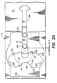
- FIG. 1 is a top plan view of a chamber 11 containing a preferred substrate carriage 13 and temperature adjustment plate 15.
- a central shaft 17 is fixedly coupled to the temperature adjustment plate 15 and extends therefrom through a center region of the substrate carriage 13, Preferably the central shaft 17 is not in contact with the center region of the substrate carriage 13, but rather is coupled to the substrate carriage 13 via a motor (motor 57 in FIGS. 4A and 4B) as described further below with reference to FIGS. 4A and 4B.
- the substrate carriage 13 comprises three equally spaced branches 19a-c which extend radially outward from the center region of the substrate carriage 13. Each branch 19a-c comprises a pair of substrate supports 21a-b which face outwardly (i.e., away from each other) therefrom.
- the branches 19a-c are preferably machined from the same piece of material or may be made of two or more separate parts connected together using bolts, screws or other connectors including welding, such that they rotate and/or elevate together as a unit.
- the branches 19a-c and the substrate supports 21a (e.g., of a first branch 19a) and 21b (e.g., of a second branch 19b) are configured so as to define a plurality of substrate seats 23a-c each of which supports a substrate (not shown) by its edge.
- a passage is maintained for a substrate handler blade 24a of a substrate handler 24 (shown in FIGS. 2A and 2B) to pass therethrough during substrate handoffs between the substrate carriage 13 and the substrate handler blade 24a, as described further below.
- the substrate supports 21a-b are preferably made of a ceramic such as alumina, quartz or any other hard material which is compatible with semiconductor substrates and does not produce particles or scratch a substrate during contact therewith.
- the substrate supports 21a-b are attached to the bottom of the branches 19a-c, such that the substrate carriage 13 may lower the substrate supports 21a-b below the top surface of the temperature adjustment plate 15, and below the substrate handler blade 24a, thus transferring a substrate supported by a substrate seat 23a-c to the temperature adjustment plate 15 and/or to the substrate handler blade 24a, while the remainder of the substrate carriage 13 (i.e., the branches 19a-c) remains above and does not contact either the temperature adjustment plate 15 and/or the substrate handler blade 24a.
- a preferred mechanism for lifting and lowering the substrate supports 21a-b (and the substrate carriage 13) is described below with reference to FIGS. 4A and 4B.
- the temperature adjustment plate 15 is configured to simultaneously support two substrates (not shown), when the substrate carriage 13 lowers the substrate supports 21a-b to an elevation below the top surface of the temperature adjustment plate 15. In order to achieve uniform heating or cooling across the entire substrate surface, the temperature adjustment plate 15 is preferably coextensive with the substrates placed thereon. Thus, in order to allow the substrate supports 21a-b to lower to an elevation below that of the top surface of the temperature adjustment plate 15, the temperature adjustment plate 15 comprises four notches 25a-d placed to receive the substrate supports 21a-b.
- the temperature adjustment plate 15 also comprises a cut out region 26 in which the substrate handler 24 (FIGS. 2A and 2B) may be housed. As best understood with reference to FIGS. 2A and 2B, the cut out region 26 is configured to provide sufficient space for the substrate handler 24 to extend and retract.
- the chamber 11 has two sealable slits 27a-b (e.g., conventional slit valves) positioned on opposite walls of the chamber 11.
- the first slit 27a is disposed to receive substrates from a substrate handler (not shown) which travels among a plurality of transfer chambers (not shown) configured such as transfer chamber 11, and the second slit 27b is coupled to a processing chamber 29, as described in detail in co-pending U.S. Provisional Patent Application Serial No. 60/187,133, filed March 6, 2000 (AMAT No. 4026) , the entire disclosure of which is incorporated herein by this reference.
- the processing chamber 29 is coupled to the slit 27b opposite the substrate handler 24, such that the substrate handler blade 24a travels in a straight line (e.g., along a single axis) to place and extract substrates within and from the processing chamber 29, as further described with reference to FIGS. 2A and 2B.
- FIG. 2A is a top plan view of the chamber 11 of FIG. 1, showing the substrate handler 24 in an extended position
- FIG. 2B is a top plan view of the chamber 11 of FIG. 1 showing the substrate handler 24 in a retracted position
- the exemplary substrate handler 24 of FIGS. 2A-B may be analogized to a human arm having an elbow 24b which extends outwardly when the arm retracts. Such extendable arm type substrate handlers are conventionally employed in semiconductor fabrication and their specific configuration is well known in the art. Accordingly the notch 26 located in the temperature adjustment plate 15 is sized and shaped to accommodate the substrate handler 24's elbow 24b during substrate handler retraction, as shown in FIG. 2B.
- the substrate handler 24 preferably includes a wafer gripping mechanism (not shown) as described in parent application Serial No. 09/332,207 which stabilizes and centers a substrate supported by the blade 24a.
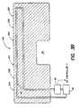
- FIG. 3A is a side elevational view of a temperature adjustment plate 15a configured for heating (i.e., a heat plate 15a) that may be employed as the temperature adjustment plate 15.
- the heating plate 15a has a resistive heating element 31 disposed therein.
- the heating plate 15a may comprise any conventional heated substrate support (e.g., a stainless steel substrate support) having a temperature range sufficient for the heating process to be performed (typically about 150-600°C for most annealing applications).
- a substrate e.g., a semiconductor wafer
- the heating plate 15a of FIG. 3A includes two sets of pins 32a-c for supporting two substrates. Short pin heights facilitate heat transfer from the heating plate 15a to a substrate (not shown) positioned thereon; preferably the pins 32a-c are between .005 - .02 inches in height.
- the heating plate 15a preferably is larger than the diameter of the substrate being heated (e.g., such that the heating plate extends about an inch beyond the diameter of each substrate positioned thereon).
- the heating plate 15a heats a substrate primarily by conduction (e.g., either direct contact conduction if a substrate touches the heating plate 15a or conduction through a dry gas such as nitrogen disposed between the heating plate 15a and a substrate when the substrate rests on the pins 32a-c).
- a convective heating component also may be employed if gas is flowed along the backside of the substrate during heating.
- the heating plate 15a may require an elevated edge (not shown) or an electrostatic chuck (as is known in the art) so as to prevent substrate movement due to such backside gas flow.
- the chamber 11 preferably has a small volume to allow for rapid evacuation of the chamber (described below) and to reduce process gas consumption.
- a gas inlet 33 couples an inert dry gas source 35 (such as a noble gas or nitrogen, preferably 100% N 2 having fewer than a few parts per million of O 2 therein, or 4% or less of H 2 diluted in N 2 and having fewer than a few parts per million of O 2 therein) to the chamber 11.
- the gas emitted from the dry gas source 35 may be further “dried” via a getter or cold trap (not shown) within the gas inlet 33.
- a gas outlet 37 couples the chamber 11 to a vacuum pump 39 which, in operation, pumps gas from the chamber 11.
- the chamber 11 can be periodically or continuously purged with inert gas to remove particles and desorbed gasses from the chamber 11.
- the rate at which the inert gas flows into the chamber 11 is controlled via a needle valve or flow controller 40 (e.g., a mass flow controller) operatively coupled along the gas inlet 33.
- the vacuum pump 39 comprises a rough-pump, such as a dry pump, having a pumping speed of between about 1-50 liters/sec for rapid evacuation of the chamber 11.
- the gas outlet 37 comprises an isolation valve 41, such as a pneumatic roughing port valve, operatively coupled to the vacuum pump 39 so as to control the gas flow rate from the chamber 11 and preferably further comprises a chamber exhaust valve 43 for use during chamber purging.
- a rough pump is capable of evacuating a chamber to a pressure of a few milliTorr or higher
- a rough pump alone may be employed for applications wherein the chamber 11 is not evacuated below a pressure of a few milliTorr (e.g., when the chamber 11 is vented to atmospheric pressure with a non-oxidizing gas such as nitrogen prior to loading a substrate therein or when a substrate is transferred from the chamber 11 to a processing chamber 29 that employs pressures of a few milliTorr or higher).
- a high vacuum pump such as a cryopump also may be employed to allow substrate transfer between a high vacuum processing chamber and the chamber 11 (e.g., in a chamber configured such as that described in parent application Serial No. 09/332,207, which does not employ a temperature adjustment plate 15, or in a chamber wherein the temperature adjustment plate 15 is positioned so as to allow substrate transfer to and from additional processing chambers).
- the chamber 11 may be purged at atmospheric pressure by flowing dry gas from the dry gas source 35 into the chamber 11 with the chamber exhaust valve 43 open, may be single-evacuation purged by evacuating the chamber 11 to a predetermined vacuum level via the pump 39 (by opening the isolation valve 41 coupled therebetween) and then back filling the chamber 11 with dry gas from the dry gas source 35, or may be cycle purged by repeatedly evacuating the chamber 11 to a predetermined vacuum level and then back filling the chamber 11 with dry gas from the dry gas source 35 to further reduce contamination levels beyond those achievable by atmospheric pressure or single evacuation purging.
- a predetermined contamination level e.g., so that less than 10 parts per million of O 2 reside in the chamber 11
- the chamber 11 may be purged at atmospheric pressure by flowing dry gas from the dry gas source 35 into the chamber 11 with the chamber exhaust valve 43 open, may be single-evacuation purged by evacuating the chamber 11 to a predetermined vacuum level via the pump 39 (by opening the isolation valve 41 coupled therebetween) and
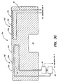
- FIG. 3B is a side elevational view of a temperature adjustment plate 15b configured for substrate cooling (i.e., a cooling plate 15b) that may be employed as the temperature adjustment plate 15 for the chamber 11.
- a cooling plate 15b configured for substrate cooling
- the substrate is placed on the cooling plate 15b via the substrate carriage 13, and water or a refrigerant (e.g., a 50% de-ionized water, 50% glycol solution having a freezing point below that of pure water) is flowed through channels 44 in the cooling plate 15b disposed within the cooling plate 15b.
- a refrigerant e.g., a 50% de-ionized water, 50% glycol solution having a freezing point below that of pure water
- an aluminum cooling plate may be cooled to about 5 to 25°C by a cooling fluid supplied thereto from a cooling fluid source 45 via a pump 47.
- the cooling plate 15b preferably also employs a diffuser design as is known in the art, having up to ten thousand 0.02-0.1 inch diameter holes therein (not shown).
- the holes allow gas to flow through the cooling plate 15b (e.g., from the dry gas source 35) and to be cooled by the cooling plate 15b so as to improve cooling of a substrate positioned thereon (e.g., by cooling a backside of the substrate).
- the cooling plate 15b may require an elevated edge (not shown) or an electrostatic chuck (as is known in the art) so as to prevent substrate movement due to such backside gas flow.
- the walls of the chamber 11 may be the water or refrigerant cooled as well to further enhance substrate cooling.
- FIG. 3C is a top plan view of a temperature adjustment plate 15c configured for both heating and cooling, where a first substrate location (identified by reference numeral 15a') is configured for substrate heating as described with reference to FIG. 3A; and a second substrate location (identified by reference numeral 15b') is configured for substrate cooling as described with reference to FIG. 3B.
- the two substrate locations 15a', 15b' may be part of an integral plate, or may comprise two physically separated plates preferably with a distance of at least one inch therebetween.
- the inventive chamber 11 comprises relatively inexpensive components (e.g., the rotatable substrate carriage 13 and the substrate handler 24 (preferably adapted only for transferring a substrate along a straight line (i.e., a linear substrate handler) such as between the chamber 11 and a processing chamber)). Heating and/or cooling is economically performed with reduced footprint and increased throughput as the need for substrate transfer time to a separate heating and/or cooling module is eliminated.
- a controller C FIG.
- FIGS. 4A and 4B are front cross-sectional views of the preferred substrate carriage 13 in an elevated position and in a lowered position, respectively. As described below, the preferred substrate carriage 13 employs magnetic coupling.
- the central shaft 17 extends upwardly through an aperture 47 in a top surface 11a of the chamber 11.
- a first bellows 49 seals the aperture 47 to an enclosure wall 50, positioned above the chamber 11.
- the enclosure wall 50 encloses an internal magnet support 53 which is fixedly coupled to, or integrally formed with the substrate carriage 13, such that the internal magnet support 53 and the substrate carriage 13 move together as a unit.
- a plurality of internal magnets 51a-n are coupled to the internal magnet support 53 and are spaced from and are magnetically coupled to a plurality of external magnets 55a-n (only external magnets 55a and 55b are shown).
- the internal and external magnets 51a-n, 55a-n preferably are permanent magnets having a number and spacing sufficient to allow the internal magnets 51a-n (and the substrate carriage 13 coupled thereto) to rotate when the external magnets 55a-n are rotated, and to elevate (i.e., lift or lower) when the external magnets 55a-n are elevated.
- the internal magnets 51a-n and four external magnets 55a-n are equally spaced, although other numbers of magnets and other magnet spacings may be employed depending on such factors as magnet strength, the material that separates the internal and external magnets (e.g., the material used for the enclosure wall 50), the torque exerted on the external magnets during rotation, etc.
- a motor 57 is coupled to the external magnets 55a-n, to the central shaft 17 via a slideable connection 59 (e.g., a guide rail connection) so as to slide vertically along the central shaft 17, and to the internal magnet support 53 via a plurality of bearings 61a-n.
- the motor 57 preferably comprises both a rotational motor portion 57a for providing rotational motion to the external magnets 55a-n (and thus to the internal magnets 51a-n and to the substrate carriage 13) and a linear motor portion 57b for translating the external magnets 55a-n (and thus the internal magnets 51a-n and the substrate carriage 13) relative to the central shaft 17 (as described below).
- Both the motor 57 and the central shaft 17 are coupled to a supporting structure 63 (e.g. an equipment chassis, or any other support structure).
- a second bellows 65 seals the chamber 11 from particles/contaminants generated by the slideable connection 59 which exists between the motor 57 and the central shaft 17.
- the rotational motor portion 57a of the motor 57 is energized (e.g., by applying AC or DC power thereto as is known in the art) so as to exert rotational force on the external magnets 55a-n (e.g., via a rotor 64 of the rotational motor portion 57a). Due to magnetic coupling between the internal and external magnets 51a-n, 55a-n, as the external magnets 55a-n rotate under the applied rotational force, the internal magnets 51a-n and the substrate carriage 13 coupled thereto also rotate.
- the bearings 61a-n allow the internal magnet support 53 to rotate freely relative to the stationary portions of the motor 57.
- the substrate carriage 13 (which is fixedly coupled to the internal magnet support 53) thereby is rotated, and may be rotated 360° if the rotational motor portion 57a is energized for a sufficient time period.
- the linear motor portion 57b of the motor 57 is employed to translate the substrate carriage 13 relative to the central shaft 17.
- the linear motor portion 57b of the motor 57 is energized so that a translating portion 67 (e.g., a motor shaft) of the linear motor portion 57b is extended.
- a translating portion 67 e.g., a motor shaft
- the remainder of the motor 57 is pushed away from the stationary structure 63 while the central shaft 17 remains stationary.
- the motor 57 (with the exception of the translating portion 67) slides along the slideable connection 59 toward the temperature adjustment plate 15, translating the external magnets 55a-n, the internal magnets 51a-n and the substrate carriage 13 (each of which are coupled either directly or via bearings to the motor 57) toward the temperature adjustment plate 15.
- the substrate carriage 13 thereby is lowered.
- a controller 69 (or the controller C of FIG. 1) is coupled to the motor 57 and is programmed to control the operation/timing of the raising, lowering and rotating functions of the substrate carriage 13 described above.
- FIGS. 5A and 5B are a front elevational view and a side elevational view, respectively, of the chamber 11, employing a preferred magnetically levitated and magnetically coupled substrate handler 71, rather than the substrate handler 24 of FIGS. 2A and 2B.
- the substrate handler 71 comprises a blade 73 mounted on a first end of a shaft 75, and a disk 77 mounted on a second end of the shaft 75.
- the disk 77 is configured to support four vertically arranged and radially disposed magnets 79a-d (e.g., four magnets approximately equally spaced about the disk 77 as shown).
- the magnets 79a-d preferably comprise electromagnets. As shown in FIGS.
- the shaft 75 extends through an elongated opening 81 located in the bottom wall of the transfer chamber 11.
- the opening 81 extends from the temperature adjustment plate 15 toward the processing chamber 29 a distance sufficient to place the substrate handler 71 beneath one of the substrate seats 23a-c of the substrate carriage 13 when the substrate handler 71 is in a retracted position, and sufficient to place the blade 73 of the substrate handler 71 above a substrate support (not shown) located within the processing chamber 29.
- the substrate handler 21 may transport a substrate between the substrate carriage 13 and a processing chamber 29.
- An external channel wall 83 is sealed to (or may be integrally formed with) the chamber 11 and is coextensive with the opening B1.
- the external channel wall B3 is preferably configured to allow magnetic coupling therethrough.
- the substrate handler 71 is disposed such that the disk 77 is contained within the external channel wall 83, and such that the shaft 75 extends through the elongated opening 81 into the chamber 11 a distance sufficient to place the blade 73 at the same elevation as a top surface 82 of the temperature adjustment plate 15.
- a rail 85 extends along the length of the external chamber wall 83.
- a bracket 87 having four external magnets 89a-d (e.g., magnets) is mounted to the rail 85 and is coupled to a motor 91 such that the motor 91 drives the bracket 87 forward and backward along the rail 85.
- the external magnets 89a-d are vertically arranged and are radially disposed along the inner surface of the bracket 87 so as to be adjacent the outer surface of the external channel wall 83 and so as to magnetically couple to the internal magnets 79a-d.
- a distance sensor 93a-d is positioned adjacent each internal/external magnet pair so as to sense the distance therebetween.
- the sensors 93a-d, the external magnets 89a-d and the motor 91 are each coupled to a controller 94 (or to the controller C of FIG, 1), and the controller is adapted to independently adjust the magnetization level of the external magnets 89a-d (e.g., by adjusting the current supplied to each magnet 89a-d) so as to maintain equal spacing between the magnet pairs, and thus to maintain the robot blade 73 in a level position.
- the substrate carriage 13 positions a substrate (not shown) above the blade 73 of the substrate handler 71.
- the substrate carriage 13 then lowers such that the blade 73 passes through the substrate seat 23 lifting the substrate therefrom.
- the slit 27b that separates the chamber 11 and the processing chamber 29 also is opened.
- the motor 91 is energized so as to move the bracket 87 along the rail 85 toward the processing chamber 29 at a speed which will maintain magnetic coupling between the internal magnets 79a-d and the external magnets 89a-d.
- the distance sensors 93a-d measure the distance between the internal magnets 79a-d and the external magnets B9a-d.
- the controller 94 also adjusts the speed at which the motor 91 moves the bracket 87 along the rail 85, reducing the speed if the distance sensors 93a-d detect the bracket B7 is moving too quickly to maintain sufficient magnetic coupling between the internal and external magnet pairs.
- the substrate handler 71 travels forward in the manner described above to extract the substrate from the processing chamber 29. While the substrate handler 71 is within the processing chamber 29, the substrate carriage 13 lowers to a position below the elevation of the substrate handler's blade 73. The substrate handler 71 then retracts carrying the substrate into position above the substrate carriage 13. The substrate carriage 13 elevates lifting the substrate from the substrate handler's blade 73, and simultaneously lifting any substrates positioned on the temperature adjustment plate 15 therefrom. The substrate carriage 13 rotates carrying the substrate retrieved from the processing chamber 29 (the "first" processed substrate) to a position above the temperature adjustment plate 15 and carrying one of the substrates lifted from the temperature adjustment plate 15 into position above the substrate handler 71. The substrate carriage 13 then lowers transferring the substrates from the substrate carriage 13 to the temperature adjustment plate 15 and to the substrate handler 71.
- a second substrate is then loaded into the processing chamber 29 as described above and, depending on the configuration of the temperature adjustment plate 15, the first processed substrate is either cooled on the temperature adjustment plate 15, heated by the temperature adjustment plate 15 (e.g., as an annealing step) or immediately extracted therefrom by a front-end loader robot (not shown).
- the front-end loader robot places a new "third" substrate on a first side of the temperature adjustment plate 15 and extracts the first processed substrate from the second side of the temperature adjustment plate 15.
- the sequence of substrate heating, cooling and processing may vary according to the requirements of the fabrication process being performed.
- a substrate may be degassed via the temperature adjustment plate 15 prior to entry into the processing chamber 29, and/or cooled, annealed or annealed and cooled by the temperature adjustment plate 15 after processing within the processing chamber 29.
- an additional advantage of the inventive substrate handling apparatus described herein is that various components (e. g., the temperature adjustment plate 15, the substrate carriage 13, the substrate handler 24, the magnetically levitated and magnetically coupled substrate handler 71, etc.) are each coupled either directly or indirectly to only one surface of the chamber 11 (e.g., a bottom surface 11b as shown in FIGS. 4A and 4B). Accordingly, as the walls of the chamber 11 deflect during evacuation or venting of the chamber 11 (e.g., due to the generation or elimination of a large pressure differential between the interior and exterior environments of the chamber 11) substrate transfer is unaffected as all substrate handling and/or supporting components are identically affected by such deflections.
- various components e. g., the temperature adjustment plate 15, the substrate carriage 13, the substrate handler 24, the magnetically levitated and magnetically coupled substrate handler 71, etc.
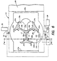
- FIG. 6 is a top plan view of a chamber 111 containing a substrate carriage 13 and a temperature adjustment plate 115 coupled to a plurality of processing chambers 29a-c; and FIG. 7 is a side cross-sectional view of the chamber of FIG. 6 taken along line 7-7 of FIG. 6.
- the components of the chamber 111 are substantially the same as those shown and described with reference to FIG. 1-5A. Accordingly, only the aspects which differ from FIGS. 1-5A will be described with reference to FIGS. 6 and 7.
- the temperature adjustment plate 115 is located above the substrate carriage 13, but is supported by a lower chamber wall 11b as shown in FIG. 7, In this embodiment no temperature adjustment plate 15 is present below the substrate carriage 13.
- the substrate handler 24 may rotate freely, unlike the configuration of FIGS 1-5A in which the temperature adjustment plate 15 is positioned below the substrate carriage 13.
- a plurality of chambers e.g., loadlock L, processing chambers 29a-c
- substrates may be transferred between the chambers via the substrate handler 24, in contrast to the embodiment of FIG. 1 where the substrate handler 24 can serve only one chamber because the temperature adjustment plate 15 blocks access elsewhere.
- the temperature adjustment plate 115 is supported by the bottom surface 11b of the chamber on a support 201, and extends from the support 201 to a position overlying the positions of wafers supported on the substrate carriage 13, and is sized so as to be smaller (e.g., has a smaller diameter) than the passage P between the opposing pairs of branches 19a-c and substrate supports 21a-b which form the substrate seats 23a-c.
- Notches 125a-b may be formed in the temperature adjustment plate so that a portion of the substrate supports 21a-b may pass therethrough (e.g., the notches 125a-b may mirror the shape of the inwardly extending portions of the substrate support, as shown in FIG. 6).
- the substrates In operation, the substrates must be moved to be positioned on the top surface of the temperature adjustment plate 115. To do so, the substrate carriage 13 first rotates until an empty substrate seat 23a-c is positioned below the temperature adjustment plate 115. The substrate carriage 13 then elevates to an elevation above that of the temperature adjustment plate 115, the temperature adjustment plate 115 passes through an empty slot of the substrate carriage 13.
- the substrate carriage 13 rotates to position a substrate above the temperature adjustment plate 115 and then lowers to an elevation below the temperature adjustment plate 115.
- the substrate carriage 13 lowers the opposing branches 19a-c and the substrate supports coupled thereto, lower along either side of the temperature adjustment plate 115, such that the substrate seated on the opposing substrate supports is transferred to the temperature adjustment plate 115 and the substrate carriage 13 is again below the temperature adjustment plate 115.
- the substrate carriage 13 and the substrate handler 23 are then able to transfer other substrates around the chamber 111 and/or among the processing chambers 29a-c and loadlock L.
- the substrate carriage 13 elevates such that an empty substrate seat lifts the substrate from the temperature adjustment plate 115.
- the substrate carriage 13 rotates to position an empty substrate seat 23a-c above the temperature adjustment plate 115 and then lowers therepast.
- the temperature adjustment plate 115 may be configured with heating or cooling components such as those described with reference to FIGS. 3A-C.
- the temperature adjustment plate 115 may be coupled to any of the chamber 111's sidewalls, or may be coupled via a support 201 that may extend downward from the upper surface 11a of the chamber 11, or that may extend upwardly from the bottom surface 11b of the chamber 111, as shown in FIG. 6.
- the substrate carriage 13 and the substrate handler 24, 71 are each coupled either directly or indirectly to only one surface of the chamber 11 (e.g., the bottom surface 11b as ahown in FIG.
- substrate carriages and substrate handlers which are both magnetically coupled and magnetically levitated are preferred, substrate carriages and substrate handlers which are not magnetically coupled or magnetically levitated may be employed.
- the invention may be advantageously employed with a substrate handler preferably adapted only for transferring a substrate along a straight line (a linear substrate handler), other types of substrate handlers may be employed.
- the inventive magnetically coupled and magnetically levitated substrate handler may be employed within a transfer chamber such as that described in parent application Serial No. 09/332,207 which requires the substrate handler to transport substrates between the substrate carriage and various processing or load lock chambers.
- the inventive magnetically coupled substrate carriage may be employed in other transfer chamber's such as those described in parent application Serial No. 09/332,207, as may the temperature adjustment plate.
- the concept of heating or cooling a substrate via a heating and/or cooling mechanism contained within a transfer chamber may be employed within other chambers, and is not to be limited to the specific chambers described herein.
- An inventive indexing pod door opener may eliminate the need for a separate front end robot.
- the pod door opener is provided with vacuum pump/vent capability so that the pod door may operate as a load lock.
- the substrate carriage chamber's robot may directly extract wafers from the pod door opener.
- the substrate carriage chamber's robot stroke need not be lengthened because the chamber is designed such that the robot can load/unload wafers from processing chambers, and loading/unloading from one or more processing chambers requires the same stroke as does loading and unloading wafers from the pod door opener.
- the pod door opener may index vertically to eliminate the need for the pod door receiver to move the pod door vertically to allow access to wafers contained within the pod, and to eliminate the need for the loading/unloading robot to index vertically.
- numerous chambers configured in accordance with the invention may be coupled via pass-through tunnels and may allow creation of a staged vacuum system and/or a transfer chamber than is not exposed to atmosphere.
Landscapes
- Container, Conveyance, Adherence, Positioning, Of Wafer (AREA)
Abstract
A method and apparatus (11) are provided for
substrate handling. In a first aspect, a temperature
adjustment plate (15) is located below a substrate
carriage (13) and is configured such that a substrate
may be transferred between the temperature adjustment
plate and the substrate carriage by lifting and
lowering the substrate carriage above and below the
top surface of the temperature adjustment plate. The
temperature adjustment plate may be configured to heat
and/or cool a substrate positioned thereon. In a
second aspect, the substrate carriage (13) is
magnetically coupled so as to rotate and/or lift and
lower magnetically, thereby reducing particle
generation via contact between moving parts (and
potential chamber contamination therefrom). In a
third aspect, a substrate handler (24) positioned
below the substrate carriage is magnetically coupled
and/or magnetically levitated, providing further
particle reduction. In a fourth aspect, the transfer
chamber (11) has a temperature adjustment plate (15b)
located in an upper portion of the chamber, above the
substrate carriage and the substrate handler.
Description
- The present invention relates to substrate processing, and more particularly to a method and apparatus for improved substrate handling.
- Cluster tools are commonly used in the fabrication of integrated circuits. A cluster tool typically includes a load lock chamber for introducing substrates (e.g., semiconductor wafers) into the tool and a central transfer chamber for moving substrates between the load lock chamber and a plurality of processing chambers and one or more cool down chambers mounted on the transfer chamber. Typically, either a single blade or a double blade robot is located within the transfer chamber to move substrates between the load lock chamber, the processing chambers, the cool down chamber(s) and then back to the load lock chamber. Exemplary cluster tools, robots and substrate handling methods are described in U.S. Patent Nos. 4,951,601 and 5,292,393, both of which are incorporated herein by reference in their entirety.
- Within a cluster tool a typical substrate handler arm capable of 360° rotation and extension is positioned inside the central transfer chamber. In operation the substrate handler rotates to align its blade with a sealable slit (e.g., a slit valve) which connects the central transfer chamber to a load lock chamber (i.e., a load lock slit). The substrate handler extends through the load lock slit, picks up a substrate, retracts, rotates to position the substrate in front of a processing chamber slit (which connects the central transfer chamber with the processing chamber) and extends through the slit to place the substrate in the processing chamber. After the processing chamber finishes processing the substrate, the wafer handler extends through the processing chamber slit, picks of the substrate, retracts and rotates to position the substrate in front of a cool down chamber slit. The substrate handler again extends placing the substrate in the cool down chamber and then retracts therefrom. After substrate cooling is complete, the substrate handler extends through the cool down chamber slit, picks up the substrate and retracts through the cool down chamber slit in order to extract the substrate and carry the substrate to another processing chamber or return the substrate to the load lock chamber. While the substrate is processing or cooling, the substrate handler places and extracts other substrates from the remaining chambers (e.g., load lock, processing or cool down chambers) in the same manner. Thus, the substrate handler undergoes a complex pattern of rotations and extensions, requiring a mechanically complex and expensive substrate handler. Further, each substrate handler extension and rotation requires considerable operating space and may introduce reliability problems.
- One way to improve system efficiency is to provide a robot arm having the ability to handle two substrates at the same time. Thus, some equipment manufacturers have provided a robot arm in which two carrier blades are rotated about a pivot point at the robot wrist (e.g., via a motor and belt drive positioned at the substrate handler's wrist). Thus, a first substrate (e.g., to be processed) may be stored on one blade while the other blade picks up a second substrate (e.g., previously processed). The carrier blades are then rotated and the first stored substrate is placed as desired. Such a mechanism is rather complex and requires a massive arm assembly to support the weight of a carrier blade drive located at the end of an extendible robot arm. For example, three drives are usually required for a system incorporating such a robot arm: one drive to rotate the arm, one drive to extend the arm, and one drive to rotate the carrier blades. Any improvement in throughput provided by such a multiple carrier robot comes at a price of increased equipment/manufacturing cost, increased weight and power consumption, and increased complexity and, thus, reduced reliability and serviceability.
- Another approach places two robot arms coaxially about a common pivot point. Each such robot arm operates independently of the other and improved throughput can be obtained through the increased handling capacity of the system. However, it is not simple to provide two robot arms for independent operation about a common axis. Thus, multiple drives must be provided, again increasing manufacture/equipment costs and complexity while reducing reliability.
- The various processes which are performed on the various substrates, may require different processing times. Therefore, some substrates may remain in a chamber for a short period of time after processing is completed before they are moved into a subsequent processing chamber because the subsequent processing chamber is still processing another substrate. This causes a substrate back log and decreases system throughput.
- In addition to varying processing times, another factor which affects throughput is the need to cool individual substrates following processing. Specifically, the number of movements a substrate handler must make in order to process numerous substrates increases significantly when the substrates must be transferred to one or more cool down chambers following each processing step. Additionally, incorporation of one or more cool down chambers reduces the number of positions on the transfer chamber where a processing chamber may be positioned. Fewer processing chambers can result in lower system throughput and can increase the coat of each wafer processed.
- Therefore, there remains a need for a method and apparatus for improved substrate handling module which can increase substrate throughput while preferably providing substrate cooling.
- Embodiments of the present invention improve upon the "Carousel Wafer Transfer System" described in U.S. Patent Application Serial No. 09/332,207 from which this application is a continuation-in-part. Various embodiments of the invention provide aspects which enhance substrate heating and cooling efficiency, reduce substrate handler complexity, reduce contact between moving parts during substrate transfer operation (e.g., reducing particle generation associated therewith), improve substrate handling equipment reliability, and/or increase substrate throughput.
- In a first aspect, the invention comprises a temperature adjustment plate located below a substrate carriage (such as the rotatable carousel described in the parent application Serial No. 09/332,207) and configured such that a substrate may be transferred between the temperature adjustment plate and the substrate carriage, by lifting and lowering the substrate carriage above and below the top surface of the temperature adjustment plate. The temperature adjustment plate may be configured to heat and/or cool a substrate positioned thereon,
- In a second aspect, the substrate carriage is magnetically coupled so as to rotate and/or lift and lower magnetically, thereby reducing particle generation via contact between moving parts (and potential chamber contamination therefrom).
- In a third aspect, a substrate handler positioned below the substrate carriage is both magnetically coupled and magnetically levitated, providing further particle reduction. The magnetic levitation is preferably achieved via four radially disposed and vertically arranged magnet pairs having distance sensors for maintaining desired spacing therebetween.
- In a fourth aspect, the transfer chamber contains a rotatable substrate carriage, and a temperature adjustment plate located in an upper portion of the chamber and a substrate handler located in a lower portion of the chamber. The substrate carriage is adapted so as to raise and lower between an elevation below an elevation of the substrate handler's blade, and an elevation above the elevation of the substrate supporting surface of the temperature adjustment. plate so as to place and extract substrates to and from the substrate handler's blade and the temperature adjustment plate.
- In a preferred embodiment, one substrate is heated/degassed via a temperature adjustment plate in preparation for processing while a second substrate is processed, and a third processed substrate is cocled via a temperature adjustment plate. Two separate temperature adjustment plates or differing portions of a single plate may be employed. An advantage of this arrangement is that the chamber containing the substrate carriage requires only a small volume of operating space, and may be quickly pumped to vacuum pressure. Thus, certain embodiments need not employ a separate load lock chamber.
- Other features and advantages of the present invention will become more fully apparent from the following detailed description of the preferred embodiments, the appended claims and the accompanying drawings in which:
- FIG. 1 is a top plan view of a chamber containing a preferred substrate carriage and temperature adjustment plate;
- FIG. 2A is a top plan view of the chamber of FIG. 1 showing a substrate handler in an extended position;
- FIG. 2B is a top plan view of the chamber of FIG. 1 showing a substrate handler in a retracted position;
- FIG. 3A is a side elevational view of a temperature adjustment plate configured for heating;
- FIG. 3B is a side elevational view of a temperature adjustment plate configured for cooling;
- FIG. 3C is a side elevational view of a temperature adjustment plate configured for both heating and cooling;
- FIG. 4A is a front elevational view showing a magnetically coupled substrate carrier in an elevated position;
- FIG. 4B is a front elevational view showing a magnetically coupled substrate carrier in a lowered position;
- FIG. 5A is a front elevational view of the chamber of FIG. 1, containing a preferred magnetically levitated and magnetically coupled substrate handler;
- FIG. 5B is a side elevational view of the chamber of FIG. 1, containing the preferred magnetically levitated and magnetically coupled substrate handler of FIG. 5A;
- FIG. 6 is a top plan view of a chamber similar to that of FIG. 1, containing a substrate carriage and an elevated temperature adjustment plate on which a substrate may be placed; and
- FIG. 7 is a side cross-sectional view of the chamber of FIG. 6, taken along line 7-7 of FIG. 6.
-
- FIG. 1 is a top plan view of a
chamber 11 containing apreferred substrate carriage 13 andtemperature adjustment plate 15. Acentral shaft 17 is fixedly coupled to thetemperature adjustment plate 15 and extends therefrom through a center region of thesubstrate carriage 13, Preferably thecentral shaft 17 is not in contact with the center region of thesubstrate carriage 13, but rather is coupled to thesubstrate carriage 13 via a motor (motor 57 in FIGS. 4A and 4B) as described further below with reference to FIGS. 4A and 4B. Thesubstrate carriage 13 comprises three equally spacedbranches 19a-c which extend radially outward from the center region of thesubstrate carriage 13. Eachbranch 19a-c comprises a pair of substrate supports 21a-b which face outwardly (i.e., away from each other) therefrom. Thebranches 19a-c are preferably machined from the same piece of material or may be made of two or more separate parts connected together using bolts, screws or other connectors including welding, such that they rotate and/or elevate together as a unit. Thebranches 19a-c and the substrate supports 21a (e.g., of afirst branch 19a) and 21b (e.g., of asecond branch 19b) are configured so as to define a plurality ofsubstrate seats 23a-c each of which supports a substrate (not shown) by its edge. By placing a substrate (not shown) on a pair of substrate supports 21a-b secured to adjacent branches (e.g.,branches branches branches substrate handler blade 24a of a substrate handler 24 (shown in FIGS. 2A and 2B) to pass therethrough during substrate handoffs between thesubstrate carriage 13 and thesubstrate handler blade 24a, as described further below. - The substrate supports 21a-b are preferably made of a ceramic such as alumina, quartz or any other hard material which is compatible with semiconductor substrates and does not produce particles or scratch a substrate during contact therewith. The substrate supports 21a-b are attached to the bottom of the
branches 19a-c, such that thesubstrate carriage 13 may lower the substrate supports 21a-b below the top surface of thetemperature adjustment plate 15, and below thesubstrate handler blade 24a, thus transferring a substrate supported by asubstrate seat 23a-c to thetemperature adjustment plate 15 and/or to thesubstrate handler blade 24a, while the remainder of the substrate carriage 13 (i.e., thebranches 19a-c) remains above and does not contact either thetemperature adjustment plate 15 and/or thesubstrate handler blade 24a. A preferred mechanism for lifting and lowering the substrate supports 21a-b (and the substrate carriage 13) is described below with reference to FIGS. 4A and 4B. - The
temperature adjustment plate 15 is configured to simultaneously support two substrates (not shown), when thesubstrate carriage 13 lowers the substrate supports 21a-b to an elevation below the top surface of thetemperature adjustment plate 15. In order to achieve uniform heating or cooling across the entire substrate surface, thetemperature adjustment plate 15 is preferably coextensive with the substrates placed thereon. Thus, in order to allow the substrate supports 21a-b to lower to an elevation below that of the top surface of thetemperature adjustment plate 15, thetemperature adjustment plate 15 comprises fournotches 25a-d placed to receive the substrate supports 21a-b. Preferably thetemperature adjustment plate 15 also comprises a cut outregion 26 in which the substrate handler 24 (FIGS. 2A and 2B) may be housed. As best understood with reference to FIGS. 2A and 2B, the cut outregion 26 is configured to provide sufficient space for thesubstrate handler 24 to extend and retract. - Preferably the
chamber 11 has twosealable slits 27a-b (e.g., conventional slit valves) positioned on opposite walls of thechamber 11. Preferably thefirst slit 27a is disposed to receive substrates from a substrate handler (not shown) which travels among a plurality of transfer chambers (not shown) configured such astransfer chamber 11, and thesecond slit 27b is coupled to aprocessing chamber 29, as described in detail in co-pending U.S. Provisional Patent Application Serial No. 60/187,133, filed March 6, 2000 (AMAT No. 4026) , the entire disclosure of which is incorporated herein by this reference. Theprocessing chamber 29 is coupled to theslit 27b opposite thesubstrate handler 24, such that thesubstrate handler blade 24a travels in a straight line (e.g., along a single axis) to place and extract substrates within and from theprocessing chamber 29, as further described with reference to FIGS. 2A and 2B. - FIG. 2A is a top plan view of the
chamber 11 of FIG. 1, showing thesubstrate handler 24 in an extended position, and FIG. 2B is a top plan view of thechamber 11 of FIG. 1 showing thesubstrate handler 24 in a retracted position. Theexemplary substrate handler 24 of FIGS. 2A-B may be analogized to a human arm having anelbow 24b which extends outwardly when the arm retracts. Such extendable arm type substrate handlers are conventionally employed in semiconductor fabrication and their specific configuration is well known in the art. Accordingly thenotch 26 located in thetemperature adjustment plate 15 is sized and shaped to accommodate thesubstrate handler 24'selbow 24b during substrate handler retraction, as shown in FIG. 2B. Thesubstrate handler 24 preferably includes a wafer gripping mechanism (not shown) as described in parent application Serial No. 09/332,207 which stabilizes and centers a substrate supported by theblade 24a. - FIG. 3A is a side elevational view of a
temperature adjustment plate 15a configured for heating (i.e., aheat plate 15a) that may be employed as thetemperature adjustment plate 15. Theheating plate 15a has aresistive heating element 31 disposed therein. Theheating plate 15a may comprise any conventional heated substrate support (e.g., a stainless steel substrate support) having a temperature range sufficient for the heating process to be performed (typically about 150-600°C for most annealing applications). A substrate (e.g., a semiconductor wafer) may be placed directly on theheating plate 15a (e.g., via the substrate carriage 13); or optionally, on a plurality of pins 32 (preferably 3-6 pins, most preferably threepins 32a-c per substrate as shown in FIGS. 2A and 2B) which extend from theheating plate 15a, so as to facilitate gas flow along the backside of the substrate and so as to reduce contact between the substrate and theheating plate 15a (thereby reducing particle generation by such contact). Theheating plate 15a of FIG. 3A includes two sets ofpins 32a-c for supporting two substrates. Short pin heights facilitate heat transfer from theheating plate 15a to a substrate (not shown) positioned thereon; preferably thepins 32a-c are between .005 - .02 inches in height. - To improve substrate temperature uniformity during heating, the
heating plate 15a preferably is larger than the diameter of the substrate being heated (e.g., such that the heating plate extends about an inch beyond the diameter of each substrate positioned thereon). Theheating plate 15a heats a substrate primarily by conduction (e.g., either direct contact conduction if a substrate touches theheating plate 15a or conduction through a dry gas such as nitrogen disposed between theheating plate 15a and a substrate when the substrate rests on thepins 32a-c). A convective heating component also may be employed if gas is flowed along the backside of the substrate during heating. However, theheating plate 15a may require an elevated edge (not shown) or an electrostatic chuck (as is known in the art) so as to prevent substrate movement due to such backside gas flow. - The
chamber 11 preferably has a small volume to allow for rapid evacuation of the chamber (described below) and to reduce process gas consumption. As shown in FIG. 1, agas inlet 33 couples an inert dry gas source 35 (such as a noble gas or nitrogen, preferably 100% N2 having fewer than a few parts per million of O2 therein, or 4% or less of H2 diluted in N2 and having fewer than a few parts per million of O2 therein) to thechamber 11. The gas emitted from thedry gas source 35 may be further "dried" via a getter or cold trap (not shown) within thegas inlet 33. Agas outlet 37 couples thechamber 11 to avacuum pump 39 which, in operation, pumps gas from thechamber 11. Thus thechamber 11 can be periodically or continuously purged with inert gas to remove particles and desorbed gasses from thechamber 11. - The rate at which the inert gas flows into the
chamber 11 is controlled via a needle valve or flow controller 40 (e.g., a mass flow controller) operatively coupled along thegas inlet 33. Preferably, thevacuum pump 39 comprises a rough-pump, such as a dry pump, having a pumping speed of between about 1-50 liters/sec for rapid evacuation of thechamber 11. Thegas outlet 37 comprises anisolation valve 41, such as a pneumatic roughing port valve, operatively coupled to thevacuum pump 39 so as to control the gas flow rate from thechamber 11 and preferably further comprises achamber exhaust valve 43 for use during chamber purging. Because a rough pump is capable of evacuating a chamber to a pressure of a few milliTorr or higher, a rough pump alone may be employed for applications wherein thechamber 11 is not evacuated below a pressure of a few milliTorr (e.g., when thechamber 11 is vented to atmospheric pressure with a non-oxidizing gas such as nitrogen prior to loading a substrate therein or when a substrate is transferred from thechamber 11 to aprocessing chamber 29 that employs pressures of a few milliTorr or higher). However, for applications that require pressures below a few milliTorr (e.g., pressures which cannot be obtained with a rough pump alone), a high vacuum pump (not shown) such as a cryopump also may be employed to allow substrate transfer between a high vacuum processing chamber and the chamber 11 (e.g., in a chamber configured such as that described in parent application Serial No. 09/332,207, which does not employ atemperature adjustment plate 15, or in a chamber wherein thetemperature adjustment plate 15 is positioned so as to allow substrate transfer to and from additional processing chambers). - To pre-condition the
chamber 11 to a predetermined contamination level (e.g., so that less than 10 parts per million of O2 reside in the chamber 11) thechamber 11 may be purged at atmospheric pressure by flowing dry gas from thedry gas source 35 into thechamber 11 with thechamber exhaust valve 43 open, may be single-evacuation purged by evacuating thechamber 11 to a predetermined vacuum level via the pump 39 (by opening theisolation valve 41 coupled therebetween) and then back filling thechamber 11 with dry gas from thedry gas source 35, or may be cycle purged by repeatedly evacuating thechamber 11 to a predetermined vacuum level and then back filling thechamber 11 with dry gas from thedry gas source 35 to further reduce contamination levels beyond those achievable by atmospheric pressure or single evacuation purging. - FIG. 3B is a side elevational view of a
temperature adjustment plate 15b configured for substrate cooling (i.e., acooling plate 15b) that may be employed as thetemperature adjustment plate 15 for thechamber 11. Specifically, to affect rapid cooling of a substrate following substrate heating within theprocessing chamber 29 the substrate is placed on thecooling plate 15b via thesubstrate carriage 13, and water or a refrigerant (e.g., a 50% de-ionized water, 50% glycol solution having a freezing point below that of pure water) is flowed through channels 44 in thecooling plate 15b disposed within thecooling plate 15b. For example, an aluminum cooling plate may be cooled to about 5 to 25°C by a cooling fluid supplied thereto from a coolingfluid source 45 via apump 47. - The
cooling plate 15b preferably also employs a diffuser design as is known in the art, having up to ten thousand 0.02-0.1 inch diameter holes therein (not shown). The holes allow gas to flow through thecooling plate 15b (e.g., from the dry gas source 35) and to be cooled by thecooling plate 15b so as to improve cooling of a substrate positioned thereon (e.g., by cooling a backside of the substrate). Like theheating plate 15a thecooling plate 15b may require an elevated edge (not shown) or an electrostatic chuck (as is known in the art) so as to prevent substrate movement due to such backside gas flow. The walls of thechamber 11 may be the water or refrigerant cooled as well to further enhance substrate cooling. - FIG. 3C is a top plan view of a
temperature adjustment plate 15c configured for both heating and cooling, where a first substrate location (identified byreference numeral 15a') is configured for substrate heating as described with reference to FIG. 3A; and a second substrate location (identified by reference numeral 15b') is configured for substrate cooling as described with reference to FIG. 3B. The twosubstrate locations 15a', 15b' may be part of an integral plate, or may comprise two physically separated plates preferably with a distance of at least one inch therebetween. - Regardless of the specific
temperature adjustment plate 15a-c which theinventive chamber 11 employs, theinventive chamber 11 comprises relatively inexpensive components (e.g., therotatable substrate carriage 13 and the substrate handler 24 (preferably adapted only for transferring a substrate along a straight line (i.e., a linear substrate handler) such as between thechamber 11 and a processing chamber)). Heating and/or cooling is economically performed with reduced footprint and increased throughput as the need for substrate transfer time to a separate heating and/or cooling module is eliminated. A controller C (FIG. 1) is coupled to the various chamber components (e.g., to thetemperature adjustment plate 15, to theflow controller 40, to theisolation valve 41, to thechamber exhaust valve 43, to the coolingfluid source 45, to theheating element 31, to thesubstrate handler 24, to themotor 57, etc.) and is programmed so as to cause theinventive chamber 11 to perform the inventive method described below. - FIGS. 4A and 4B are front cross-sectional views of the
preferred substrate carriage 13 in an elevated position and in a lowered position, respectively. As described below, thepreferred substrate carriage 13 employs magnetic coupling. - With reference to FIGS. 4A and 4B, the
central shaft 17 extends upwardly through anaperture 47 in a top surface 11a of thechamber 11. A first bellows 49 seals theaperture 47 to anenclosure wall 50, positioned above thechamber 11. Theenclosure wall 50 encloses aninternal magnet support 53 which is fixedly coupled to, or integrally formed with thesubstrate carriage 13, such that theinternal magnet support 53 and thesubstrate carriage 13 move together as a unit. - As shown in FIGS. 4A and 4B, a plurality of
internal magnets 51a-n (onlyinternal magnets internal magnet support 53 and are spaced from and are magnetically coupled to a plurality ofexternal magnets 55a-n (onlyexternal magnets external magnets 51a-n, 55a-n preferably are permanent magnets having a number and spacing sufficient to allow theinternal magnets 51a-n (and thesubstrate carriage 13 coupled thereto) to rotate when theexternal magnets 55a-n are rotated, and to elevate (i.e., lift or lower) when theexternal magnets 55a-n are elevated. Preferably there are fourinternal magnets 51a-n and fourexternal magnets 55a-n, each equally spaced, although other numbers of magnets and other magnet spacings may be employed depending on such factors as magnet strength, the material that separates the internal and external magnets (e.g., the material used for the enclosure wall 50), the torque exerted on the external magnets during rotation, etc. - A
motor 57 is coupled to theexternal magnets 55a-n, to thecentral shaft 17 via a slideable connection 59 (e.g., a guide rail connection) so as to slide vertically along thecentral shaft 17, and to theinternal magnet support 53 via a plurality of bearings 61a-n. Themotor 57 preferably comprises both arotational motor portion 57a for providing rotational motion to theexternal magnets 55a-n (and thus to theinternal magnets 51a-n and to the substrate carriage 13) and alinear motor portion 57b for translating theexternal magnets 55a-n (and thus theinternal magnets 51a-n and the substrate carriage 13) relative to the central shaft 17 (as described below). Both themotor 57 and thecentral shaft 17 are coupled to a supporting structure 63 (e.g. an equipment chassis, or any other support structure). A second bellows 65 seals thechamber 11 from particles/contaminants generated by theslideable connection 59 which exists between themotor 57 and thecentral shaft 17. - In operation, to rotate the
substrate carriage 13, therotational motor portion 57a of themotor 57 is energized (e.g., by applying AC or DC power thereto as is known in the art) so as to exert rotational force on theexternal magnets 55a-n (e.g., via arotor 64 of therotational motor portion 57a). Due to magnetic coupling between the internal andexternal magnets 51a-n, 55a-n, as theexternal magnets 55a-n rotate under the applied rotational force, theinternal magnets 51a-n and thesubstrate carriage 13 coupled thereto also rotate. The bearings 61a-n allow theinternal magnet support 53 to rotate freely relative to the stationary portions of themotor 57. The substrate carriage 13 (which is fixedly coupled to the internal magnet support 53) thereby is rotated, and may be rotated 360° if therotational motor portion 57a is energized for a sufficient time period. - To raise and lower the
substrate carriage 13, thelinear motor portion 57b of themotor 57 is employed to translate thesubstrate carriage 13 relative to thecentral shaft 17. For example, to lower thesubstrate carriage 13 from its raised position (FIG. 4A) to its lowered position (FIG. 4B) wherein the pair of substrate supports 21a-b extend below a top surface of thetemperature adjustment plate 15, thelinear motor portion 57b of themotor 57 is energized so that a translating portion 67 (e.g., a motor shaft) of thelinear motor portion 57b is extended. As the translatingportion 67 extends, due to contact with thestationary structure 63, the remainder of themotor 57 is pushed away from thestationary structure 63 while thecentral shaft 17 remains stationary. In this manner, the motor 57 (with the exception of the translating portion 67) slides along theslideable connection 59 toward thetemperature adjustment plate 15, translating theexternal magnets 55a-n, theinternal magnets 51a-n and the substrate carriage 13 (each of which are coupled either directly or via bearings to the motor 57) toward thetemperature adjustment plate 15. Thesubstrate carriage 13 thereby is lowered. - To raise the
substrate carriage 13 from its lowered position (FIG. 4B) to its raised position (FIG. 4A) wherein the pair of substrate supports 21a-b are above the top surface of thetemperature adjustment plate 15, the translatingportion 67 is retracted, In response thereto, the remainder of themotor 57, and theexternal magnets 55a-n, theinternal magnets 51a-n and thesubstrate carriage 13 coupled thereto, translate away from thetemperature adjustment plate 15. Thesubstrate carriage 13 thereby is raised (FIG. 4A), Preferably, a controller 69 (or the controller C of FIG. 1) is coupled to themotor 57 and is programmed to control the operation/timing of the raising, lowering and rotating functions of thesubstrate carriage 13 described above. - FIGS. 5A and 5B are a front elevational view and a side elevational view, respectively, of the
chamber 11, employing a preferred magnetically levitated and magnetically coupledsubstrate handler 71, rather than thesubstrate handler 24 of FIGS. 2A and 2B. Thesubstrate handler 71 comprises ablade 73 mounted on a first end of ashaft 75, and adisk 77 mounted on a second end of theshaft 75. Thedisk 77 is configured to support four vertically arranged and radially disposedmagnets 79a-d (e.g., four magnets approximately equally spaced about thedisk 77 as shown). Themagnets 79a-d preferably comprise electromagnets. As shown in FIGS. 5A and 5B theshaft 75 extends through anelongated opening 81 located in the bottom wall of thetransfer chamber 11. Theopening 81 extends from thetemperature adjustment plate 15 toward the processing chamber 29 a distance sufficient to place thesubstrate handler 71 beneath one of thesubstrate seats 23a-c of thesubstrate carriage 13 when thesubstrate handler 71 is in a retracted position, and sufficient to place theblade 73 of thesubstrate handler 71 above a substrate support (not shown) located within theprocessing chamber 29. Thus the substrate handler 21 may transport a substrate between thesubstrate carriage 13 and aprocessing chamber 29. - An
external channel wall 83 is sealed to (or may be integrally formed with) thechamber 11 and is coextensive with the opening B1. The external channel wall B3 is preferably configured to allow magnetic coupling therethrough. Thesubstrate handler 71 is disposed such that thedisk 77 is contained within theexternal channel wall 83, and such that theshaft 75 extends through theelongated opening 81 into the chamber 11 a distance sufficient to place theblade 73 at the same elevation as atop surface 82 of thetemperature adjustment plate 15. - A
rail 85 extends along the length of theexternal chamber wall 83. Abracket 87 having four external magnets 89a-d (e.g., magnets) is mounted to therail 85 and is coupled to amotor 91 such that themotor 91 drives thebracket 87 forward and backward along therail 85. The external magnets 89a-d are vertically arranged and are radially disposed along the inner surface of thebracket 87 so as to be adjacent the outer surface of theexternal channel wall 83 and so as to magnetically couple to theinternal magnets 79a-d. Adistance sensor 93a-d is positioned adjacent each internal/external magnet pair so as to sense the distance therebetween. Thesensors 93a-d, the external magnets 89a-d and themotor 91 are each coupled to a controller 94 (or to the controller C of FIG, 1), and the controller is adapted to independently adjust the magnetization level of the external magnets 89a-d (e.g., by adjusting the current supplied to each magnet 89a-d) so as to maintain equal spacing between the magnet pairs, and thus to maintain therobot blade 73 in a level position. - In operation, to transfer a substrate between the
substrate carriage 13 and theprocessing chamber 29, thesubstrate carriage 13 positions a substrate (not shown) above theblade 73 of thesubstrate handler 71. Thesubstrate carriage 13 then lowers such that theblade 73 passes through the substrate seat 23 lifting the substrate therefrom. Theslit 27b that separates thechamber 11 and theprocessing chamber 29 also is opened. Thereafter themotor 91 is energized so as to move thebracket 87 along therail 85 toward theprocessing chamber 29 at a speed which will maintain magnetic coupling between theinternal magnets 79a-d and the external magnets 89a-d. As thebracket 87 moves along the rail B5 thedistance sensors 93a-d measure the distance between theinternal magnets 79a-d and the external magnets B9a-d. These distance measurements are continually supplied to thecontroller 94 which is adapted to adjust the magnetization levels of the external magnets 89a-d so as to maintain equal spacing between the various internal and external magnet pairs. - The
controller 94 also adjusts the speed at which themotor 91 moves thebracket 87 along therail 85, reducing the speed if thedistance sensors 93a-d detect the bracket B7 is moving too quickly to maintain sufficient magnetic coupling between the internal and external magnet pairs. After thesubstrate handler 71 has traveled a sufficient distance such that theblade 73 is positioned above a substrate support (not shown) located within theprocessing chamber 29, themotor 91 is de-energized. A substrate lifting mechanism (not shown) such as a plurality of lift pins or a wafer lift hoop elevate from the substrate support, lifting the substrate from theblade 73. Themotor 91 is then energized causing thebracket 87 to move backward toward thesubstrate carriage 13. When theblade 73 has clearedslit 27b, theslit 27b closes and processing begins within theprocessing chamber 29. Thesubstrate handler 71 remains in position next to theslit 27b until processing within theprocessing chamber 29 is complete. - After processing within the
processing chamber 29 is complete thesubstrate handler 71 travels forward in the manner described above to extract the substrate from theprocessing chamber 29. While thesubstrate handler 71 is within theprocessing chamber 29, thesubstrate carriage 13 lowers to a position below the elevation of the substrate handler'sblade 73. Thesubstrate handler 71 then retracts carrying the substrate into position above thesubstrate carriage 13. Thesubstrate carriage 13 elevates lifting the substrate from the substrate handler'sblade 73, and simultaneously lifting any substrates positioned on thetemperature adjustment plate 15 therefrom. Thesubstrate carriage 13 rotates carrying the substrate retrieved from the processing chamber 29 (the "first" processed substrate) to a position above thetemperature adjustment plate 15 and carrying one of the substrates lifted from thetemperature adjustment plate 15 into position above thesubstrate handler 71. Thesubstrate carriage 13 then lowers transferring the substrates from thesubstrate carriage 13 to thetemperature adjustment plate 15 and to thesubstrate handler 71. - A second substrate is then loaded into the
processing chamber 29 as described above and, depending on the configuration of thetemperature adjustment plate 15, the first processed substrate is either cooled on thetemperature adjustment plate 15, heated by the temperature adjustment plate 15 (e.g., as an annealing step) or immediately extracted therefrom by a front-end loader robot (not shown). The front-end loader robot places a new "third" substrate on a first side of thetemperature adjustment plate 15 and extracts the first processed substrate from the second side of thetemperature adjustment plate 15. It will be understood by those of ordinary skill in the art that the sequence of substrate heating, cooling and processing may vary according to the requirements of the fabrication process being performed. For example, a substrate may be degassed via thetemperature adjustment plate 15 prior to entry into theprocessing chamber 29, and/or cooled, annealed or annealed and cooled by thetemperature adjustment plate 15 after processing within theprocessing chamber 29. - Note that an additional advantage of the inventive substrate handling apparatus described herein is that various components (e. g., the
temperature adjustment plate 15, thesubstrate carriage 13, thesubstrate handler 24, the magnetically levitated and magnetically coupledsubstrate handler 71, etc.) are each coupled either directly or indirectly to only one surface of the chamber 11 (e.g., abottom surface 11b as shown in FIGS. 4A and 4B). Accordingly, as the walls of thechamber 11 deflect during evacuation or venting of the chamber 11 (e.g., due to the generation or elimination of a large pressure differential between the interior and exterior environments of the chamber 11) substrate transfer is unaffected as all substrate handling and/or supporting components are identically affected by such deflections. - FIG. 6 is a top plan view of a
chamber 111 containing asubstrate carriage 13 and atemperature adjustment plate 115 coupled to a plurality of processing chambers 29a-c; and FIG. 7 is a side cross-sectional view of the chamber of FIG. 6 taken along line 7-7 of FIG. 6. The components of thechamber 111 are substantially the same as those shown and described with reference to FIG. 1-5A. Accordingly, only the aspects which differ from FIGS. 1-5A will be described with reference to FIGS. 6 and 7. Specifically, in thechamber 111 of FIGS. 6 and 7, thetemperature adjustment plate 115 is located above thesubstrate carriage 13, but is supported by alower chamber wall 11b as shown in FIG. 7, In this embodiment notemperature adjustment plate 15 is present below thesubstrate carriage 13. Thus, thesubstrate handler 24 may rotate freely, unlike the configuration of FIGS 1-5A in which thetemperature adjustment plate 15 is positioned below thesubstrate carriage 13. A plurality of chambers (e.g., loadlock L, processing chambers 29a-c) therefore may be coupled to each side of theinventive chamber 111 and substrates may be transferred between the chambers via thesubstrate handler 24, in contrast to the embodiment of FIG. 1 where thesubstrate handler 24 can serve only one chamber because thetemperature adjustment plate 15 blocks access elsewhere. - The
temperature adjustment plate 115 is supported by thebottom surface 11b of the chamber on asupport 201, and extends from thesupport 201 to a position overlying the positions of wafers supported on thesubstrate carriage 13, and is sized so as to be smaller (e.g., has a smaller diameter) than the passage P between the opposing pairs ofbranches 19a-c and substrate supports 21a-b which form thesubstrate seats 23a-c. Notches 125a-b may be formed in the temperature adjustment plate so that a portion of the substrate supports 21a-b may pass therethrough (e.g., the notches 125a-b may mirror the shape of the inwardly extending portions of the substrate support, as shown in FIG. 6). - In operation, the substrates must be moved to be positioned on the top surface of the
temperature adjustment plate 115. To do so, thesubstrate carriage 13 first rotates until anempty substrate seat 23a-c is positioned below thetemperature adjustment plate 115. Thesubstrate carriage 13 then elevates to an elevation above that of thetemperature adjustment plate 115, thetemperature adjustment plate 115 passes through an empty slot of thesubstrate carriage 13. - After the
substrate carriage 13 is above thetemperature adjustment plate 115, thesubstrate carriage 13 rotates to position a substrate above thetemperature adjustment plate 115 and then lowers to an elevation below thetemperature adjustment plate 115. As thesubstrate carriage 13 lowers the opposingbranches 19a-c and the substrate supports coupled thereto, lower along either side of thetemperature adjustment plate 115, such that the substrate seated on the opposing substrate supports is transferred to thetemperature adjustment plate 115 and thesubstrate carriage 13 is again below thetemperature adjustment plate 115. Thesubstrate carriage 13 and the substrate handler 23 are then able to transfer other substrates around thechamber 111 and/or among the processing chambers 29a-c and loadlock L. After thetemperature adjustment plate 115 has heated or cooled the substrate positioned thereon, thesubstrate carriage 13 elevates such that an empty substrate seat lifts the substrate from thetemperature adjustment plate 115. Thesubstrate carriage 13 rotates to position anempty substrate seat 23a-c above thetemperature adjustment plate 115 and then lowers therepast. - The
temperature adjustment plate 115 may be configured with heating or cooling components such as those described with reference to FIGS. 3A-C. Thetemperature adjustment plate 115 may be coupled to any of thechamber 111's sidewalls, or may be coupled via asupport 201 that may extend downward from the upper surface 11a of thechamber 11, or that may extend upwardly from thebottom surface 11b of thechamber 111, as shown in FIG. 6. When thetemperature adjustment plate 115, thesubstrate carriage 13 and thesubstrate handler bottom surface 11b as ahown in FIG. 6), when the walls of thechamber 11 deflect during evacuation or venting of the chamber 11 (e.g., due to the generation or elimination of a large pressure differential between the interior and exterior environments of the chamber 11) substrate transfer is unaffected as all substrate handling and/or supporting components are identically affected by such deflections. - The foregoing description discloses only the preferred embodiments of the invention, modifications of the above disclosed apparatus and method which fall within the scope of the invention will be readily apparent to those of ordinary skill in the art. For instance, other methods of heating a substrate may be employed, such as employing a heat lamp positioned along the top surface of the
chamber 11 to aid in heating of a substrate positioned on thetemperature adjustment plate 15 or of a substrate supported by thesubstrate carriage 13. The specific shape of the various chamber components, the coupling therebetween, the number of substrates to be supported by thetemperature adjustment plate 15 and/or thesubstrate carriage 13 may vary as may the number ofprocessing chambers 29 coupled to thechamber 11. Embodiments having an elevated temperature adjustment plate may have more than one temperature adjustment plate, and each temperature adjustment plate may be placed at a different elevation. - Although a magnetically coupled substrate carriage and a substrate handler which is both magnetically coupled and magnetically levitated are preferred, substrate carriages and substrate handlers which are not magnetically coupled or magnetically levitated may be employed. Finally, although the invention may be advantageously employed with a substrate handler preferably adapted only for transferring a substrate along a straight line (a linear substrate handler), other types of substrate handlers may be employed. In fact, the inventive magnetically coupled and magnetically levitated substrate handler may be employed within a transfer chamber such as that described in parent application Serial No. 09/332,207 which requires the substrate handler to transport substrates between the substrate carriage and various processing or load lock chambers. The inventive magnetically coupled substrate carriage may be employed in other transfer chamber's such as those described in parent application Serial No. 09/332,207, as may the temperature adjustment plate. The concept of heating or cooling a substrate via a heating and/or cooling mechanism contained within a transfer chamber, may be employed within other chambers, and is not to be limited to the specific chambers described herein.
- An inventive indexing pod door opener may eliminate the need for a separate front end robot. Preferably the pod door opener is provided with vacuum pump/vent capability so that the pod door may operate as a load lock. The substrate carriage chamber's robot may directly extract wafers from the pod door opener. The substrate carriage chamber's robot stroke need not be lengthened because the chamber is designed such that the robot can load/unload wafers from processing chambers, and loading/unloading from one or more processing chambers requires the same stroke as does loading and unloading wafers from the pod door opener. Further, the pod door opener may index vertically to eliminate the need for the pod door receiver to move the pod door vertically to allow access to wafers contained within the pod, and to eliminate the need for the loading/unloading robot to index vertically. Finally, numerous chambers configured in accordance with the invention may be coupled via pass-through tunnels and may allow creation of a staged vacuum system and/or a transfer chamber than is not exposed to atmosphere.
- Accordingly, while the present invention has been disclosed in connection with the preferred embodiments thereof, it should be understood that other embodiments may fall within the spirit and scope of the invention, as defined by the following claims.
Claims (35)
- A transfer chamber comprising:a first sealable slit;a second sealable slit adapted to couple to a vacuum processing chamber;a substrate handler adapted to transfer substrates through the second sealable slit; anda temperature adjustment mechanism adapted to adjust the temperature of a substrate contained within the transfer chamber.
- An apparatus as claimed in claim 1, wherein the temperature adjustment mechanism comprises a temperature adjustment plate adapted to support at least one substrate; and
further comprising a moveable substrate carriage having one or more substrate storage members, adapted to place at least one substrate on the temperature adjustment plate. - An apparatus as claimed in claim 2 further comprising a substrate handler disposed below the substrate carriage and having a blade adapted to hold a substrate.
- An apparatus as claimed in claim 3, wherein each substrate storage member comprises a pair of opposing wafer supports having a passage therebetween which is wider than the substrate handler blade.
- An apparatus as claimed in claim 3 or claim 4, wherein the chamber comprises a slit located at a first level;the top surface of the temperature adjustment plate and the blade are positioned at the first level;the substrate carriage is adapted to rotate and to elevate above and below the first level; andeach storage member comprises a pair of opposing wafer supports having a passage therebetween which is wider than the substrate handler blade.
- An apparatus as claimed in any of claims 3 to 5, wherein the substrate carriage is adapted to place at least one substrate on the substrate handler blade.
- An apparatus as claimed in claim 6, wherein the substrate handler is a linear substrate handler.
- An apparatus as claimed in claim 7, wherein the temperature adjustment plate comprises a cavity, and wherein the linear wafer handler is at least partially disposed within the cavity.
- An apparatus as claimed in any of claims 2 to 8, wherein the substrate carriage comprises a plurality of substrate storage members.
- An apparatus as claimed in any of claims 2 to 9, wherein the substrate carriage is adapted to rotate and to elevate above and below a level of a top surface of the temperature adjustment plate.
- An apparatus as claimed in any of claims 2 to 10, wherein the temperature adjustment plate, the substrate carriage and the substrate handler are coupled to a first wall of the chamber.
- An apparatus as claimed in claim 1, wherein the temperature adjustment mechanism comprises a temperature adjustment plate adapted to support two substrates; andfurther comprising a rotatable substrate carriage having three substrate storage locations and adapted to elevate above and below a top surface of the temperature adjustment plate; anda linear substrate handler disposed below the substrate carriage having a substrate support adapted to support a substrate;wherein the substrate carriage and the substrate support are adapted so that lowering of the substrate carriage transfers substrates to the temperature adjustment plate and to the substrate support, and such that the substrate support can travel through the second sealable slit while the substrate carriage is lowered.
- A method of transferring a substrate to a vacuum processing chamber comprising:placing a substrate within a transfer chamber;adjusting the temperature of the substrate while the substrate is within the transfer chamber via a temperature adjustment mechanism; andtransferring the substrate from the transfer chamber to a vacuum processing chamber via a substrate handler positioned within the transfer chamber.
- A method as claimed in claim 13, wherein adjusting the temperature of the substrate comprises placing the substrate on a temperature adjustment plate.
- A method as claimed in claim 13 or claim 14, further comprising storing at least a first substrate and adjusting the temperature of the first substrate while a second substrate is being processed within the vacuum processing chamber.
- A vacuum processing tool comprising:one or more vacuum processing chambers;a sealable transfer chamber adapted to pump and vent between vacuum and atmospheric pressure and comprising a rotatable substrate storage member that operates in a plane above the substrate handler;wherein the substrate storage member and the substrate handler are adapted such that relative motion therebetween transfers a substrate between the substrate handler and the substrate storage member;a substrate handler contained within the sealable transfer chamber; anda controller, coupled to the sealable transfer chamber, programmed to pump and vent the sealable transfer chamber between vacuum and atmospheric pressure, each time a substrate is loaded into or out of the processing tool.
- An apparatus as claimed in claim 16, wherein the substrate handler comprises a blade for supporting a substrate; and
the substrate storage member comprises a plurality of opposed substrate supports which define a passage through which the substrate handler blade may pass. - An apparatus as claimed in claim 16 or claim 17, wherein the substrate storage member and the substrate handler are both supported by a first wall of the sealable transfer chamber such that the substrate storage member and the substrate handler both move if the first wall deflects.
- An apparatus as claimed in claim 18, further comprising a temperature adjustment plate adapted to support a substrate thereon; wherein the substrate storage member and the temperature adjustment plate are adapted such that relative motion therebetween transfers a substrate between the substrate storage member and the temperature adjustment plate, and wherein the temperature adjustment plate is supported by the first wall of the sealable transfer chamber.
- A method comprising:placing a substrate within a load lock/transfer chamber on a rotatable substrate carriage having at least two horizontally adjacent storage locations;pumping the load lock/transfer chamber to a desired vacuum level;transferring a substrate to a substrate handler contained within the load lock/transfer chamber, via positioning a storage location above the substrate handler, and changing the elevation of the substrate carriage relative to the substrate handler;opening a sealable slit that connects the load lock/transfer chamber to a vacuum processing chamber; andtransferring the substrate through the sealable slit into the vacuum processing chamber via the substrate handler contained within the load lock/transfer chamber.
- A method as claimed in claim 20, wherein transferring the substrate comprises transferring the substrate along a straight line from the load lock/transfer chamber to the processing chamber.
- A method as claimed in claim 20 or claim 21, wherein placing a substrate within the load lock/transfer chamber comprises placing two substrates within the load lock/transfer chamber; and
further comprising storing one of the two substrates within the load lock/transfer chamber while processing the other within the vacuum processing chamber. - A transfer chamber comprising:a sealable chamber having a main portion and a smaller outwardly extending portion;a rotatable substrate carriage contained within the sealable chamber, the rotatable substrate support having:at least one substrate storage location positioned within the main portion of the sealable chamber;an internal magnet supporting portion that extends from a central region of the rotatable substrate carriage into the outwardly extending portion of the sealable chamber;at least one internal magnet attached to the internal magnet supporting portion that is contained in the outwardly extending portion of the sealable chamber;at least one external magnet position outside the outwardly extending portion of the sealable chamber and magnetically coupled to the at least one internal magnet; anda motor coupled to the at least one external magnet and adapted to rotate the external magnet about the outwardly extending portion of the sealable chamber so as to cause the rotatable substrate support to rotate.
- An apparatus of claim 23 wherein the motor is further adapted to lift and lower the external magnet so as to cause the rotatable substrate support to lift and lower.
- A transfer chamber comprising:
a chamber having:a temperature adjustment plate located in an upper portion of the chamber, and having a substrate supporting surface;a substrate handler located in a lower portion of the chamber and having a substrate supporting blade; anda rotatable substrate carriage adapted so as to raise and lower between an elevation above the substrate supporting surface of the temperature adjustment plate, and an elevation below the substrate supporting blade of the substrate handler. - An apparatus as claimed in claim 25, wherein the temperature adjustment plate is adapted to cool a substrate placed thereon.
- An apparatus as claimed in claim 25, wherein the temperature adjustment plate is adapted to heat a substrate placed thereon.
- An apparatus as claimed in any of claims 25 to 27, wherein the rotatable substrate carriage comprises a plurality of substrate seats, each substrate seat comprising:
a pair of opposing substrate supports that define a passage through which both the substrate handler blade, and the temperature adjustment plate may pass. - An apparatus as claimed in claim 28, wherein the temperature adjustment plate has a plurality of notches formed therein through which the substrate supports may pass.
- An apparatus as claimed in any of claims 25 to 29, wherein the temperature adjustment plate, the substrate handler and the rotatable substrate carriage are each coupled to a common surface of the chamber.
- An apparatus as claimed in claim 30, wherein the common surface of the chamber is a bottom surface of the chamber.
- A processing system comprising:
a transfer chamber comprising:
a chamber having:a temperature adjustment plate located in an upper portion of the chamber, and having a substrate supporting surface;a substrate handler located in a lower portion of the chamber and having a substrate supporting blade;a rotatable substrate carriage adapted so as to raise and lower between an elevation above the substrate supporting surface of the temperature adjustment plate, and an elevation below the substrate supporting blade of the substrate handler; andat least one processing chamber coupled to the transfer chamber such that the substrate handler may transfer substrates therebetween. - A processing system as claimed in claim 32 further comprising:
a loadlock coupled to the transfer chamber. - A method comprising:placing a substrate on a rotatable substrate carriage within a transfer chamber;elevating the rotatable substrate carriage to an elevation above a temperature adjustment plate;rotating the rotatable substrate support so as to position the substrate in line with the temperature adjustment plate;lowering the rotatable substrate carriage so as to place the substrate on the temperature adjustment plate; andadjusting the temperature of the substrate via contact with the temperature adjustment plate.
- A method as claimed in claim 34 further comprising:elevating the rotatable substrate support so as to lift the substrate from the temperature adjustment plate;rotating the temperature adjustment plate so as to remove the substrate from the region above the temperature adjustment plate;lowering the rotatable substrate support to an elevation below the substrate handler's blade, so as to transfer the substrate to the substrate handler's blade; andtransferring the substrate to another chamber via the substrate handler.
Applications Claiming Priority (4)
| Application Number | Priority Date | Filing Date | Title |
|---|---|---|---|
| US09/538,013 US6468353B1 (en) | 1997-06-04 | 2000-03-29 | Method and apparatus for improved substrate handling |
| US538013 | 2000-03-29 | ||
| US09/611,549 US6575737B1 (en) | 1997-06-04 | 2000-07-07 | Method and apparatus for improved substrate handling |
| US611549 | 2000-07-07 |
Publications (1)
| Publication Number | Publication Date |
|---|---|
| EP1139393A2 true EP1139393A2 (en) | 2001-10-04 |
Family
ID=27065679
Family Applications (1)
| Application Number | Title | Priority Date | Filing Date |
|---|---|---|---|
| EP01302589A Withdrawn EP1139393A2 (en) | 2000-03-29 | 2001-03-20 | Method and apparatus for substrate handling |
Country Status (5)
| Country | Link |
|---|---|
| US (1) | US6575737B1 (en) |
| EP (1) | EP1139393A2 (en) |
| JP (1) | JP2001291755A (en) |
| KR (1) | KR20010093771A (en) |
| TW (1) | TW503445B (en) |
Cited By (5)
| Publication number | Priority date | Publication date | Assignee | Title |
|---|---|---|---|---|
| US6585478B1 (en) * | 2000-11-07 | 2003-07-01 | Asm America, Inc. | Semiconductor handling robot with improved paddle-type end effector |
| US6609869B2 (en) | 2001-01-04 | 2003-08-26 | Asm America | Transfer chamber with integral loadlock and staging station |
| US6899507B2 (en) | 2002-02-08 | 2005-05-31 | Asm Japan K.K. | Semiconductor processing apparatus comprising chamber partitioned into reaction and transfer sections |
| EP1630260A3 (en) * | 2004-08-20 | 2008-11-05 | JDS Uniphase Inc. | Magnetic latch for a vapour deposition system |
| US7785456B2 (en) | 2004-10-19 | 2010-08-31 | Jds Uniphase Corporation | Magnetic latch for a vapour deposition system |
Families Citing this family (29)
| Publication number | Priority date | Publication date | Assignee | Title |
|---|---|---|---|---|
| JP2005518655A (en) | 2001-07-15 | 2005-06-23 | アプライド マテリアルズ インコーポレイテッド | Processing system |
| JP2003037146A (en) * | 2001-07-24 | 2003-02-07 | Asm Japan Kk | Semiconductor manufacturing apparatus and method having buffer mechanism |
| KR100436657B1 (en) * | 2001-12-17 | 2004-06-22 | 미래산업 주식회사 | Apparatus for heating and cooling semiconductor in handler for testing semiconductor |
| US20060251499A1 (en) * | 2005-05-09 | 2006-11-09 | Lunday Andrew P | Linear substrate delivery system with intermediate carousel |
| KR100711875B1 (en) | 2005-07-29 | 2007-04-25 | 삼성에스디아이 주식회사 | Quartz plate support device for organic light emitting display device manufacturing |
| TWI342058B (en) * | 2005-12-20 | 2011-05-11 | Applied Materials Inc | Extended mainframe designs for semiconductor device manufacturing equipment |
| US20080079220A1 (en) * | 2006-08-29 | 2008-04-03 | Aviza Technology, Inc. | Rotary seal for diffusion furnance incorporating nonmetallic seals |
| JP4999415B2 (en) * | 2006-09-29 | 2012-08-15 | 東京エレクトロン株式会社 | Substrate processing apparatus, substrate processing method, power supply apparatus for substrate processing apparatus, and power supply method for substrate processing apparatus |
| WO2009055507A1 (en) * | 2007-10-26 | 2009-04-30 | Applied Materials, Inc. | Methods and apparatus for sealing a slit valve door |
| US9282592B2 (en) | 2009-02-27 | 2016-03-08 | Taiwan Semiconductor Manufacturing Company, Ltd. | Rotatable heating-cooling plate and element in proximity thereto |
| CN102719895A (en) * | 2011-03-29 | 2012-10-10 | 中国科学院微电子研究所 | Wafer transfer device and wafer transfer method |
| WO2014163791A1 (en) | 2013-03-12 | 2014-10-09 | Applied Materials, Inc | Semiconductor device manufacturing platform with single and twinned processing chambers |
| US9355876B2 (en) | 2013-03-15 | 2016-05-31 | Applied Materials, Inc. | Process load lock apparatus, lift assemblies, electronic device processing systems, and methods of processing substrates in load lock locations |
| US9281222B2 (en) | 2013-03-15 | 2016-03-08 | Applied Materials, Inc. | Wafer handling systems and methods |
| WO2014150234A1 (en) | 2013-03-15 | 2014-09-25 | Applied Materials, Inc | Processing systems, apparatus, and methods adapted to process substrates in electronic device manufacturing |
| US9435025B2 (en) | 2013-09-25 | 2016-09-06 | Applied Materials, Inc. | Gas apparatus, systems, and methods for chamber ports |
| KR102161685B1 (en) | 2013-09-26 | 2020-10-05 | 어플라이드 머티어리얼스, 인코포레이티드 | Mixed-platform apparatus, systems, and methods for substrate processing |
| US10199256B2 (en) | 2013-09-28 | 2019-02-05 | Applied Materials, Inc. | Methods and systems for improved mask processing |
| JP6573892B2 (en) | 2013-09-30 | 2019-09-11 | アプライド マテリアルズ インコーポレイテッドApplied Materials,Incorporated | Transfer chamber gas purge apparatus, electronic device processing system, and purge method. |
| TWI699850B (en) | 2013-11-04 | 2020-07-21 | 美商應用材料股份有限公司 | Semiconductor device processing tool and interface unit for the same |
| JP6398761B2 (en) * | 2015-02-04 | 2018-10-03 | 東京エレクトロン株式会社 | Substrate processing equipment |
| CN107534000B (en) * | 2015-04-20 | 2021-12-17 | 应用材料公司 | Buffer chamber wafer heating mechanism and support robot |
| US10520371B2 (en) | 2015-10-22 | 2019-12-31 | Applied Materials, Inc. | Optical fiber temperature sensors, temperature monitoring apparatus, and manufacturing methods |
| US10119191B2 (en) | 2016-06-08 | 2018-11-06 | Applied Materials, Inc. | High flow gas diffuser assemblies, systems, and methods |
| US10684159B2 (en) | 2016-06-27 | 2020-06-16 | Applied Materials, Inc. | Methods, systems, and apparatus for mass flow verification based on choked flow |
| US11802340B2 (en) * | 2016-12-12 | 2023-10-31 | Applied Materials, Inc. | UHV in-situ cryo-cool chamber |
| US10361099B2 (en) | 2017-06-23 | 2019-07-23 | Applied Materials, Inc. | Systems and methods of gap calibration via direct component contact in electronic device manufacturing systems |
| US11107709B2 (en) | 2019-01-30 | 2021-08-31 | Applied Materials, Inc. | Temperature-controllable process chambers, electronic device processing systems, and manufacturing methods |
| EP4385065A4 (en) * | 2021-08-10 | 2025-07-30 | Kateeva Inc | Substrate preparation chamber with substrate positioning functions |
Family Cites Families (15)
| Publication number | Priority date | Publication date | Assignee | Title |
|---|---|---|---|---|
| JPS5950538A (en) | 1982-09-17 | 1984-03-23 | Hitachi Ltd | Wafer carrier |
| US4776744A (en) | 1985-09-09 | 1988-10-11 | Applied Materials, Inc. | Systems and methods for wafer handling in semiconductor process equipment |
| US4951601A (en) | 1986-12-19 | 1990-08-28 | Applied Materials, Inc. | Multi-chamber integrated process system |
| JP2508540B2 (en) | 1987-11-02 | 1996-06-19 | 三菱マテリアル株式会社 | Wafer position detector |
| KR900006017B1 (en) | 1987-12-18 | 1990-08-20 | 한국전기통신공사 | Variable Diameter Wafer Transporter |
| US5091217A (en) | 1989-05-22 | 1992-02-25 | Advanced Semiconductor Materials, Inc. | Method for processing wafers in a multi station common chamber reactor |
| CH680275A5 (en) | 1990-03-05 | 1992-07-31 | Tet Techno Investment Trust | |
| JPH0812846B2 (en) | 1991-02-15 | 1996-02-07 | 株式会社半導体プロセス研究所 | Semiconductor manufacturing equipment |
| US5863348A (en) | 1993-12-22 | 1999-01-26 | International Business Machines Corporation | Programmable method for cleaning semiconductor elements |
| US5791895A (en) * | 1994-02-17 | 1998-08-11 | Novellus Systems, Inc. | Apparatus for thermal treatment of thin film wafer |
| JP3288200B2 (en) * | 1995-06-09 | 2002-06-04 | 東京エレクトロン株式会社 | Vacuum processing equipment |
| US5818137A (en) | 1995-10-26 | 1998-10-06 | Satcon Technology, Inc. | Integrated magnetic levitation and rotation system |
| US5944940A (en) | 1996-07-09 | 1999-08-31 | Gamma Precision Technology, Inc. | Wafer transfer system and method of using the same |
| US5951770A (en) * | 1997-06-04 | 1999-09-14 | Applied Materials, Inc. | Carousel wafer transfer system |
| US6000227A (en) * | 1997-09-24 | 1999-12-14 | Applied Materials, Inc. | Wafer cooling in a transfer chamber of a vacuum processing system |
-
2000
- 2000-07-07 US US09/611,549 patent/US6575737B1/en not_active Expired - Fee Related
-
2001
- 2001-03-14 TW TW090106005A patent/TW503445B/en not_active IP Right Cessation
- 2001-03-20 EP EP01302589A patent/EP1139393A2/en not_active Withdrawn
- 2001-03-29 JP JP2001096154A patent/JP2001291755A/en not_active Withdrawn
- 2001-03-29 KR KR1020010016562A patent/KR20010093771A/en not_active Withdrawn
Cited By (8)
| Publication number | Priority date | Publication date | Assignee | Title |
|---|---|---|---|---|
| US6585478B1 (en) * | 2000-11-07 | 2003-07-01 | Asm America, Inc. | Semiconductor handling robot with improved paddle-type end effector |
| US7168911B1 (en) | 2000-11-07 | 2007-01-30 | Asm America, Inc. | Semiconductor handling robot with improved paddle-type end effector |
| US6609869B2 (en) | 2001-01-04 | 2003-08-26 | Asm America | Transfer chamber with integral loadlock and staging station |
| US6899507B2 (en) | 2002-02-08 | 2005-05-31 | Asm Japan K.K. | Semiconductor processing apparatus comprising chamber partitioned into reaction and transfer sections |
| US7021881B2 (en) | 2002-02-08 | 2006-04-04 | Asm Japan K.K. | Semiconductor processing apparatus comprising chamber partitioned into reaction and transfer sections |
| EP1630260A3 (en) * | 2004-08-20 | 2008-11-05 | JDS Uniphase Inc. | Magnetic latch for a vapour deposition system |
| US7790004B2 (en) | 2004-08-20 | 2010-09-07 | Jds Uniphase Corporation | Substrate holder for a vapour deposition system |
| US7785456B2 (en) | 2004-10-19 | 2010-08-31 | Jds Uniphase Corporation | Magnetic latch for a vapour deposition system |
Also Published As
| Publication number | Publication date |
|---|---|
| KR20010093771A (en) | 2001-10-29 |
| TW503445B (en) | 2002-09-21 |
| JP2001291755A (en) | 2001-10-19 |
| US6575737B1 (en) | 2003-06-10 |
Similar Documents
| Publication | Publication Date | Title |
|---|---|---|
| US6468353B1 (en) | Method and apparatus for improved substrate handling | |
| US6575737B1 (en) | Method and apparatus for improved substrate handling | |
| US5697749A (en) | Wafer processing apparatus | |
| KR100768598B1 (en) | Method and apparatus for heating and cooling substrates | |
| US20260047385A1 (en) | Substrate processing device and substrate processing method | |
| US6042623A (en) | Two-wafer loadlock wafer processing apparatus and loading and unloading method therefor | |
| JP3632126B2 (en) | Substrate cooling method | |
| US6486444B1 (en) | Load-lock with external staging area | |
| US6558509B2 (en) | Dual wafer load lock | |
| CN101136349B (en) | Substrate transfer device, substrate processing device and method for transferring substrate | |
| US5154730A (en) | Semiconductor wafer processing module having an inclined rotating wafer handling turret and a method of using the module | |
| CN101855719A (en) | Load lock device and substrate cooling method | |
| JP2007035874A (en) | Vacuum processing system | |
| US20010041121A1 (en) | Single chamber vacuum processing tool | |
| KR19980024442A (en) | A relay device for conveying an object to be processed | |
| CN100569996C (en) | Method and apparatus for transferring articles through load lock chamber under vacuum | |
| EP1280187A2 (en) | Semiconductor manufacturing device having buffer mechanism and method for buffering semiconductor wafers | |
| US20230411196A1 (en) | Component carrier for semiconductor manufacturing and component transport system using same | |
| EP0228901A2 (en) | Wafer transfer apparatus | |
| JP2002093715A (en) | Semiconductor manufacturing equipment | |
| CN222672990U (en) | Semiconductor wafer transfer unit and semiconductor processing apparatus | |
| EP1217647B1 (en) | Substrate loading apparatus | |
| JP2001267396A (en) | Semiconductor manufacturing equipment | |
| WO2002005332A2 (en) | Loadlock chamber | |
| EP0717430A1 (en) | Substrate loading apparatus |
Legal Events
| Date | Code | Title | Description |
|---|---|---|---|
| PUAI | Public reference made under article 153(3) epc to a published international application that has entered the european phase |
Free format text: ORIGINAL CODE: 0009012 |
|
| AK | Designated contracting states |
Kind code of ref document: A2 Designated state(s): AT BE CH CY DE DK ES FI FR GB GR IE IT LI LU MC NL PT SE TR |
|
| AX | Request for extension of the european patent |
Free format text: AL;LT;LV;MK;RO;SI |
|
| STAA | Information on the status of an ep patent application or granted ep patent |
Free format text: STATUS: THE APPLICATION IS DEEMED TO BE WITHDRAWN |
|
| 18D | Application deemed to be withdrawn |
Effective date: 20041001 |