EP1139186A1 - Wristwatch case - Google Patents
Wristwatch case Download PDFInfo
- Publication number
- EP1139186A1 EP1139186A1 EP01302570A EP01302570A EP1139186A1 EP 1139186 A1 EP1139186 A1 EP 1139186A1 EP 01302570 A EP01302570 A EP 01302570A EP 01302570 A EP01302570 A EP 01302570A EP 1139186 A1 EP1139186 A1 EP 1139186A1
- Authority
- EP
- European Patent Office
- Prior art keywords
- rotation
- inner case
- case
- regulating ring
- gear
- Prior art date
- Legal status (The legal status is an assumption and is not a legal conclusion. Google has not performed a legal analysis and makes no representation as to the accuracy of the status listed.)
- Granted
Links
Images





Classifications
-
- G—PHYSICS
- G04—HOROLOGY
- G04B—MECHANICALLY-DRIVEN CLOCKS OR WATCHES; MECHANICAL PARTS OF CLOCKS OR WATCHES IN GENERAL; TIME PIECES USING THE POSITION OF THE SUN, MOON OR STARS
- G04B37/00—Cases
- G04B37/0008—Cases for pocket watches and wrist watches
Definitions
- the present invention relates to wristwatch case.
- the conventional wristwatch case could be divided into an outer case and an inner case, but the inner case could not be moved in a vertical direction. Also, it was impossible to rotate only the inner case.
- the wristwatch when the wristwatch is worn on the wrist to see it, the wristwatch is positioned in a direction easy to see by moving the wrist.
- the timepiece in an angle not easy to see it.
- the wrist is unnaturally moved to see the timepiece, there is a possibility of inducing mistake of operation or drive.
- the inner case mounting a timepiece movement is structurally given a function movable generally vertical with respect to a plane of a wristwatch case, being divided into a plurality of stop points in a vertical operating range, i.e., a stop point that rotation of the inner case is positively fixed and a stop point for rotating the inner case. This makes it possible to change the inner case to a desired angle and positively lock the rotation of the inner case in that position.
- the gear-formed convex-concave formed in the outer case engages a rotation-regulating portion of a concave-convex-formed gear of a rotation-regulating ring and positively regulates the rotation.
- the engagement is released from the rotation-regulating portion of the rotation-regulating ring to enable the inner case to rotate.
- the present invention is structured, as shown in Fig. 1, by a degree-contact step 11, a positioning groove 12 holding a positioning elastic member 5, an outer case 1 having a gear-formed convex/concave portion 13, an outer case degree-contact surface 26, an inner case 2 having a positioning protrusion 25, a rotation stop dowel 43 engaged in a rotation stop hole 23, and a rotation regulating ring 4 having a rotation regulating portion 41 corresponding to the gear-formed concave-convex portion 13 and fixed in the inner case 2. Also, the inner case 2 is mounted with a timepiece movement 9.
- Fig. 1 shows a state that an inner case receiving surface 14 is in contact with an outer case-receiving surface 21 of the inner case 2, which state is rendered as a lower stop point. Due to a positioning elastic member 5 held by a positioning groove 12 of the outer case 1 and a positioning protrusion 25 of the inner case 2, the inner case 2 can stop at the lower stop point.
- the rotation regulating portion 41 of the rotation regulating ring 4 fixed in the inner case 2 is provided singular or in plurality.
- the stop stability is further secured for the inner case by the contact between the flatter-preventing elastic member 6 fitted in a fixing groove 24 of the inner case 2 and an elastic contact surface 15 of the outer case 1.
- Fig. 2 shows a state that the inner case 2 is vertically moved from a finger-engaging portion 19 having no outer peripheral wall 16 to a finger-engaging slant surface 28 of the outer case 1 whereby the positioning elastic member 5 held by the positioning groove 12 of the outer case 1 deforms and gets over a positioning protrusion 25 of the inner case 2. Also, the inner case 2 may be vertically moved by finger-pressing a back-lid bottom surface 71 of the back lid 7.
- the positioning elastic member 5 held by the positioning groove 12 of the outer case 1 interferes with a positioning protrusion upper slant surface 27 of the inner case 2 whereby the inner case 2 can stop at an upper stop point and the inner case 2 can be stably rotated in the upper stop point.
- the rotation regulating ring 4 has a removal-preventing protrusion 42 such that, when the inner case 2 is moved to the upper stop position, the rotation regulating ring 4 fixed to the inner case 2 is not left together with the outer case 1 in the lower stop point.
- the rotation regulating ring 4 is not left in the lower stop point but can be moved together with the inner case 2 to the upper stop point.
- the detent elastic protrusion 45 provided in the detent elastic portion 44 of the rotation regulating ring 4 is moved in a radial direction by a rotation force and intermittently interferes with the gear-formed concave-convex portion 13 formed in the outer case 1, thereby giving click feel to the inner case 2.
- the rotation regulating portion 41 of the rotation regulating ring 4 and the detent elastic protrusion 45 are planarly alternately arranged.
- the rotation regulating portion 41 of the rotation regulating ring 4 and the detent elastic protrusion 45 are arranged in an upper surface and a lower surface with respect to a planar direction.
- the detent elastic portion 44 of the rotation regulating ring 4 and the detent elastic protrusion 45 are singular or in plurality.
- the outer case 1 has a degree-contact step 11 and the inner case 2 has an outer-case-degree-contact portion 26 such that, when the inner case 2 is moved in the upper direction, the inner case 2 is prevented from falling out of the outer case 1.
Landscapes
- Physics & Mathematics (AREA)
- General Physics & Mathematics (AREA)
- Electric Clocks (AREA)
Abstract
Description
- The present invention relates to wristwatch case.
- The conventional wristwatch case could be divided into an outer case and an inner case, but the inner case could not be moved in a vertical direction. Also, it was impossible to rotate only the inner case.
- In the related-art wristwatch, when the wristwatch is worn on the wrist to see it, the wristwatch is positioned in a direction easy to see by moving the wrist. However, in a state that wrist movement is put under restriction, the timepiece is in an angle not easy to see it. Also, if, in such a state, the wrist is unnaturally moved to see the timepiece, there is a possibility of inducing mistake of operation or drive.
- In the present invention, it is a problem to provide a wristwatch case which solves the foregoing problem and can change the inner case to a one's desired angle regardless of a wrist position and positively lock the rotation of the inner case in that position.
- The inner case mounting a timepiece movement is structurally given a function movable generally vertical with respect to a plane of a wristwatch case, being divided into a plurality of stop points in a vertical operating range, i.e., a stop point that rotation of the inner case is positively fixed and a stop point for rotating the inner case. This makes it possible to change the inner case to a desired angle and positively lock the rotation of the inner case in that position.
- According to the present invention, at the stop point for positively fixing the rotation of the inner case, the gear-formed convex-concave formed in the outer case engages a rotation-regulating portion of a concave-convex-formed gear of a rotation-regulating ring and positively regulates the rotation. At the stop point for rotation, the engagement is released from the rotation-regulating portion of the rotation-regulating ring to enable the inner case to rotate.
- Embodiments of the present invention will now be described by way of further example only and with reference to the accompanying drawings, in which:-
- Fig. 1 is a main structure fragmentary sectional view in an inner case lower stop point of the invention;
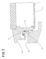
- Fig. 2 is a main structure fragmentary sectional view in an inner case upper stop point of the invention;
- Fig. 3 is a main structure fragmentary sectional view in an inner case lower stop point of the invention;
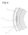
- Fig. 4 is an A-A1 arrow direction sectional view in the inner case lower position of the invention;
- Fig. 5 is a main structure fragmentary sectional view in an inner case upper stop point of the invention;
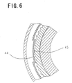
- Fig. 6 is a B-B1 arrow direction sectional view in the inner case upper position of the invention;
- Fig. 7 is a plan view of a ring elastic part of the invention; and
- Fig. 8 is a plan view as viewed in a glass direction of the invention.
-
- An embodiment of the present invention will be explained with reference to the attached drawings.
- The present invention is structured, as shown in Fig. 1, by a degree-
contact step 11, apositioning groove 12 holding a positioningelastic member 5, an outer case 1 having a gear-formed convex/concave portion 13, an outer case degree-contact surface 26, aninner case 2 having apositioning protrusion 25, arotation stop dowel 43 engaged in arotation stop hole 23, and a rotation regulatingring 4 having arotation regulating portion 41 corresponding to the gear-formed concave-convex portion 13 and fixed in theinner case 2. Also, theinner case 2 is mounted with atimepiece movement 9. - Fig. 1 shows a state that an inner
case receiving surface 14 is in contact with an outer case-receivingsurface 21 of theinner case 2, which state is rendered as a lower stop point. Due to a positioningelastic member 5 held by apositioning groove 12 of the outer case 1 and apositioning protrusion 25 of theinner case 2, theinner case 2 can stop at the lower stop point. - By engaging the
rotation stop dowel 43 possessed by the rotation-regulatingring 4 in a singular or plurality ofrotation stop holes 23 opened in theinner case 2, the rotation-regulatingring 4 will not rotate. At this time, engagement is made between the gear-formed concave-convex portion 13 of the outer case 1 and the rotation-regulatingportion 41 of the rotation-regulatingring 4 fixed by theinner case 2, so that theinner case 2 secures stop stability and will not rotate. - The
rotation regulating portion 41 of therotation regulating ring 4 fixed in theinner case 2 is provided singular or in plurality. - The stop stability is further secured for the inner case by the contact between the flatter-preventing
elastic member 6 fitted in afixing groove 24 of theinner case 2 and anelastic contact surface 15 of the outer case 1. - Fig. 2 shows a state that the
inner case 2 is vertically moved from a finger-engaging portion 19 having no outerperipheral wall 16 to a finger-engaging slant surface 28 of the outer case 1 whereby the positioningelastic member 5 held by thepositioning groove 12 of the outer case 1 deforms and gets over apositioning protrusion 25 of theinner case 2. Also, theinner case 2 may be vertically moved by finger-pressing a back-lid bottom surface 71 of theback lid 7. - At this time, the positioning
elastic member 5 held by thepositioning groove 12 of the outer case 1 interferes with a positioning protrusionupper slant surface 27 of theinner case 2 whereby theinner case 2 can stop at an upper stop point and theinner case 2 can be stably rotated in the upper stop point. - In this state, engagement is completely released between the gear-formed concave-
convex portion 13 of the outer case 1 and the rotation-regulatingportion 41 of the rotation-regulatingring 4 fixed on theinner case 2. Theinner case 2 can rotate freely. - The rotation regulating
ring 4 has a removal-preventingprotrusion 42 such that, when theinner case 2 is moved to the upper stop position, therotation regulating ring 4 fixed to theinner case 2 is not left together with the outer case 1 in the lower stop point. By the interference between theremoval preventing protrusion 42 of therotation regulating ring 4 and a circumferential groovelower wall 22, therotation regulating ring 4 is not left in the lower stop point but can be moved together with theinner case 2 to the upper stop point. - In the upper stop point, meshing is made between the gear
concave portion 17 of the gear-formed concave-convex portion 13 of the outer case 1 and a detentelastic protrusion 45 provided in a detentelastic portion 44 of therotation regulating ring 4 fixed in theinner case 2. - If the
inner case 2 is rotated, the detentelastic protrusion 45 provided in the detentelastic portion 44 of therotation regulating ring 4 is moved in a radial direction by a rotation force and intermittently interferes with the gear-formed concave-convex portion 13 formed in the outer case 1, thereby giving click feel to theinner case 2. - The
rotation regulating portion 41 of therotation regulating ring 4 and the detentelastic protrusion 45 are planarly alternately arranged. - Also, the
rotation regulating portion 41 of therotation regulating ring 4 and the detentelastic protrusion 45 are arranged in an upper surface and a lower surface with respect to a planar direction. - The detent
elastic portion 44 of therotation regulating ring 4 and the detentelastic protrusion 45 are singular or in plurality. - The outer case 1 has a degree-
contact step 11 and theinner case 2 has an outer-case-degree-contact portion 26 such that, when theinner case 2 is moved in the upper direction, theinner case 2 is prevented from falling out of the outer case 1. - In this invention, as described above, when the
inner case 2 is positioned in the lower stop position, the gear-formed concave-convex portion 13 engages therotation regulating portion 41 of therotation regulating ring 4 to inhibit theinner case 2 from rotating. When theinner case 2 is positioned in the upper stop position, the gear-formed concave-convex portion 13 and the rotation-regulatingportion 41 of the rotation-regulatingring 4 are released from engagement to enable theinner case 2 to freely rotate. Thus, a wristwatch case structure could have been realized that is different in rotation function of theinner case 2 by the stop positions. - This has made it possible to change the inner case to a desired angle easy to see the timepiece regardless of a wrist position, and lock the rotation of the inner case at that position.
- As shown in Fig. 5 and Fig. 6, in a state the
inner case 2 is moved to the upper stop position, slight interference is caused between the gear-formed concave-convex portion 13 and a detentelastic protrusion 45 provided in the detentelastic portion 44, enabling to provide a click feeling to free rotation of theinner case 2.
Claims (7)
- A wristwatch case comprising:an outer case; andan inner case;wherein the inner case has a structure movable generally vertical with respect to a plane.
- A wristwatch case according to claim 1, further comprising:a rotation-regulating ring having a rotation mechanism on a circumference different in rotation function of the inner case at a plurality of stop points in vertical movable range;wherein the rotation-regulating ring is arranged between the outer case and the inner case.
- A wristwatch case according to claim 1:an inner case having a structure movable generally vertical with respect to a plane ; anda positioning elastic member to stop the inner case in each of a plurality of positions.
- A wristwatch case according to claim 2 ;
wherein the rotation-regulating ring is arbitrary divided the circumference of the rotation regulating ring and alternately arranged a plurality of rotation mechanisms different in the inner case. - A wristwatch case according to claim 4;
wherein the rotation-regulating ring is planarly alternately arranged a plurality of rotation mechanisms different in the inner case. - A wristwatch case according to claim 1, further comprising:a gear-formed concave-convex portion formed in the outer case; anda detent elastic protrusion to interfere with a gear-formed concave-convex portion, to radially move due to a rotation force on the gear-formed concave-convex portion to cause a click feel and to arrange the rotation-regulating ring;wherein the detent elastic protrusion causes a click feel intermittently interfering with the gear-formed concave-convex portion.
- A wristwatch case according to claim 6;
wherein the gear-formed concave-convex portion of the outer case is formed to a planar form of the outer case.
Applications Claiming Priority (2)
| Application Number | Priority Date | Filing Date | Title |
|---|---|---|---|
| JP2000093517A JP2001281359A (en) | 2000-03-30 | 2000-03-30 | Watch case |
| JP2000093517 | 2000-03-30 |
Publications (3)
| Publication Number | Publication Date |
|---|---|
| EP1139186A1 true EP1139186A1 (en) | 2001-10-04 |
| EP1139186A8 EP1139186A8 (en) | 2001-11-28 |
| EP1139186B1 EP1139186B1 (en) | 2005-11-23 |
Family
ID=18608694
Family Applications (1)
| Application Number | Title | Priority Date | Filing Date |
|---|---|---|---|
| EP01302570A Expired - Lifetime EP1139186B1 (en) | 2000-03-30 | 2001-03-20 | Wristwatch case |
Country Status (3)
| Country | Link |
|---|---|
| US (1) | US20010036131A1 (en) |
| EP (1) | EP1139186B1 (en) |
| JP (1) | JP2001281359A (en) |
Cited By (2)
| Publication number | Priority date | Publication date | Assignee | Title |
|---|---|---|---|---|
| EP1835363A1 (en) * | 2006-03-16 | 2007-09-19 | Officine Panerai Branch of Richemont International SA | Timepiece incorporating a rotary bezel |
| CH714976A1 (en) * | 2018-05-14 | 2019-11-15 | Officine Panerai Ag | Watchmaking component comprising rotational locking means. |
Families Citing this family (3)
| Publication number | Priority date | Publication date | Assignee | Title |
|---|---|---|---|---|
| US20070026690A1 (en) * | 2004-11-05 | 2007-02-01 | Yoo Woo S | Selective frequency UV heating of films |
| JP5077333B2 (en) * | 2009-11-30 | 2012-11-21 | カシオ計算機株式会社 | Middle frame member and clock device |
| EP3324250A1 (en) * | 2016-11-16 | 2018-05-23 | The Swatch Group Research and Development Ltd | Device for indicating time zones |
Citations (3)
| Publication number | Priority date | Publication date | Assignee | Title |
|---|---|---|---|---|
| US3785142A (en) * | 1972-03-16 | 1974-01-15 | R Soguel | Watchcase comprising at least a two-piece casing assembly |
| FR2508666A1 (en) * | 1981-06-30 | 1982-12-31 | Bellin Jean Et Pierre | Telescopic mounting for clock - allows winder to disappear from view when clock is withdrawn into elaborate casing |
| US4956827A (en) * | 1987-10-21 | 1990-09-11 | Paolo Spadini | Timepiece |
-
2000
- 2000-03-30 JP JP2000093517A patent/JP2001281359A/en not_active Withdrawn
-
2001
- 2001-03-20 EP EP01302570A patent/EP1139186B1/en not_active Expired - Lifetime
- 2001-03-28 US US09/819,512 patent/US20010036131A1/en not_active Abandoned
Patent Citations (3)
| Publication number | Priority date | Publication date | Assignee | Title |
|---|---|---|---|---|
| US3785142A (en) * | 1972-03-16 | 1974-01-15 | R Soguel | Watchcase comprising at least a two-piece casing assembly |
| FR2508666A1 (en) * | 1981-06-30 | 1982-12-31 | Bellin Jean Et Pierre | Telescopic mounting for clock - allows winder to disappear from view when clock is withdrawn into elaborate casing |
| US4956827A (en) * | 1987-10-21 | 1990-09-11 | Paolo Spadini | Timepiece |
Cited By (4)
| Publication number | Priority date | Publication date | Assignee | Title |
|---|---|---|---|---|
| EP1835363A1 (en) * | 2006-03-16 | 2007-09-19 | Officine Panerai Branch of Richemont International SA | Timepiece incorporating a rotary bezel |
| WO2007105043A3 (en) * | 2006-03-16 | 2008-03-06 | Richemont Int Sa | Timepiece with rotating bezel |
| CH714976A1 (en) * | 2018-05-14 | 2019-11-15 | Officine Panerai Ag | Watchmaking component comprising rotational locking means. |
| EP3570116A1 (en) * | 2018-05-14 | 2019-11-20 | Officine Panerai AG | Clock casing component comprising rotational blocking means |
Also Published As
| Publication number | Publication date |
|---|---|
| EP1139186A8 (en) | 2001-11-28 |
| US20010036131A1 (en) | 2001-11-01 |
| JP2001281359A (en) | 2001-10-10 |
| EP1139186B1 (en) | 2005-11-23 |
Similar Documents
| Publication | Publication Date | Title |
|---|---|---|
| US6599009B2 (en) | Wristwatch case having a rotary bezel | |
| JP6087160B2 (en) | Watch case with orientable index bezel | |
| EP1182521B1 (en) | Wristwatch case with rotary bezel | |
| US11553767B2 (en) | Bayonet mechanism for interchangeable lug and band styles | |
| JP6578975B2 (en) | Clock with rotating bezel | |
| JP2007522461A (en) | Watch crown protector | |
| US6776519B2 (en) | Mysterious rotating bezel | |
| EP1139186B1 (en) | Wristwatch case | |
| JP2018146505A (en) | Rotation device and watch | |
| JP6601664B2 (en) | Rotating operation device and clock | |
| JP2020159719A (en) | Rotation device and watch | |
| JP2017058231A (en) | Lock mechanism of operation member | |
| JP3034210B2 (en) | Rotary switch | |
| JP3810691B2 (en) | Cell phone clock | |
| JP6984635B2 (en) | Switch device and clock | |
| JP2012052919A (en) | Wrist watch | |
| JPH0823592B2 (en) | Rotating bezel structure of watch | |
| JP2000088972A (en) | Pointer clock | |
| JP7493072B1 (en) | clock | |
| JP3063507U (en) | A watch that allows you to set the operating time of the alarm bell on the surface | |
| US5991241A (en) | Timepiece with an alarm time-setting function | |
| JPS6142141Y2 (en) | ||
| JP2010281670A (en) | Watches | |
| RU2314573C2 (en) | Device for automatic browsing of large number of codes by means of one key code | |
| JP2006201052A (en) | clock |
Legal Events
| Date | Code | Title | Description |
|---|---|---|---|
| PUAI | Public reference made under article 153(3) epc to a published international application that has entered the european phase |
Free format text: ORIGINAL CODE: 0009012 |
|
| AK | Designated contracting states |
Kind code of ref document: A1 Designated state(s): AT BE CH CY DE DK ES FI FR GB GR IE IT LI LU MC NL PT SE TR |
|
| AX | Request for extension of the european patent |
Free format text: AL;LT;LV;MK;RO;SI |
|
| RAP1 | Party data changed (applicant data changed or rights of an application transferred) |
Owner name: SEIKO INSTRUMENTS INC. |
|
| 17P | Request for examination filed |
Effective date: 20020307 |
|
| AKX | Designation fees paid |
Free format text: CH FR GB LI |
|
| REG | Reference to a national code |
Ref country code: DE Ref legal event code: 8566 |
|
| GRAP | Despatch of communication of intention to grant a patent |
Free format text: ORIGINAL CODE: EPIDOSNIGR1 |
|
| GRAS | Grant fee paid |
Free format text: ORIGINAL CODE: EPIDOSNIGR3 |
|
| GRAA | (expected) grant |
Free format text: ORIGINAL CODE: 0009210 |
|
| AK | Designated contracting states |
Kind code of ref document: B1 Designated state(s): CH FR GB LI |
|
| REG | Reference to a national code |
Ref country code: GB Ref legal event code: FG4D |
|
| REG | Reference to a national code |
Ref country code: CH Ref legal event code: EP |
|
| REG | Reference to a national code |
Ref country code: CH Ref legal event code: NV Representative=s name: PATENTANWAELTE SCHAAD, BALASS, MENZL & PARTNER AG |
|
| ET | Fr: translation filed | ||
| PLBE | No opposition filed within time limit |
Free format text: ORIGINAL CODE: 0009261 |
|
| STAA | Information on the status of an ep patent application or granted ep patent |
Free format text: STATUS: NO OPPOSITION FILED WITHIN TIME LIMIT |
|
| 26N | No opposition filed |
Effective date: 20060824 |
|
| PGFP | Annual fee paid to national office [announced via postgrant information from national office to epo] |
Ref country code: CH Payment date: 20110314 Year of fee payment: 11 Ref country code: FR Payment date: 20110317 Year of fee payment: 11 |
|
| PGFP | Annual fee paid to national office [announced via postgrant information from national office to epo] |
Ref country code: GB Payment date: 20110316 Year of fee payment: 11 |
|
| REG | Reference to a national code |
Ref country code: CH Ref legal event code: PL |
|
| GBPC | Gb: european patent ceased through non-payment of renewal fee |
Effective date: 20120320 |
|
| REG | Reference to a national code |
Ref country code: FR Ref legal event code: ST Effective date: 20121130 |
|
| PG25 | Lapsed in a contracting state [announced via postgrant information from national office to epo] |
Ref country code: FR Free format text: LAPSE BECAUSE OF NON-PAYMENT OF DUE FEES Effective date: 20120402 Ref country code: CH Free format text: LAPSE BECAUSE OF NON-PAYMENT OF DUE FEES Effective date: 20120331 Ref country code: LI Free format text: LAPSE BECAUSE OF NON-PAYMENT OF DUE FEES Effective date: 20120331 Ref country code: GB Free format text: LAPSE BECAUSE OF NON-PAYMENT OF DUE FEES Effective date: 20120320 |