EP1139124A2 - Long period optical fiber grating filter - Google Patents
Long period optical fiber grating filter Download PDFInfo
- Publication number
- EP1139124A2 EP1139124A2 EP01100523A EP01100523A EP1139124A2 EP 1139124 A2 EP1139124 A2 EP 1139124A2 EP 01100523 A EP01100523 A EP 01100523A EP 01100523 A EP01100523 A EP 01100523A EP 1139124 A2 EP1139124 A2 EP 1139124A2
- Authority
- EP
- European Patent Office
- Prior art keywords
- optical fiber
- refractive index
- long period
- temperature
- wavelength shift
- Prior art date
- Legal status (The legal status is an assumption and is not a legal conclusion. Google has not performed a legal analysis and makes no representation as to the accuracy of the status listed.)
- Ceased
Links
Images




Classifications
-
- G—PHYSICS
- G02—OPTICS
- G02B—OPTICAL ELEMENTS, SYSTEMS OR APPARATUS
- G02B6/00—Light guides; Structural details of arrangements comprising light guides and other optical elements, e.g. couplings
- G02B6/02—Optical fibres with cladding with or without a coating
- G02B6/02057—Optical fibres with cladding with or without a coating comprising gratings
- G02B6/02076—Refractive index modulation gratings, e.g. Bragg gratings
- G02B6/02171—Refractive index modulation gratings, e.g. Bragg gratings characterised by means for compensating environmentally induced changes
- G02B6/02176—Refractive index modulation gratings, e.g. Bragg gratings characterised by means for compensating environmentally induced changes due to temperature fluctuations
- G02B6/0219—Refractive index modulation gratings, e.g. Bragg gratings characterised by means for compensating environmentally induced changes due to temperature fluctuations based on composition of fibre materials
-
- G—PHYSICS
- G02—OPTICS
- G02B—OPTICAL ELEMENTS, SYSTEMS OR APPARATUS
- G02B6/00—Light guides; Structural details of arrangements comprising light guides and other optical elements, e.g. couplings
-
- G—PHYSICS
- G02—OPTICS
- G02B—OPTICAL ELEMENTS, SYSTEMS OR APPARATUS
- G02B6/00—Light guides; Structural details of arrangements comprising light guides and other optical elements, e.g. couplings
- G02B6/02—Optical fibres with cladding with or without a coating
- G02B6/02057—Optical fibres with cladding with or without a coating comprising gratings
- G02B6/02076—Refractive index modulation gratings, e.g. Bragg gratings
- G02B6/0208—Refractive index modulation gratings, e.g. Bragg gratings characterised by their structure, wavelength response
- G02B6/02085—Refractive index modulation gratings, e.g. Bragg gratings characterised by their structure, wavelength response characterised by the grating profile, e.g. chirped, apodised, tilted, helical
- G02B6/02095—Long period gratings, i.e. transmission gratings coupling light between core and cladding modes
-
- G—PHYSICS
- G02—OPTICS
- G02B—OPTICAL ELEMENTS, SYSTEMS OR APPARATUS
- G02B6/00—Light guides; Structural details of arrangements comprising light guides and other optical elements, e.g. couplings
- G02B6/02—Optical fibres with cladding with or without a coating
- G02B6/02057—Optical fibres with cladding with or without a coating comprising gratings
- G02B6/02076—Refractive index modulation gratings, e.g. Bragg gratings
- G02B6/0208—Refractive index modulation gratings, e.g. Bragg gratings characterised by their structure, wavelength response
- G02B6/021—Refractive index modulation gratings, e.g. Bragg gratings characterised by their structure, wavelength response characterised by the core or cladding or coating, e.g. materials, radial refractive index profiles, cladding shape
-
- G—PHYSICS
- G02—OPTICS
- G02B—OPTICAL ELEMENTS, SYSTEMS OR APPARATUS
- G02B6/00—Light guides; Structural details of arrangements comprising light guides and other optical elements, e.g. couplings
- G02B6/02—Optical fibres with cladding with or without a coating
- G02B6/02057—Optical fibres with cladding with or without a coating comprising gratings
- G02B6/02076—Refractive index modulation gratings, e.g. Bragg gratings
- G02B6/02209—Mounting means, e.g. adhesives, casings
-
- G—PHYSICS
- G02—OPTICS
- G02B—OPTICAL ELEMENTS, SYSTEMS OR APPARATUS
- G02B6/00—Light guides; Structural details of arrangements comprising light guides and other optical elements, e.g. couplings
- G02B6/02—Optical fibres with cladding with or without a coating
- G02B6/036—Optical fibres with cladding with or without a coating core or cladding comprising multiple layers
- G02B6/03616—Optical fibres characterised both by the number of different refractive index layers around the central core segment, i.e. around the innermost high index core layer, and their relative refractive index difference
- G02B6/03622—Optical fibres characterised both by the number of different refractive index layers around the central core segment, i.e. around the innermost high index core layer, and their relative refractive index difference having 2 layers only
- G02B6/03633—Optical fibres characterised both by the number of different refractive index layers around the central core segment, i.e. around the innermost high index core layer, and their relative refractive index difference having 2 layers only arranged - -
-
- G—PHYSICS
- G02—OPTICS
- G02B—OPTICAL ELEMENTS, SYSTEMS OR APPARATUS
- G02B6/00—Light guides; Structural details of arrangements comprising light guides and other optical elements, e.g. couplings
- G02B6/02—Optical fibres with cladding with or without a coating
- G02B6/036—Optical fibres with cladding with or without a coating core or cladding comprising multiple layers
- G02B6/03616—Optical fibres characterised both by the number of different refractive index layers around the central core segment, i.e. around the innermost high index core layer, and their relative refractive index difference
- G02B6/03638—Optical fibres characterised both by the number of different refractive index layers around the central core segment, i.e. around the innermost high index core layer, and their relative refractive index difference having 3 layers only
- G02B6/0365—Optical fibres characterised both by the number of different refractive index layers around the central core segment, i.e. around the innermost high index core layer, and their relative refractive index difference having 3 layers only arranged - - +
Definitions
- the present invention relates generally to optical fiber gratings, and in particular, to a temperature-compensated long period optical fiber grating filter.
- An optical fiber grating is typically used as a filter for selecting an optical signal at a particular wavelength traveling along the core of an optical fiber.
- the optical fiber grating removes or reflects light at the particular wavelength by inducing a periodic change in the refractive index inside the optical fiber.
- Such optical fiber gratings are grouped into short period fiber gratings and long period fiber gratings.
- the short period fiber gratings reflect light at a particular wavelength
- the long period fiber gratings couple light from a core mode to a cladding mode.
- long period fiber gratings with a period of tens of micrometers to hundreds of micrometers are used as a gain flattened filter for an erbium doped fiber amplifier (EDFA) because they can remove light at a particular wavelength by coupling light from the core mode to the coupling mode.
- EDFA erbium doped fiber amplifier
- These long period fiber gratings are fabricated by making a periodic change in the refractive index of the photosensitive core of an optical fiber. The refractive index increases in UV (Ultraviolet)-exposed portions and is kept intact in non-exposed portions, so that a periodic refractive index change occurs along the length direction of the optical fiber.
- Light at a particular wavelength is coupled to the cladding mode by determining the difference between the grating period ⁇ and a refractive index difference (n co -n cl (m) ).
- the refractive index difference is readily achieved by appropriately irradiating an optical fiber sensitive to UV light with a UV laser. That is, the optical fiber sensitive to the UV light is covered with a mask with a predetermined grating period ⁇ and the UV laser is projected onto the mask, to thereby increase the refractive index of the core of the photosensitive optical fiber. As the refractive index increases, a coupling wavelength gets longer. For a desired spectrum, that is, desired coupling wavelength and extinction ratio of a long period fiber grating filter device, the UV laser must be projected for an appropriate time with a mask period accurately controlled.
- the coupling wavelength of the thus-fabricated long period fiber gratings is influenced by temperature.
- the shift of the coupling wavelength caused by temperature change is determined by temperature-induced changes of the refractive index and thermal expansion in the length direction of the optical fiber. This relationship is given as where T is temperature.
- d ⁇ (m) /dT is 5-15nm/100°C. Temperature dependency can be decreased by setting d ⁇ (m) /d ⁇ to a negative value or setting d( ⁇ n) (m) /dT to zero.
- the second term of Eq. (3) in the right hand is neglected because it is less than the first term in the right hand by tens of times. For example, the coupling wavelength shifts by 5nm per 100°C in Flexcor 1060 of Corning.
- the refractive index profile of an optical fiber was designed or a grating period was selected such that d ⁇ (m) /d ⁇ in Eq. (3) is a negative value.
- B 2 O 3 was added to make dn/dT of Eq. (3) zero.
- d ⁇ (m) /d ⁇ is a negative value when ⁇ ⁇ 100 ⁇ m by controlling a refractive index in a typical long period fiber filter.
- d( ⁇ n) (m) /dT d(n 01 -n (m) )/dT® d(n core - n SiO2 )/dT d( ⁇ n) (m) /dT can be zero by doping the core with appropriate amounts of GeO 2 (dn Ge /dT > dn Si02 ) and B 2 O 3 (dn B /dT ⁇ dn Si02 /dT).
- the temperature compensation effect is disclosed in detail "Optical Waveguide Grating and Production Method Thereof", EP 0 800 098 A2.
- the present applicant filed an application entitled "A Temperature-Compensated Long Period Fiber Grating Filter Device” for temperature compensation of gratings.
- Two material mechanisms may be considered in selecting a recoating material to be applied around the cladding for temperature-compensated fiber gratings.
- dn/dT of the core is greater than dn/dT of the cladding due to a higher Ge concentration in the core, that is, the coupling peak of long period fiber gratings shifts to a long wavelength as temperature increases.
- the requirement of a recoating material are that its refractive index increases with temperature to thereby induce a short wavelength shift effect with the refractive index of a coating material.
- dn/dT of the core is less than dn/dT of the cladding by adding Ge/B.
- the short wavelength effect takes place in the mode of long period fiber gratings.
- the requirement of a coating material around the cladding is that its refractive index should be increased with temperature, to thereby compensating for the short wavelength shift effects with the long wavelength shift effect of a recoating material.
- the initial refractive index of the coating material around the cladding must be less that the refractive index of the cladding in order to guide both the core mode and the cladding mode.
- a typical recoating material, particularly a polymer experiences thermal expansion as temperature increases. Therefore, when the polymer is recoated on long period gratings written in a general optical fiber, the long wavelength shift effect of the long period fiber gratings is added up to the long wavelength shift effect of the recoating. Hence, it is necessary to use a special recoating material having a refractive index decreased with temperature.
- an object of the present invention to provide a temperature-compensated long period fiber grating filter using a multi-cladding structure.
- a temperature-compensated long period optical fiber grating filter using a multi-cladding structure in an optical fiber used for the temperature-compensated long period optical fiber grating filter, a plurality of long period fiber gratings are formed periodically in a core and the core is doped with a first dopant to show a positive coupling wavelength shift as temperature increases.
- An inner cladding is formed around the core and has a refractive index lower than that of the core.
- An outer cladding is formed around the inner cladding and has a lower refractive index than that of the inner cladding, and is doped with a second dopant to show a negative coupling wavelength shift as the refractive index of the outer cladding is increased with temperature. The positive wavelength shift and the negative wavelength shift are canceled out, thereby compensating temperature.
- a plurality of long period fiber gratings are formed periodically in a core and the core is doped with a first dopant to show a negative coupling wavelength shift as temperature increases.
- An inner cladding is formed around the core and has a refractive index lower than that of the core.
- An outer cladding is formed around the inner cladding and has a lower refractive index than that of the inner cladding, and is doped with a second dopant to show a positive coupling wavelength shift as the refractive index of the outer cladding is increased with temperature. The positive wavelength shift and the negative wavelength shift are canceled out, thereby compensating temperature.
- a predetermined length of a coating is generally peeled from the optical fiber.
- the long period fiber gratings are formed in the coating-free portions.
- FIG. 1 is a perspective view of a packaged optical fiber grating filter
- FIG. 2 is a sectional perspective view of long period fiber gratings in the packaged optical fiber grating filter
- FIG. 3 illustrates a coupling mechanism in the long period optical fiber grating filter.
- the packaged long period optical fiber grating filter includes a core 101 in which long period fiber gratings 105 are written in every predetermined period, a cladding 102 surrounding the core 101, a coating 103 surrounding the cladding 102, and a recoating 104 formed over the long period fiber gratings 105.
- the long period optical fiber grating filter acts as a wavelength dependent attenuator.
- Light traveling in the fundamental guided mode decreases in intensity as it passes through the long period fiber gratings 105, as indicated by arrows that get thinner along the length of the core 101, and Light at the wavelength coupled to the cladding 102 increases in intensity as indicated by arrows that get thicker toward the cladding 102.
- the light at the coupling wavelength increases in intensity along the length direction of the optical fiber after passing through the fiber gratings 105.
- the long period optical fiber grating filter acts as an optical attenuator.
- the refractive index of air, an external factor of the cladding 102 is 1. If the cladding 102 is recoated with a material with refractive index n after the long period fiber gratings 105 are formed, the coupling condition is changed and as a result, the coupling wavelength shifts to a long wavelength or a short wavelength.
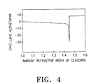
- FIG. 4 is a graph showing the shift of the coupling wavelength with respect to a variation in the ambient refractive index of the cladding.
- a coupling peak shifts as the ambient refractive index changes.
- the coupling wavelength shifts to a short wavelength as the ambient refractive index increases from 1.0.
- the coupling peak disappears when the ambient refractive index equals the refractive index of the cladding. If the ambient refractive index exceeds the refractive index of the cladding, the coupling wavelength shifts to a long wavelength.
- the coupling wavelength shifts to a short wavelength in the region where the external refractive index starting from the refractive index of the air is less than the refractive index of the cladding and to a long wavelength in the region where the ambient refractive index is greater than the refractive index of the cladding.
- the short wavelength shift refers to a negative wavelength shift
- the long wavelength shift refers to a positive wavelength shift.
- the present invention is intended to design an optical fiber profile which can compensate temperature utilizing the above-described property of the long period fiber gratings.
- the present invention is also intended to design an optical fiber which can compensate temperature using a multi-cladding structure.
- FIG. 5 is a graph showing a refractive index variation with respect to a dopant concentration
- FIG. 6 is a graph showing a refractive index variation with respect to the temperature of pure B 2 O 3 .
- a method of compensating temperature by doping a core with B 2 O 3 and GeO 2 is disclosed in detail in "Optical Waveguide Grating and Production Method Thereof', EP 0 800 098 A2.
- only GeO 2 may be used as a dopant or both B 2 O 3 and GeO 2 as dopants for the core.
- the sum of a coupling wavelength shift caused by an increase in refractive index with the amount of GeO 2 and a coupling wavelength shift caused by a decrease in refractive index with the amount of B 2 O 3 is a positive value in the core.
- GeO 2 Only GeO 2 may be used as a dopant or both B 2 O 3 and GeO 2 as dopants for an outer cladding.
- the sum of a coupling wavelength shift caused by an increase in refractive index with the amount of GeO 2 and a coupling wavelength shift caused by a decrease in refractive index with the amount of B 2 O 3 is a negative value in the outer cladding.
- the long period fiber grating filter has a positive wavelength shift, that is, the coupling wavelength shifts to a long wavelength because a core-cladding refractive index difference increases as temperature increases.
- FIG. 7 illustrates an optical fiber refractive index profile of a temperature-compensated long period fiber grating filter according to a preferred embodiment of the present invention.
- an optical fiber includes a core, an inner cladding (primary cladding) surrounding the core, and an outer cladding (secondary cladding) surrounding the inner cladding.
- the diameter of the optical fiber is 125 ⁇ m.
- the refractive index of the outer cladding should be less than that of the inner cladding and the refractive index of the inner cladding should be less than that of the core.
- a positive wavelength shift occurs between the core and the primary cladding and a negative wavelength shift occurs as the ambient refractive index of the secondary cladding changes by doping the core with a dopant, thereby canceling out the positive wavelength shift and the negative wavelength shift.
- the temperature-compensated long period fiber grating filter using a multi-cladding structure will be described in detail. If dn/dT of the core is greater than that of the outer cladding by doping the core with an appropriate amount of Ge or Ge+B, that is, if the coupling wavelength shifts by a positive value as temperature increases, the refractive index of the outer cladding should be less than that of the inner cladding and should increase with temperature.
- the inner cladding is formed of pure silica or silica doped with small amounts of Ge and B. As shown in FIG. 6, as the concentration of B as a dopant increases, a refractive index decreases. Silica is doped with B to design an optical fiber with an outer cladding having a refractive index lower than that of an inner cladding and increased with temperature.
- FIG. 8 illustrates an optical fiber refractive index profile of a temperature-compensated long period fiber grating filter using a multi-cladding structure according to another preferred embodiment of the present invention.
- An optical fiber shown in FIG. 8 has an inner cladding and outer claddings. Once the boundary condition between the inner cladding and the outer claddings, a basic optical fiber structure for temperature compensation is completed. Specifically, the optical fiber has a core, a primary cladding surrounding the core, a secondary cladding surrounding the primary cladding, and a third cladding surrounding the secondary cladding.
- FIG. 9 illustrates the optical fiber refractive index profile of a temperature-compensated long period optical fiber filter device according to a third preferred embodiment of the present invention.
- an optical fiber includes a core, an inner cladding surrounding the core, and an outer cladding surrounding the inner cladding.
- the diameter of the optical fiber is 125 ⁇ m.
- the refractive index of the outer cladding should be less than that of the inner cladding and the refractive index of the inner cladding should be less than that of the core.
- a negative wavelength shift occurs between the core and the primary cladding by doping the core with a dopant and a positive wavelength shift occurs as the ambient refractive index of a doped secondary cladding changes by doping the secondary cladding with a dopant, thereby canceling out the positive wavelength shift and the negative wavelength shift.
- the temperature-compensated long period fiber grating filter using a multi-cladding structure will be described in detail. If dn/dT of the core is less than that of the outer cladding by doping the core with an appropriate amount of Ge or Ge+B, that is, if the coupling wavelength shifts by a negative value as temperature increases, the refractive index of the outer cladding should be less than that of the inner cladding and should decrease with temperature.
- the inner cladding is formed of pure silica or silica doped with a small amount of B or Ge+B. As shown in FIG. 6, as the concentration of B as a dopant increases, a refractive index decreases. Silica is doped with B to design an optical fiber with an outer cladding having a lower refractive index than that of an inner cladding and decreased with temperature.
- FIG. 10 illustrates an optical fiber refractive index profile of a temperature-compensated long period fiber grating filter device using a multi-cladding structure according to a fourth preferred embodiment of the present invention.
- An optical fiber shown in FIG. 10 has an inner cladding and outer claddings. Once the boundary condition between the inner cladding and the outer claddings, a basic optical fiber structure for temperature compensation is completed. Specifically, the optical fiber has a core, a primary cladding surrounding the core, a secondary cladding surrounding the primary cladding, and a third cladding surrounding the secondary cladding. Consequently, the coupling wavelength shifts are canceled out according to the kinds and concentrations of dopants added to the core and the outer cladding, thereby compensating temperature for the long period fiber gratings.
- a novel optical fiber of a multi-cladding structure is designed to be insensitive to an external environment and temperature-compensated. Therefore, the optical fiber is stably used for an optical fiber grating filter without a temperature controller in diverse environments. Furthermore, since a cladding mode is determined by an inner cladding, the overlapping integral between a core mode and the cladding mode is great, a coupling efficiency is high, and thus a coupling mode is readily grown in fabricating long period fiber gratings.
Landscapes
- Physics & Mathematics (AREA)
- General Physics & Mathematics (AREA)
- Optics & Photonics (AREA)
- Diffracting Gratings Or Hologram Optical Elements (AREA)
- Optical Fibers, Optical Fiber Cores, And Optical Fiber Bundles (AREA)
- Light Guides In General And Applications Therefor (AREA)
Abstract
Description

d(δn)(m)/dT can be set to zero by
Claims (12)
- A temperature-compensated long period optical fiber grating filter comprising an optical fiber,
wherein the optical fiber comprises:
a core having a plurality of long period fiber gratings formed periodically and doped with a first dopant to show a positive coupling wavelength shift as temperature increases;
characterized byan inner cladding surrounding the core and having a refractive index lower than that of the core; andan outer cladding surrounding the inner cladding, having a lower refractive index than that of the inner cladding, and doped with a second dopant to show a negative coupling wavelength shift as the refractive index of the outer cladding is increased with temperature,whereby the positive wavelength shift and the negative wavelength shift are canceled out. - The temperature-compensated long period optical fiber grating filter of claim 1, wherein the inner cladding is formed of pure silica.
- The temperature-compensated long period optical fiber grating filter of claim 1 or claim 2, wherein the first dopant includes GeO2.
- The temperature-compensated long period optical fiber grating filter of any of the claims 1 to 3, wherein the second dopant includes B2O3.
- The temperature-compensated long period optical fiber grating filter of any of the claims 1 to 4, wherein the first dopant includes GeO2 and B2O3, and the sum of the coupling wavelength shift caused by the refractive index of the core increased with the concentration of GeO2 and the coupling wavelength shift caused by the refractive index of the core decreased with the concentration of B2O3 represents a positive wavelength shift.
- The temperature-compensated long period optical fiber grating filter of any of the claims 1 to 5, wherein the second dopant includes GeO2 and B2O3, and the sum of the coupling wavelength shift caused by the refractive index of the outer cladding increased with the concentration of GeO2 and the coupling wavelength shift caused by the refractive index of the outer cladding decreased with the concentration of B2O3 represents a negative wavelength shift.
- A temperature- compensated long period optical fiber grating filter comprising an optical fiber,
wherein the optical fiber comprises:
a core having a plurality of long period fiber gratings formed periodically and doped with a first dopant to show a negative coupling wavelength shift as temperature increases;
characterized byan inner cladding surrounding the core and having a refractive index lower than that of the core; andan outer cladding surrounding the inner cladding, having a lower refractive index than that of the inner cladding, and doped with a second dopant to show a positive coupling wavelength shift as the refractive index of the outer cladding is increased with temperature,whereby the positive wavelength shift and the negative wavelength shift are cancelled out. - The temperature-compensated long period optical fiber grating filter of claim 7, wherein the inner cladding is formed of pure silica.
- The temperature-compensated long period optical fiber grating filter of claim 7 or claim 8, wherein the first dopant includes GeO2.
- The temperature-compensated long period optical fiber grating filter of any of the claims 7 to 9, wherein the second dopant includes B2O3.
- The temperature-compensated long period optical fiber grating filter of any of the claims 7 to 10, wherein the first dopant includes GeO2 and B2O3 and the sum of the coupling wavelength shift caused by the refractive index of the core increased with the concentration of GeO2 and the coupling wavelength shift caused by the refractive index of the core decreased with the concentration of B2O3 represents a negative wavelength shift.
- The temperature-compensated long period optical fiber grating filter of any of the claims 7 to 11, wherein the second dopant includes GeO2 and B2O3 and the sum of the coupling wavelength shift caused by the refractive index of the outer cladding increased with the concentration of GeO2 and the coupling wavelength shift caused by the refractive index of the outer cladding decreased with the concentration of B2O3 represents a positive wavelength shift.
Applications Claiming Priority (2)
| Application Number | Priority Date | Filing Date | Title |
|---|---|---|---|
| KR2000000906 | 2000-01-10 | ||
| KR1020000000906A KR100318918B1 (en) | 2000-01-10 | 2000-01-10 | Temperature compensated long period optical fiber grating filter using multi cladding structure |
Publications (2)
| Publication Number | Publication Date |
|---|---|
| EP1139124A2 true EP1139124A2 (en) | 2001-10-04 |
| EP1139124A3 EP1139124A3 (en) | 2004-01-28 |
Family
ID=19637383
Family Applications (1)
| Application Number | Title | Priority Date | Filing Date |
|---|---|---|---|
| EP01100523A Ceased EP1139124A3 (en) | 2000-01-10 | 2001-01-09 | Long period optical fiber grating filter |
Country Status (4)
| Country | Link |
|---|---|
| US (1) | US6463684B2 (en) |
| EP (1) | EP1139124A3 (en) |
| JP (1) | JP2001194539A (en) |
| KR (1) | KR100318918B1 (en) |
Cited By (2)
| Publication number | Priority date | Publication date | Assignee | Title |
|---|---|---|---|---|
| EP1191365A4 (en) * | 1999-01-13 | 2005-04-27 | Sumitomo Electric Industries | DIFFRACTION NETWORK FOR OPTICAL FIBER, CORRESPONDING PRODUCTION PROCESS AND FILTER FOR OPTICAL FIBER |
| EP1316822A4 (en) * | 2000-09-04 | 2005-11-02 | Sumitomo Electric Industries | FIBER OPTIC NETWORK DEVICE |
Families Citing this family (15)
| Publication number | Priority date | Publication date | Assignee | Title |
|---|---|---|---|---|
| WO2002055445A2 (en) * | 2001-01-12 | 2002-07-18 | Corning Incorporated | Optical fiber and preform, method of manufacturing same, and optical component made therefrom |
| JP2003029062A (en) * | 2001-07-13 | 2003-01-29 | Sumitomo Electric Ind Ltd | Optical fiber with built-in grating and optical fiber for forming grating |
| WO2003009011A2 (en) * | 2001-07-20 | 2003-01-30 | Nufern | Optical fiber grating having high temperature insensitivity |
| US7362939B2 (en) | 2001-12-13 | 2008-04-22 | The Furukawa Electric Co., Ltd. | Optical fiber for long period grating, long period grating component and manufacturing method of the same |
| JP2004029691A (en) * | 2002-05-07 | 2004-01-29 | Furukawa Electric Co Ltd:The | Fiber grating type optical components |
| US6904214B2 (en) * | 2002-05-14 | 2005-06-07 | Nufern | Method of providing an optical fiber having a minimum temperature sensitivity at a selected temperature |
| US7064889B2 (en) * | 2002-05-17 | 2006-06-20 | The Board Of Trustees Of The Leland Stanford Junior University | Double-clad fiber lasers and amplifiers having long-period fiber gratings |
| US20040223712A1 (en) * | 2003-04-28 | 2004-11-11 | Ruolin Li | Technique for stabilizing laser wavelength and phase |
| US7116846B2 (en) * | 2004-02-12 | 2006-10-03 | Fibera, Inc. | Athermal fiber Bragg grating |
| US6950578B1 (en) | 2004-05-28 | 2005-09-27 | Fitel Usa Corp. | Highly index-sensitive optical devices including long period fiber gratings |
| US7327907B2 (en) * | 2004-10-14 | 2008-02-05 | Northrop Grumman Corporation | Optical sensor fiber with protective jacketing layers |
| JP2020134722A (en) * | 2019-02-20 | 2020-08-31 | 株式会社フジクラ | Optical devices and laser devices |
| KR102153742B1 (en) * | 2019-11-25 | 2020-09-08 | 한국광기술원 | Optical Fiber Based Voltage Sensor and Voltage Monitoring System Using the Same |
| CN118168587B (en) * | 2024-04-02 | 2025-05-13 | 华中科技大学 | A ring-shaped small-period long-period fiber grating sensor and its preparation method and application |
| WO2026070620A1 (en) * | 2024-09-30 | 2026-04-02 | 住友電気工業株式会社 | Gain-equalizing filter |
Family Cites Families (5)
| Publication number | Priority date | Publication date | Assignee | Title |
|---|---|---|---|---|
| US5703978A (en) * | 1995-10-04 | 1997-12-30 | Lucent Technologies Inc. | Temperature insensitive long-period fiber grating devices |
| US5949934A (en) * | 1996-04-05 | 1999-09-07 | Fujikura, Ltd. | Optical waveguide grating and production method therefor |
| SE510703C2 (en) * | 1996-09-17 | 1999-06-14 | Optisk Forskning Inst | Optical organ and method of such organ |
| US6011886A (en) * | 1997-10-16 | 2000-01-04 | Lucent Technologies Inc. | Recoatable temperature-insensitive long-period gratings |
| AU735273B2 (en) * | 1999-09-09 | 2001-07-05 | Samsung Electronics Co., Ltd. | Long period optical fiber grating filter device |
-
2000
- 2000-01-10 KR KR1020000000906A patent/KR100318918B1/en not_active Expired - Fee Related
- 2000-12-18 JP JP2000384427A patent/JP2001194539A/en active Pending
-
2001
- 2001-01-05 US US09/754,914 patent/US6463684B2/en not_active Expired - Lifetime
- 2001-01-09 EP EP01100523A patent/EP1139124A3/en not_active Ceased
Cited By (2)
| Publication number | Priority date | Publication date | Assignee | Title |
|---|---|---|---|---|
| EP1191365A4 (en) * | 1999-01-13 | 2005-04-27 | Sumitomo Electric Industries | DIFFRACTION NETWORK FOR OPTICAL FIBER, CORRESPONDING PRODUCTION PROCESS AND FILTER FOR OPTICAL FIBER |
| EP1316822A4 (en) * | 2000-09-04 | 2005-11-02 | Sumitomo Electric Industries | FIBER OPTIC NETWORK DEVICE |
Also Published As
| Publication number | Publication date |
|---|---|
| KR100318918B1 (en) | 2002-01-04 |
| KR20010068798A (en) | 2001-07-23 |
| JP2001194539A (en) | 2001-07-19 |
| US6463684B2 (en) | 2002-10-15 |
| EP1139124A3 (en) | 2004-01-28 |
| US20020122624A1 (en) | 2002-09-05 |
Similar Documents
| Publication | Publication Date | Title |
|---|---|---|
| EP1139124A2 (en) | Long period optical fiber grating filter | |
| Vengsarkar et al. | Long-period fiber gratings as band-rejection filters | |
| Shima et al. | A novel temperature-insensitive long-period fiber grating using a boron-codoped-germanosilicate-core fiber | |
| Hill et al. | Fiber Bragg grating technology fundamentals and overview | |
| EP1191365A1 (en) | Optical fiber grating element, production method thereof and optical fiber filter | |
| EP0849231B1 (en) | Athermalized codoped optical waveguide device | |
| EP0800098B1 (en) | Optical waveguide grating and production method therefor | |
| US6522810B2 (en) | Optical loss filter | |
| US6845202B2 (en) | Optical fiber maximizing residual mechanical stress | |
| US6314222B1 (en) | Long-period optical fiber grating filter device | |
| ITMI992378A1 (en) | LONG-TERM OPTICAL FIBER RETICLE FILTER DEVICE | |
| US6198868B1 (en) | Temperature compensated long period optical fiber grating filter | |
| US6317538B1 (en) | Optical waveguide device and optical device having long-period grating | |
| Han et al. | Resonance peak shift and dual peak separation of long-period fiber gratings for sensing applications | |
| EP1054274A1 (en) | Optical waveguide grating and method of manufacturing the same | |
| EP1191374A2 (en) | Long period fiber grating package | |
| Ramachandran et al. | Record bandwidth, spectrally flat coupling with microbend gratings in dispersion-tailored fibers | |
| KR100334801B1 (en) | Long period optical fiber grating filter device | |
| JP4002135B2 (en) | Fiber grating type optical components | |
| RU2173866C2 (en) | Filter based on fiber-optical diffraction gratings with large periods | |
| Chung et al. | New compensation method for temperature sensitivity of fiber Brags grating using Bi-metal | |
| Mizunami et al. | Long-period fiber gratings and their sensing applications | |
| Hill | Fiber bragg gratings | |
| JP2003029063A (en) | Optical fiber grating | |
| Shin et al. | Highly sensitive strain and bending sensor based on a fiber Mach-Zehnder interferometer in photonic crystal fiber |
Legal Events
| Date | Code | Title | Description |
|---|---|---|---|
| PUAI | Public reference made under article 153(3) epc to a published international application that has entered the european phase |
Free format text: ORIGINAL CODE: 0009012 |
|
| 17P | Request for examination filed |
Effective date: 20010109 |
|
| AK | Designated contracting states |
Kind code of ref document: A2 Designated state(s): AT BE CH CY DE DK ES FI FR GB GR IE IT LI LU MC NL PT SE TR |
|
| AX | Request for extension of the european patent |
Free format text: AL;LT;LV;MK;RO;SI |
|
| PUAL | Search report despatched |
Free format text: ORIGINAL CODE: 0009013 |
|
| AK | Designated contracting states |
Kind code of ref document: A3 Designated state(s): AT BE CH CY DE DK ES FI FR GB GR IE IT LI LU MC NL PT SE TR |
|
| AX | Request for extension of the european patent |
Extension state: AL LT LV MK RO SI |
|
| 17Q | First examination report despatched |
Effective date: 20040319 |
|
| AKX | Designation fees paid |
Designated state(s): DE FR GB |
|
| STAA | Information on the status of an ep patent application or granted ep patent |
Free format text: STATUS: THE APPLICATION HAS BEEN REFUSED |
|
| 18R | Application refused |
Effective date: 20070412 |