EP1139043A2 - Device for the passage of pipes from a cabinet to a door of an electrical appliance - Google Patents
Device for the passage of pipes from a cabinet to a door of an electrical appliance Download PDFInfo
- Publication number
- EP1139043A2 EP1139043A2 EP01201017A EP01201017A EP1139043A2 EP 1139043 A2 EP1139043 A2 EP 1139043A2 EP 01201017 A EP01201017 A EP 01201017A EP 01201017 A EP01201017 A EP 01201017A EP 1139043 A2 EP1139043 A2 EP 1139043A2
- Authority
- EP
- European Patent Office
- Prior art keywords
- door
- cabinet
- pipe
- electrical appliance
- passage
- Prior art date
- Legal status (The legal status is an assumption and is not a legal conclusion. Google has not performed a legal analysis and makes no representation as to the accuracy of the status listed.)
- Withdrawn
Links
- 230000008878 coupling Effects 0.000 claims abstract description 3
- 238000010168 coupling process Methods 0.000 claims abstract description 3
- 238000005859 coupling reaction Methods 0.000 claims abstract description 3
- XLYOFNOQVPJJNP-UHFFFAOYSA-N water Substances O XLYOFNOQVPJJNP-UHFFFAOYSA-N 0.000 claims description 20
- 238000001914 filtration Methods 0.000 description 4
- 238000005187 foaming Methods 0.000 description 2
- 230000008014 freezing Effects 0.000 description 2
- 238000007710 freezing Methods 0.000 description 2
- 239000000126 substance Substances 0.000 description 2
- ZAMOUSCENKQFHK-UHFFFAOYSA-N Chlorine atom Chemical compound [Cl] ZAMOUSCENKQFHK-UHFFFAOYSA-N 0.000 description 1
- 238000009825 accumulation Methods 0.000 description 1
- 238000006243 chemical reaction Methods 0.000 description 1
- 229910052801 chlorine Inorganic materials 0.000 description 1
- 239000000460 chlorine Substances 0.000 description 1
- 230000003247 decreasing effect Effects 0.000 description 1
- 230000003467 diminishing effect Effects 0.000 description 1
- 239000003651 drinking water Substances 0.000 description 1
- 235000020188 drinking water Nutrition 0.000 description 1
- 230000008030 elimination Effects 0.000 description 1
- 238000003379 elimination reaction Methods 0.000 description 1
- 150000002894 organic compounds Chemical class 0.000 description 1
- 238000005057 refrigeration Methods 0.000 description 1
Images

Classifications
-
- F—MECHANICAL ENGINEERING; LIGHTING; HEATING; WEAPONS; BLASTING
- F25—REFRIGERATION OR COOLING; COMBINED HEATING AND REFRIGERATION SYSTEMS; HEAT PUMP SYSTEMS; MANUFACTURE OR STORAGE OF ICE; LIQUEFACTION SOLIDIFICATION OF GASES
- F25D—REFRIGERATORS; COLD ROOMS; ICE-BOXES; COOLING OR FREEZING APPARATUS NOT OTHERWISE PROVIDED FOR
- F25D23/00—General constructional features
- F25D23/06—Walls
- F25D23/065—Details
-
- F—MECHANICAL ENGINEERING; LIGHTING; HEATING; WEAPONS; BLASTING
- F25—REFRIGERATION OR COOLING; COMBINED HEATING AND REFRIGERATION SYSTEMS; HEAT PUMP SYSTEMS; MANUFACTURE OR STORAGE OF ICE; LIQUEFACTION SOLIDIFICATION OF GASES
- F25D—REFRIGERATORS; COLD ROOMS; ICE-BOXES; COOLING OR FREEZING APPARATUS NOT OTHERWISE PROVIDED FOR
- F25D23/00—General constructional features
- F25D23/02—Doors; Covers
- F25D23/028—Details
-
- E—FIXED CONSTRUCTIONS
- E05—LOCKS; KEYS; WINDOW OR DOOR FITTINGS; SAFES
- E05D—HINGES OR SUSPENSION DEVICES FOR DOORS, WINDOWS OR WINGS
- E05D11/00—Additional features or accessories of hinges
- E05D11/0081—Additional features or accessories of hinges for transmitting energy, e.g. electrical cable routing
-
- E—FIXED CONSTRUCTIONS
- E05—LOCKS; KEYS; WINDOW OR DOOR FITTINGS; SAFES
- E05D—HINGES OR SUSPENSION DEVICES FOR DOORS, WINDOWS OR WINGS
- E05D5/00—Construction of single parts, e.g. the parts for attachment
- E05D5/02—Parts for attachment, e.g. flaps
- E05D5/08—Parts for attachment, e.g. flaps of cylindrical shape
-
- E—FIXED CONSTRUCTIONS
- E05—LOCKS; KEYS; WINDOW OR DOOR FITTINGS; SAFES
- E05D—HINGES OR SUSPENSION DEVICES FOR DOORS, WINDOWS OR WINGS
- E05D7/00—Hinges or pivots of special construction
- E05D7/08—Hinges or pivots of special construction for use in suspensions comprising two spigots placed at opposite edges of the wing, especially at the top and the bottom, e.g. trunnions
- E05D7/081—Hinges or pivots of special construction for use in suspensions comprising two spigots placed at opposite edges of the wing, especially at the top and the bottom, e.g. trunnions the pivot axis of the wing being situated near one edge of the wing, especially at the top and bottom, e.g. trunnions
-
- E—FIXED CONSTRUCTIONS
- E05—LOCKS; KEYS; WINDOW OR DOOR FITTINGS; SAFES
- E05Y—INDEXING SCHEME ASSOCIATED WITH SUBCLASSES E05D AND E05F, RELATING TO CONSTRUCTION ELEMENTS, ELECTRIC CONTROL, POWER SUPPLY, POWER SIGNAL OR TRANSMISSION, USER INTERFACES, MOUNTING OR COUPLING, DETAILS, ACCESSORIES, AUXILIARY OPERATIONS NOT OTHERWISE PROVIDED FOR, APPLICATION THEREOF
- E05Y2800/00—Details, accessories and auxiliary operations not otherwise provided for
- E05Y2800/10—Additional functions
-
- E—FIXED CONSTRUCTIONS
- E05—LOCKS; KEYS; WINDOW OR DOOR FITTINGS; SAFES
- E05Y—INDEXING SCHEME ASSOCIATED WITH SUBCLASSES E05D AND E05F, RELATING TO CONSTRUCTION ELEMENTS, ELECTRIC CONTROL, POWER SUPPLY, POWER SIGNAL OR TRANSMISSION, USER INTERFACES, MOUNTING OR COUPLING, DETAILS, ACCESSORIES, AUXILIARY OPERATIONS NOT OTHERWISE PROVIDED FOR, APPLICATION THEREOF
- E05Y2900/00—Application of doors, windows, wings or fittings thereof
- E05Y2900/20—Application of doors, windows, wings or fittings thereof for furniture, e.g. cabinets
-
- E—FIXED CONSTRUCTIONS
- E05—LOCKS; KEYS; WINDOW OR DOOR FITTINGS; SAFES
- E05Y—INDEXING SCHEME ASSOCIATED WITH SUBCLASSES E05D AND E05F, RELATING TO CONSTRUCTION ELEMENTS, ELECTRIC CONTROL, POWER SUPPLY, POWER SIGNAL OR TRANSMISSION, USER INTERFACES, MOUNTING OR COUPLING, DETAILS, ACCESSORIES, AUXILIARY OPERATIONS NOT OTHERWISE PROVIDED FOR, APPLICATION THEREOF
- E05Y2900/00—Application of doors, windows, wings or fittings thereof
- E05Y2900/30—Application of doors, windows, wings or fittings thereof for domestic appliances
- E05Y2900/31—Application of doors, windows, wings or fittings thereof for domestic appliances for refrigerators
-
- F—MECHANICAL ENGINEERING; LIGHTING; HEATING; WEAPONS; BLASTING
- F25—REFRIGERATION OR COOLING; COMBINED HEATING AND REFRIGERATION SYSTEMS; HEAT PUMP SYSTEMS; MANUFACTURE OR STORAGE OF ICE; LIQUEFACTION SOLIDIFICATION OF GASES
- F25D—REFRIGERATORS; COLD ROOMS; ICE-BOXES; COOLING OR FREEZING APPARATUS NOT OTHERWISE PROVIDED FOR
- F25D23/00—General constructional features
- F25D23/12—Arrangements of compartments additional to cooling compartments; Combinations of refrigerators with other equipment, e.g. stove
- F25D23/126—Water cooler
-
- F—MECHANICAL ENGINEERING; LIGHTING; HEATING; WEAPONS; BLASTING
- F25—REFRIGERATION OR COOLING; COMBINED HEATING AND REFRIGERATION SYSTEMS; HEAT PUMP SYSTEMS; MANUFACTURE OR STORAGE OF ICE; LIQUEFACTION SOLIDIFICATION OF GASES
- F25D—REFRIGERATORS; COLD ROOMS; ICE-BOXES; COOLING OR FREEZING APPARATUS NOT OTHERWISE PROVIDED FOR
- F25D2400/00—General features of, or devices for refrigerators, cold rooms, ice-boxes, or for cooling or freezing apparatus not covered by any other subclass
- F25D2400/40—Refrigerating devices characterised by electrical wiring
Definitions
- the present invention refers to a device for the passage of pipes from a cabinet to a door of an electrical appliance, in particular for a refrigerator provided with a device dispensing cool water into the outside.
- refrigerator appliances provided with devices for the dispensing of water coming from an external water network.
- a circuit for the connection with an external water network is provided and a hydraulic circuit internal to the refrigerator appliance that is suitable to take the water up to a tank internal to the heat-insulated case of the refrigerator; a tap connected with the aforesaid tank provides to the output of water.
- scope of the present invention is to present a device for the passage of pipes from a cabinet to door of an electrical appliance which solves the aforesaid problems.
- a device for the passage of a pipe from a cabinet to a door of an electrical appliance said door being rotatable as regards a vertical axis, characterized in that it comprises a round housing internal to said door for the passage of the pipe, a hinge for the coupling of the cabinet to the door, said hinge being provided with a tubular duct associated with said housing of the pipe and coaxial to it in such a way that the tubular duct axis corresponds to the rotation axis of the door as regards the cabinet of the electrical appliance.
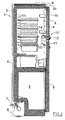
- the refrigerator comprises in a way known per se a cabinet 1 that encloses within itself a heat-insulated case 2 and, on the bottom of the same, a freezing cell 3.
- the heat-insulated case 2 and the freezing cell 3 are frontally open and they are provided with doors 4 and 5 that are hinged to the cabinet 1 in order to be revolving around a vertical axis.
- On the back of the case 2 a condenser and a compressor are provided that are part of a traditional system of refrigeration not visible in the figures.
- the refrigerator is provided with a water inlet 7, directly connectable with the house water network.
- Valve devices 8 preferably associated with a liter-counter not visible in the figure are associated with the water inlet 7.
- a duct for the transport of water 9 that is housed in a back interspace of the cabinet 1, goes up to the top of the cabinet 1, continues in a top interspace of the cabinet 1 towards the front part of the same, passes through the door 4 and ends in a water accumulation tank 10 destined to contain a drinking water reserve.
- the tank 10 is mounted onto the internal wall of the door 4 as a bracket and preferably it has an elongated shape.
- a filtering device 11 is associated with the tank 10 that is suitable to carry out a function of chemical filtering of the water supplied by the water network, for the elimination of possible organic compounds, of products of the reaction of the chlorine present in the water, of substances released by the pipes of the water network.
- the filtering device 11 is part of a dispensing device 12 comprising a tap 13 that takes the filtered water outside. Between the filtering device 11 and the dispensing device 12 second valve means 14 are located.
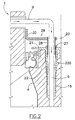
- the door 4 of heat-insulated case 2 is provided with a round sheath 15 on the inside through which the duct 9 and the electrical wires for the solenoid valve 8 and for possible pilot lights located on the top of the refrigerator appliance pass, that are better visible in Figure 2 where only one part of the sheath that slides in the door 4 along the entire length of the duct 9 is shown.
- Said sheath 15 is inserted during the foaming stage of the door 4 without altering the aesthetic profile of said door 4 as compared with the traditional doors for refrigerator.
- the sheath has an internal diameter greater than the external diameter of the duct 9 so that the same duct 9 can be inserted in the sheath 15 with a clearance.
- a device 20 for the passage of the duct 9 from inside the cabinet 1 to the same refrigerator door 4 is provided.
- Said device 20 is made up of a head 21 of the door 4 which is provided with a tubular duct 22 that is inserted in a cavity 22 made on top of the sheath 15 during the foaming stage of the door 4 and better visible in Figures 3 and 4.
- Said tubular duct 22 has a section decreasing from the top toward the bottom and it has an internal octagonal section 23 on the top and a round section 24 on the bottom.
- the head 21 is provided with edges 25 and 26 for its fastening onto the door 4 of the refrigerator.
- a bushing 27 is located that has an octagonal external lateral surface but a rounded internal lateral surface.
- a tubular part 28 of a hinge 29 is arranged that has an L-shape extension 30 for its fastening to the cabinet 1 by means of appropriate screws insertable in holes 31.
- Said tubular part 28 is coaxial to the sheath 5 and to the rotation axis of the door 4 and inside of it the duct 9 and possible electrical wires pass through.
Landscapes
- Engineering & Computer Science (AREA)
- Chemical & Material Sciences (AREA)
- Combustion & Propulsion (AREA)
- Physics & Mathematics (AREA)
- Mechanical Engineering (AREA)
- Thermal Sciences (AREA)
- General Engineering & Computer Science (AREA)
- Hinges (AREA)
- Control Of Vending Devices And Auxiliary Devices For Vending Devices (AREA)
- Refrigerator Housings (AREA)
Abstract
Description
Claims (6)
- Device for the passage of a pipe (9) from a cabinet (1) to a door (4) of an electrical appliance, said door (4) being rotatable as regards a vertical axis, characterized in that it comprises a round housing (15) internal to said door (4) for the passage of the pipe (9), a hinge (29) for the coupling of the cabinet (1) to the door (4), said hinge (29) being provided with a tubular duct (28) associated with said housing (15) of the pipe (9) and coaxial to it in such a way that the axis of said tubular duct (28) corresponds to the rotation axis of the door (4) as regards the cabinet (1) of the electrical appliance.
- Device according to claim 1, characterized in that it comprises a head (21) of the door (4) which is provided with a tubular part (22) connected with said round housing (15) for the passing of the pipe (9), said tubular part (22) partially containing said tubular duct (28) of the hinge (29).
- Device according to claim 2, characterized in that it comprises a bushing (27) between said tubular part (22) of the head (21) and said tubular duct (28) of the hinge (29).
- Device according to claim 1, characterized in that said electrical appliance is a refrigerator with dispenser of cool water (12).
- Device according to claim 4, characterized in that said pipe (9) takes water coming from an external water network to said cool water dispenser (12) located in the refrigerator.
- Device according to claim 1, characterized in that in said round housing (15) of the door (4) electrical wires for pilot lights that are placed on the top of door (4) also pass through.
Applications Claiming Priority (2)
| Application Number | Priority Date | Filing Date | Title |
|---|---|---|---|
| ITMI20000196 IT249765Y1 (en) | 2000-03-31 | 2000-03-31 | DEVICE FOR THE PASSAGE OF PIPES FROM A FURNITURE TO A DOOR OF APPLIANCE |
| ITMI200196U | 2000-03-31 |
Publications (2)
| Publication Number | Publication Date |
|---|---|
| EP1139043A2 true EP1139043A2 (en) | 2001-10-04 |
| EP1139043A3 EP1139043A3 (en) | 2001-11-21 |
Family
ID=11443926
Family Applications (1)
| Application Number | Title | Priority Date | Filing Date |
|---|---|---|---|
| EP01201017A Withdrawn EP1139043A3 (en) | 2000-03-31 | 2001-03-19 | Device for the passage of pipes from a cabinet to a door of an electrical appliance |
Country Status (2)
| Country | Link |
|---|---|
| EP (1) | EP1139043A3 (en) |
| IT (1) | IT249765Y1 (en) |
Cited By (2)
| Publication number | Priority date | Publication date | Assignee | Title |
|---|---|---|---|---|
| WO2007087699A1 (en) * | 2006-02-02 | 2007-08-09 | Whirlpool S.A. | Door hinge for an appliance having a water dispenser and a refrigerating appliance |
| EP2045551A3 (en) * | 2007-10-05 | 2015-04-22 | Liebherr-Hausgeräte Ochsenhausen GmbH | Household device, in particular refrigeration and/or freezer device |
Family Cites Families (3)
| Publication number | Priority date | Publication date | Assignee | Title |
|---|---|---|---|---|
| JPS5948578A (en) * | 1982-09-14 | 1984-03-19 | 株式会社東芝 | Door pivot apparatus of storage housing |
| US4543800A (en) * | 1984-02-16 | 1985-10-01 | White Consolidated Industries, Inc. | Refrigerator door hinge |
| US5941619A (en) * | 1997-09-24 | 1999-08-24 | White Consolidated Industries, Inc. | Electrical connector for a refrigerator and method of installing |
-
2000
- 2000-03-31 IT ITMI20000196 patent/IT249765Y1/en active
-
2001
- 2001-03-19 EP EP01201017A patent/EP1139043A3/en not_active Withdrawn
Cited By (2)
| Publication number | Priority date | Publication date | Assignee | Title |
|---|---|---|---|---|
| WO2007087699A1 (en) * | 2006-02-02 | 2007-08-09 | Whirlpool S.A. | Door hinge for an appliance having a water dispenser and a refrigerating appliance |
| EP2045551A3 (en) * | 2007-10-05 | 2015-04-22 | Liebherr-Hausgeräte Ochsenhausen GmbH | Household device, in particular refrigeration and/or freezer device |
Also Published As
| Publication number | Publication date |
|---|---|
| ITMI20000196V0 (en) | 2000-03-31 |
| IT249765Y1 (en) | 2003-05-28 |
| EP1139043A3 (en) | 2001-11-21 |
| ITMI20000196U1 (en) | 2001-10-01 |
Similar Documents
| Publication | Publication Date | Title |
|---|---|---|
| US11530869B2 (en) | External water-purifying filter case, installation structure thereof and sterilizing method using the same | |
| US4543800A (en) | Refrigerator door hinge | |
| US7415834B2 (en) | In-door water dispenser with door reversibility | |
| CN106813337B (en) | Cooling fan | |
| EP0597680A1 (en) | Refrigerator with door mounted dispenser supply mechanism | |
| US20060017361A1 (en) | Hinge conduit casing | |
| CA2573050A1 (en) | Step-down top hinge for refrigerator door with external dispenser | |
| CN105806009A (en) | Refrigerator | |
| EP2294346A2 (en) | Double-sided door module | |
| KR20060062664A (en) | Refrigerator | |
| CN112074698A (en) | Water path from box body to box door of refrigerator with hinged hinge | |
| EP1139043A2 (en) | Device for the passage of pipes from a cabinet to a door of an electrical appliance | |
| US20220381507A1 (en) | Refrigerator | |
| US20110079037A1 (en) | Refrigerator with treated water system | |
| US10655909B2 (en) | Refrigerating appliance | |
| US8975780B2 (en) | Appliance having an auxiliary power input | |
| US5727772A (en) | Remote valve control device | |
| CN211152559U (en) | Cabinet body for outdoor photoelectric communication | |
| KR200169565Y1 (en) | Door hinge device of refrigerator | |
| EP1624264A1 (en) | Refrigeration apparatus with tubular element | |
| KR102470628B1 (en) | Refrigerator | |
| KR100254625B1 (en) | Door of a refrigerator | |
| FR2923586A1 (en) | WATER SUPPLY OF A WATER DISPENSER PLACED IN A DOOR OF A REFRIGERATION APPARATUS | |
| JP4063778B2 (en) | Storage | |
| WO2001042573A2 (en) | Sanitary units, especially for household use |
Legal Events
| Date | Code | Title | Description |
|---|---|---|---|
| PUAI | Public reference made under article 153(3) epc to a published international application that has entered the european phase |
Free format text: ORIGINAL CODE: 0009012 |
|
| AK | Designated contracting states |
Kind code of ref document: A2 Designated state(s): AT BE CH CY DE DK ES FI FR GB GR IE IT LI LU MC NL PT SE TR |
|
| AX | Request for extension of the european patent |
Free format text: AL;LT;LV;MK;RO;SI |
|
| PUAL | Search report despatched |
Free format text: ORIGINAL CODE: 0009013 |
|
| AK | Designated contracting states |
Kind code of ref document: A3 Designated state(s): AT BE CH CY DE DK ES FI FR GB GR IE IT LI LU MC NL PT SE TR |
|
| AX | Request for extension of the european patent |
Free format text: AL;LT;LV;MK;RO;SI |
|
| AKX | Designation fees paid | ||
| REG | Reference to a national code |
Ref country code: DE Ref legal event code: 8566 |
|
| STAA | Information on the status of an ep patent application or granted ep patent |
Free format text: STATUS: THE APPLICATION IS DEEMED TO BE WITHDRAWN |
|
| 18D | Application deemed to be withdrawn |
Effective date: 20020522 |