EP1139040A1 - Refrigerating device - Google Patents
Refrigerating device Download PDFInfo
- Publication number
- EP1139040A1 EP1139040A1 EP00946326A EP00946326A EP1139040A1 EP 1139040 A1 EP1139040 A1 EP 1139040A1 EP 00946326 A EP00946326 A EP 00946326A EP 00946326 A EP00946326 A EP 00946326A EP 1139040 A1 EP1139040 A1 EP 1139040A1
- Authority
- EP
- European Patent Office
- Prior art keywords
- heat exchanger
- side heat
- electrically driven
- expansion valve
- direct drive
- Prior art date
- Legal status (The legal status is an assumption and is not a legal conclusion. Google has not performed a legal analysis and makes no representation as to the accuracy of the status listed.)
- Granted
Links
Images




Classifications
-
- F—MECHANICAL ENGINEERING; LIGHTING; HEATING; WEAPONS; BLASTING
- F25—REFRIGERATION OR COOLING; COMBINED HEATING AND REFRIGERATION SYSTEMS; HEAT PUMP SYSTEMS; MANUFACTURE OR STORAGE OF ICE; LIQUEFACTION SOLIDIFICATION OF GASES
- F25B—REFRIGERATION MACHINES, PLANTS OR SYSTEMS; COMBINED HEATING AND REFRIGERATION SYSTEMS; HEAT PUMP SYSTEMS
- F25B41/00—Fluid-circulation arrangements
- F25B41/30—Expansion means; Dispositions thereof
- F25B41/31—Expansion valves
- F25B41/34—Expansion valves with the valve member being actuated by electric means, e.g. by piezoelectric actuators
- F25B41/35—Expansion valves with the valve member being actuated by electric means, e.g. by piezoelectric actuators by rotary motors, e.g. by stepping motors
-
- F—MECHANICAL ENGINEERING; LIGHTING; HEATING; WEAPONS; BLASTING
- F25—REFRIGERATION OR COOLING; COMBINED HEATING AND REFRIGERATION SYSTEMS; HEAT PUMP SYSTEMS; MANUFACTURE OR STORAGE OF ICE; LIQUEFACTION SOLIDIFICATION OF GASES
- F25B—REFRIGERATION MACHINES, PLANTS OR SYSTEMS; COMBINED HEATING AND REFRIGERATION SYSTEMS; HEAT PUMP SYSTEMS
- F25B13/00—Compression machines, plants or systems, with reversible cycle
-
- F—MECHANICAL ENGINEERING; LIGHTING; HEATING; WEAPONS; BLASTING
- F25—REFRIGERATION OR COOLING; COMBINED HEATING AND REFRIGERATION SYSTEMS; HEAT PUMP SYSTEMS; MANUFACTURE OR STORAGE OF ICE; LIQUEFACTION SOLIDIFICATION OF GASES
- F25B—REFRIGERATION MACHINES, PLANTS OR SYSTEMS; COMBINED HEATING AND REFRIGERATION SYSTEMS; HEAT PUMP SYSTEMS
- F25B2400/00—Component parts or details not otherwise provided for in this subclass
- F25B2400/12—Inflammable refrigerants
-
- F—MECHANICAL ENGINEERING; LIGHTING; HEATING; WEAPONS; BLASTING
- F25—REFRIGERATION OR COOLING; COMBINED HEATING AND REFRIGERATION SYSTEMS; HEAT PUMP SYSTEMS; MANUFACTURE OR STORAGE OF ICE; LIQUEFACTION SOLIDIFICATION OF GASES
- F25B—REFRIGERATION MACHINES, PLANTS OR SYSTEMS; COMBINED HEATING AND REFRIGERATION SYSTEMS; HEAT PUMP SYSTEMS
- F25B9/00—Compression machines, plants or systems, in which the refrigerant is air or other gas of low boiling point
- F25B9/002—Compression machines, plants or systems, in which the refrigerant is air or other gas of low boiling point characterised by the refrigerant
-
- F—MECHANICAL ENGINEERING; LIGHTING; HEATING; WEAPONS; BLASTING
- F25—REFRIGERATION OR COOLING; COMBINED HEATING AND REFRIGERATION SYSTEMS; HEAT PUMP SYSTEMS; MANUFACTURE OR STORAGE OF ICE; LIQUEFACTION SOLIDIFICATION OF GASES
- F25B—REFRIGERATION MACHINES, PLANTS OR SYSTEMS; COMBINED HEATING AND REFRIGERATION SYSTEMS; HEAT PUMP SYSTEMS
- F25B9/00—Compression machines, plants or systems, in which the refrigerant is air or other gas of low boiling point
- F25B9/002—Compression machines, plants or systems, in which the refrigerant is air or other gas of low boiling point characterised by the refrigerant
- F25B9/006—Compression machines, plants or systems, in which the refrigerant is air or other gas of low boiling point characterised by the refrigerant the refrigerant containing more than one component
-
- Y—GENERAL TAGGING OF NEW TECHNOLOGICAL DEVELOPMENTS; GENERAL TAGGING OF CROSS-SECTIONAL TECHNOLOGIES SPANNING OVER SEVERAL SECTIONS OF THE IPC; TECHNICAL SUBJECTS COVERED BY FORMER USPC CROSS-REFERENCE ART COLLECTIONS [XRACs] AND DIGESTS
- Y02—TECHNOLOGIES OR APPLICATIONS FOR MITIGATION OR ADAPTATION AGAINST CLIMATE CHANGE
- Y02B—CLIMATE CHANGE MITIGATION TECHNOLOGIES RELATED TO BUILDINGS, e.g. HOUSING, HOUSE APPLIANCES OR RELATED END-USER APPLICATIONS
- Y02B30/00—Energy efficient heating, ventilation or air conditioning [HVAC]
- Y02B30/70—Efficient control or regulation technologies, e.g. for control of refrigerant flow, motor or heating
Definitions
- the present invention relates to a refrigerating apparatus, in particular, a refrigerating apparatus provided with a direct drive type electrically driven expansion valve.
- various refrigerating apparatuses including an air conditioner have been provided with a refrigerant circuit including a compressor, a four path switching valve, an external heat exchanger, an expansion valve, and an internal heat exchanger that are connected sequentially in this order, as disclosed in Japanese Laid-Open Patent Publication No. 8-189735.
- a refrigerant circuit including a compressor, a four path switching valve, an external heat exchanger, an expansion valve, and an internal heat exchanger that are connected sequentially in this order, as disclosed in Japanese Laid-Open Patent Publication No. 8-189735.
- the expansion valve a direct drive type electrically driven expansion valve is used.
- a direct drive type electrically driven expansion valve having a predetermined rating torque corresponding to the operational ability, that is the horsepower, has been selected only empirically. Moreover, there has been no consideration about the phenomenon that sludge generated by a refrigerant that contains no chlorine is attached to the driving portion of an electrically driven expansion valve and inhibits the driving, and a necessary torque is determined without considering sludge, and an electrically driven expansion valve having that torque is simply attached.
- a direct drive type electrically driven expansion valve is set by using the friction factor as the parameter.
- the inventors of the present invention examined the conditions for driving the direct drive type electrically driven expansion valve in detail, and discovered that the friction in a thread portion is varied significantly depending on the driving conditions. Then, they made research and found that attachment of sludge is varied with the refrigerant temperature, and the friction factor is varied.
- the direct drive type electrically driven expansion valve is set based on the friction factor on the thread surface at the rating torque (the rating torque equivalent friction factor E in the present invention).
- a first refrigerating apparatus of the present invention includes a low pressure dome type compressor (121), a direct drive type electrically driven expansion valve (Z), a heat source side heat exchanger (123) and a heat application side heat exchanger (131), the heat source side heat exchanger (123) and the heat application side heat exchanger (131) corresponding to each other one-to-one, wherein a refrigerant based on HFC is used, and a rating torque equivalent friction factor E of the direct drive type electrically driven expansion valve (Z) is set to 0.31 or more and less than 0.62.
- a second refrigerating apparatus of the present invention includes a high pressure dome type compressor (121), a direct drive type electrically driven expansion valve (Z), a heat source side heat exchanger (123) and a heat application side heat exchanger (131), the heat source side heat exchanger (123) and the heat application side heat exchanger (131) corresponding to each other one-to-one, , wherein a refrigerant having a discharge temperature in the same level as that of R22 or higher is used, and a rating torque equivalent friction factor E of the direct drive type electrically driven expansion valve (Z) is set to 0.34 or more and less than 0.68.
- a third refrigerating apparatus of the present invention includes a high pressure dome type compressor (121), a direct drive type electrically driven expansion valve (Z), and a heat source side heat exchanger (123) and a heat application side heat exchanger (131), the heat source side heat exchanger (123) and the heat application side heat exchanger (131) corresponding to each other one-to-one, , wherein a refrigerant of R32 alone or a R32 rich mixture comprising an amount of more than 50wt% of R32 is used, and a rating torque equivalent friction factor E of the direct drive type electrically driven expansion valve (Z) is set to 0.37 or more and less than 0.74.
- a fourth refrigerating apparatus of the present invention includes a high pressure dome type compressor (121), a direct drive type electrically driven expansion valve (Z), a heat source side heat exchanger (123) and a heat application side heat exchanger (131), the heat source side heat exchanger (123) and the heat application side heat exchanger (131) corresponding to each other one-to-one, wherein a R32 rich mixture refrigerant having a discharge temperature of more than about 10°C higher than that of R22 is used, and a rating torque equivalent friction factor E of the direct drive type electrically driven expansion valve (Z) is set to 0.37 or more and less than 0.74.
- a fifth refrigerating apparatus of the present invention includes a high pressure dome type compressor (121), a direct drive type electrically driven expansion valve (Z), a heat source side heat exchanger (123) and a heat application side heat exchanger (131), the heat source side heat exchanger (123) and the heat application side heat exchanger (131) corresponding to each other one-to-one, wherein a refrigerant based on HFC is used, and a rating torque equivalent friction factor E of the direct drive type electrically driven expansion valve (Z) is set to 0.37 or more and less than 0.74.
- a sixth refrigerating apparatus of the present invention includes a low pressure dome type compressor (121), a direct drive type electrically driven expansion valve (Z), a heat source side heat exchanger (123) and a heat application side heat exchanger (131), the heat source side heat exchanger (123) and the heat application side heat exchanger (131) corresponding to each other one-to-one, wherein a refrigerant based on HFC is used, and a rating torque equivalent friction factor E of the direct drive type electrically driven expansion valve (Z) is set to 0.62 or more and less than 0.93.
- a seventh refrigerating apparatus of the present invention includes a high pressure dome type compressor (121), a direct drive type electrically driven expansion valve (Z), a heat source side heat exchanger (123) and a heat application side heat exchanger (131), the heat source side heat exchanger (123) and the heat application side heat exchanger (131) corresponding to each other one-to-one, wherein a refrigerant having a discharge temperature in the same level as that of R22 or higher is used, and a rating torque equivalent friction factor E of the direct drive type electrically driven expansion valve (Z) is set to 0.68 or more and less than 1.02.
- An eighth refrigerating apparatus of the present invention includes a high pressure dome type compressor (121), a direct drive type electrically driven expansion valve (Z), a heat source side heat exchanger (123) and a heat application side heat exchanger (131), the heat source side heat exchanger (123) and the heat application side heat exchanger (131) corresponding to each other one-to-one, wherein a refrigerant of R32 alone or a R32 rich mixture comprising an amount of more than 50wt% of R32 is used, and a rating torque equivalent friction factor E of the direct drive type electrically driven expansion valve (Z) is set to 0.74 or more and less than 1.11.
- a ninth refrigerating apparatus of the present invention includes a high pressure dome type compressor (121), a direct drive type electrically driven expansion valve (Z), a heat source side heat exchanger (123) and a heat application side heat exchanger (131), the heat source side heat exchanger (123) and the heat application side heat exchanger (131) corresponding to each other one-to-one, wherein a R32 rich mixture refrigerant having a discharge temperature of more than about 10°C higher than that of R22 is used, and a rating torque equivalent friction factor E of the direct drive type electrically driven expansion valve (Z) is set to 0.74 or more and less than 1.11.
- a tenth refrigerating apparatus of the present invention includes a high pressure dome type compressor (121), a direct drive type electrically driven expansion valve (Z), a heat source side heat exchanger (123) and a heat application side heat exchanger (131), the heat source side heat exchanger (123) and the heat application side heat exchanger (131) corresponding to each other one-to-one, wherein a refrigerant based on HFC is used, and a rating torque equivalent friction factor E of the direct drive type electrically driven expansion valve (Z) is set to 0.74 or more and less than 1.11.
- An eleventh refrigerating apparatus of the present invention includes a low pressure dome type compressor (121), a direct drive type electrically driven expansion valve (Z), a heat source side heat exchanger (123) and a heat application side heat exchanger (131), the heat source side heat exchanger (123) and the heat application side heat exchanger (131) corresponding to each other one-to-one, wherein a refrigerant based on HFC is used, and a rating torque equivalent friction factor E of the direct drive type electrically driven expansion valve (Z) is set to 0.93 or more.
- a twelfth refrigerating apparatus of the present invention includes a high pressure dome type compressor (121), a direct drive type electrically driven expansion valve (Z), a heat source side heat exchanger (123) and a heat application side heat exchanger (131), the heat source side heat exchanger (123) and the heat application side heat exchanger (131) corresponding to each other one-to-one, wherein a refrigerant having a discharge temperature in the same level as that of R22 or higher is used, and a rating torque equivalent friction factor E of the direct drive type electrically driven expansion valve (Z) is set to 1.02 or more.
- a thirteenth refrigerating apparatus of the present invention includes a high pressure dome type compressor (121), a direct drive type electrically driven expansion valve (Z), a heat source side heat exchanger (123) and a heat application side heat exchanger (131), the heat source side heat exchanger (123) and the heat application side heat exchanger (131) corresponding to each other one-to-one, wherein a refrigerant of R32 alone or a R32 rich mixture comprising an amount of more than 50wt% of R32 is used, and a rating torque equivalent friction factor E of the direct drive type electrically driven expansion valve (Z) is set to 1.11 or more.
- a fourteenth refrigerating apparatus of the present invention includes a high pressure dome type compressor (121), a direct drive type electrically driven expansion valve (Z), a heat source side heat exchanger (123) and a heat application side heat exchanger (131), the heat source side heat exchanger (123) and the heat application side heat exchanger (131) corresponding to each other one-to-one, wherein a R32 rich mixture refrigerant having a discharge temperature of more than about 10°C higher than that of R22 is used, and a rating torque equivalent friction factor E of the direct drive type electrically driven expansion valve (Z) is set to 1.11 or more.
- a fifteenth refrigerating apparatus of the present invention includes a high pressure dome type compressor (121), a direct drive type electrically driven expansion valve (Z), a heat source side heat exchanger (123) and a heat application side heat exchanger (131), the heat source side heat exchanger (123) and the heat application side heat exchanger (131) corresponding to each other one-to-one, wherein a refrigerant based on HFC is used, and a rating torque equivalent friction factor E of the direct drive type electrically driven expansion valve (Z) is set to 1.11 or more.
- a sixteenth refrigerating apparatus of the present invention includes a low pressure dome type compressor (121), a direct drive type electrically driven expansion valve (Z), a heat source side heat exchanger (123) and a heat application side heat exchanger (131), one or both of the heat source side heat exchanger (123) and the heat application side heat exchanger (131) being constituted by a plurality of heat exchangers, wherein a refrigerant based on HFC is used, and a rating torque equivalent friction factor E of the direct drive type electrically driven expansion valve (Z) is set to 0.33 or more and less than 0.66.
- a seventeenth refrigerating apparatus of the present invention includes a high pressure dome type compressor (121), a direct drive type electrically driven expansion valve (Z), a heat source side heat exchanger (123) and a heat application side heat exchanger (131), one or both of the heat source side heat exchanger (123) and the heat application side heat exchanger (131) being constituted by a plurality of heat exchangers, wherein a refrigerant having a discharge temperature in the same level as that of R22 or higher is used, and a rating torque equivalent friction factor E of the direct drive type electrically driven expansion valve (Z) is set to 0.40 or more and less than 0.80.
- An eighteenth refrigerating apparatus of the present invention includes a high pressure dome type compressor (121), a direct drive type electrically driven expansion valve (Z), a heat source side heat exchanger (123) and a heat application side heat exchanger (131), one or both of which are constituted by a plurality of heat exchangers, wherein a refrigerant of R32 alone or a R32 rich mixture comprising an amount of more than 50wt% of R32 is used, the rating torque equivalent friction factor E of the direct drive type electrically driven expansion valve (Z) is set to 0.47 or more and less than 0.94.
- a nineteenth refrigerating apparatus of the present invention includes a high pressure dome type compressor (121), the direct drive type electrically driven expansion valve (Z), a heat source side heat exchanger (123) and a heat application side heat exchanger (131), one or both of the heat source side heat exchanger (123) and the heat application side heat exchanger (131) being constituted by a plurality of heat exchangers, wherein a R32 rich mixture refrigerant having a discharge temperature of more than about 10°C higher than that of R22 is used, and a rating torque equivalent friction factor E of the direct drive type electrically driven expansion valve (Z) is set to 0.47 or more and less than 0.94.
- a twentieth refrigerating apparatus of the present invention includes a high pressure dome type compressor (121), a direct drive type electrically driven expansion valve (Z), a heat source side heat exchanger (123) and a heat application side heat exchanger (131), one or both of the heat source side heat exchanger (123) and the heat application side heat exchanger (131) being constituted by a plurality of heat exchangers, wherein a refrigerant based on HFC is used, and a rating torque equivalent friction factor E of the direct drive type electrically driven expansion valve (Z) is set to 0.47 or more and less than 0.94.
- a twenty-first refrigerating apparatus of the present invention includes a low pressure dome type compressor (121), a direct drive type electrically driven expansion valve (Z), a heat source side heat exchanger (123) and a heat application side heat exchanger (131) one or both of which are constituted by a plurality of heat exchangers, wherein a refrigerant based on HFC is used, and a rating torque equivalent friction factor E of the direct drive type electrically driven expansion valve (Z) is set to 0.66 or more and less than 0.99.
- a twenty-second refrigerating apparatus of the present invention includes a high pressure dome type compressor (121) , a direct drive type electrically driven expansion valve (Z), a heat source side heat exchanger (123) and a heat application side heat exchanger (131), one or both of the heat source side heat exchanger (123) and the heat application side heat exchanger (131) being constituted by a plurality of heat exchangers, wherein a refrigerant having a discharge temperature in the same level as that of R22 or higher is used, and a rating torque equivalent friction factor E of the direct drive type electrically driven expansion valve (Z) is set to 0.80 or more and less than 1.20.
- a twenty-third refrigerating apparatus of the present invention includes a high pressure dome type compressor (121), a direct drive type electrically driven expansion valve (Z), a heat source side heat exchanger (123) and a heat application side heat exchanger (131), one or both of the heat source side heat exchanger (123) and the heat application side heat exchanger (131) being constituted by a plurality of heat exchangers, wherein a refrigerant of R32 alone or a R32 rich mixture comprising an amount of more than 50wt% of R32 is used, the rating torque equivalent friction factor E of the direct drive type electrically driven expansion valve (Z) is set to 0.94 or more and less than 1.41.
- a twenty-fourth refrigerating apparatus of the present invention includes a high pressure dome type compressor (121), the direct drive type electrically driven expansion valve (Z), a heat source side heat exchanger (123) and a heat application side heat exchanger (131), one or both of the heat source side heat exchanger (123) and the heat application side heat exchanger (131) being constituted by a plurality of heat exchangers, wherein a R32 rich mixture refrigerant having a discharge temperature of more than about 10°C higher than that of R22 is used, and a rating torque equivalent friction factor E of the direct drive type electrically driven expansion valve (Z) is set to 0.94 or more and less than 1.41.
- a twenty-fifth refrigerating apparatus of the present invention includes a high pressure dome type compressor (121), a direct drive type electrically driven expansion valve (Z), a heat source side heat exchanger (123) and a heat application side heat exchanger (131), one or both of the heat source side heat exchanger (123) and the heat application side heat exchanger (131) being constituted by a plurality of heat exchangers, wherein a refrigerant based on HFC is used, and a rating torque equivalent friction factor E of the direct drive type electrically driven expansion valve (Z) is set to 0.94 or more and less than 1.41.
- a twenty-sixth refrigerating apparatus of the present invention includes a low pressure dome type compressor (121), a direct drive type electrically driven expansion valve (Z), a heat source side heat exchanger (123) and a heat application side heat exchanger (131), one or both of the heat source side heat exchanger (123) and the heat application side heat exchanger (131) being constituted by a plurality of heat exchangers, wherein a refrigerant based on HFC is used, and a rating torque equivalent friction factor E of the direct drive type electrically driven expansion valve (Z) is set to 0.99 or more.
- a twenty-seventh refrigerating apparatus of the present invention includes a high pressure dome type compressor (121), a direct drive type electrically driven expansion valve (Z), a heat source side heat exchanger (123) and a heat application side heat exchanger (131), one or both of the heat source side heat exchanger (123) and the heat application side heat exchanger (131) being constituted by a plurality of heat exchangers, wherein a refrigerant having a discharge temperature in the same level as that of R22 or higher is used, and a rating torque equivalent friction factor E of the direct drive type electrically driven expansion valve (Z) is set to 1.20 or more.
- a twenty-eighth refrigerating apparatus of the present invention includes a high pressure dome type compressor (121), a direct drive type electrically driven expansion valve (Z), a heat source side heat exchanger (123) and a heat application side heat exchanger (131), one or both of the heat source side heat exchanger (123) and the heat application side heat exchanger (131) being constituted by a plurality of heat exchangers, wherein a refrigerant of R32 alone or a R32 rich mixture comprising an amount of more than 50wt% of R32 is used, the rating torque equivalent friction factor E of the direct drive type electrically driven expansion valve (Z) is set to 1.41 or more.
- a twenty-ninth refrigerating apparatus of the present invention includes a high pressure dome type compressor (121), the direct drive type electrically driven expansion valve (Z), a heat source side heat exchanger (123) and a heat application side heat exchanger (131), one or both of the heat source side heat exchanger (123) and the heat application side heat exchanger (131) being constituted by a plurality of heat exchangers, wherein a R32 rich mixture refrigerant having a discharge temperature of more than about 10°C higher than that of R22 is used, and a rating torque equivalent friction factor E of the direct drive type electrically driven expansion valve (Z) is set to 1.41 or more.
- a thirtieth refrigerating apparatus of the present invention includes a high pressure dome type compressor (121), a direct drive type electrically driven expansion valve (Z), a heat source side heat exchanger (123) and a heat application side heat exchanger (131), one or both of the heat source side heat exchanger (123) and the heat application side heat exchanger (131) being constituted by a plurality of heat exchangers, wherein a refrigerant based on HFC is used, and a rating torque equivalent friction factor E of the direct drive type electrically driven expansion valve (Z) is set to 1.41 or more.
- a thirty-first refrigerating apparatus of the present invention performs a vapor compression refrigerating cycle, wherein a direct drive type electrically driven expansion valve (Z) is set based on a rating torque equivalent friction factor E.
- a thirty-second refrigerating apparatus of the present invention includes a compressor (121), a heat source side heat exchanger (123), a direct drive type electrically driven expansion valve (Z), and a heat application side heat exchanger (131), wherein a rating torque equivalent friction factor E of the direct drive type electrically driven expansion valve (Z) is set to 0.31 or more.
- a thirty-third refrigerating apparatus is any one of the first, the second, the sixth, the seventh, the eleventh, the twelfth, the sixteenth, the seventeenth, the twenty-first, the twenty-second, the twenty-sixth, the twenty-seventh, the thirty-first, and the thirty-second refrigerating apparatuses, wherein the refrigerant is R134a.
- a thirty-fourth refrigerating apparatus is any one of the first, the second, the sixth, the seventh, the eleventh, the twelfth, the sixteenth, the seventeenth, the twenty-first, the twenty-second, the twenty-sixth, the twenty-seventh, the thirty-first, and the thirty-second refrigerating apparatuses, wherein the refrigerant is R407C.
- a thirty-fifth refrigerating apparatus is any one of the first, the second, the sixth, the seventh, the eleventh, the twelfth, the sixteenth, the seventeenth, the twenty-first, the twenty-second, the twenty-sixth, the twenty-seventh, the thirty-first, and the thirty-second refrigerating apparatuses, wherein the refrigerant is R410A.
- a thirty-sixth refrigerating apparatus is any one of the first, the second, the sixth, the seventh, the eleventh, the twelfth, the sixteenth, the seventeenth, the twenty-first, the twenty-second, the twenty-sixth, the twenty-seventh, the thirty-first, and the thirty-second refrigerating apparatuses, wherein the refrigerant is R404A or R507A.
- a thirty seventh refrigerating apparatus is any one of the fourth, the ninth, the fourteenth, the nineteenth, the twenty-fourth, the twenty-ninth, the thirty-first, and the thirty-second refrigerating apparatuses, wherein the refrigerant is any one of R32/125 (R32 is at least 70%), R32/134a ( R32 is at least 50%), R32 /propane ( R32 is at least 80%), R32 /butane ( R32 is at least 80%), and R32 /isobutane ( R32 is at least 80%).
- a thirty-eighth refrigerating apparatus is any one of the eleventh to the thirty-second refrigerating apparatuses, and utilizes an existing pipe.
- a thirty-ninth refrigerating apparatus is any one of the first to the thirty-second refrigerating apparatuses, and includes a refrigerating machine oil based on polyvinyl ether.
- a fortieth refrigerating apparatus is any one of the first to the thirty-second refrigerating apparatuses, and includes a refrigerating machine oil based on polyol ester.
- a forty-first refrigerating apparatus is any one of the first the thirty-second refrigerating apparatuses, and includes a refrigerating machine oil based on carbonic acid ester.
- a forty-second refrigerating apparatus is any one of the first the thirty-second refrigerating apparatuses, and includes a refrigerating machine oil based on alkylbenzene.
- a forty-third refrigerating apparatus is any one of the first the thirty-second refrigerating apparatuses, and includes a refrigerating machine oil based on mineral oil.
- a forty-fourth refrigerating apparatus is any one of the first the thirty-second refrigerating apparatuses, and includes a refrigerating machine oil based on polyvinyl ether, polyol ester or carbonic acid ester and mixed with alkylbenzene or mineral oil.
- a forty-fifth refrigerating apparatus is any one of the thirty ninth to the forty-fourth refrigerating apparatuses, wherein an extreme-pressure additive concentration in the refrigerating machine oil is 0.3 or more and 1% by weight or less (refrigerating machine oil weight ratio).
- a forty-sixth refrigerating apparatus is any one of the first to the thirty-second refrigerating apparatuses, wherein the compressor (121) is a swing type compressor.
- a forty-seventh refrigerating apparatus is any one of the first to the thirty-second refrigerating apparatuses, wherein the direct drive type electrically driven expansion valve (Z) includes a valve body (1) including a needle (2), an insert hole (16) of the needle (2), and a refrigerant passage (9) that positioned on one end of the insert hole (16) and whose passage area is adjusted by the needle (2), a case (3) that is attached to the valve body (1) so that the other side of the insert hole (16) is enclosed in an internal space (30), and includes at least a part of electrically driven means (X) for driving the needle (2) in the internal space (30), and flow-rate lowering means (P) for lowering a flow rate of a refrigerant flowing from the refrigerant passage (9) to the internal space (30) through an insert gap (17) formed between the insert hole (16) and the needle (2).
- the direct drive type electrically driven expansion valve (Z) includes a valve body (1) including a needle (2), an insert hole (16) of the needle (2), and a
- a forty-eighth refrigerating apparatus is any one of the first to the thirty-second refrigerating apparatuses, wherein the direct drive type electrically driven expansion valve (Z) includes a valve body (1) including a needle (2), an insert hole (16) of the needle (2), and a refrigerant passage (9) that positioned on one end of the insert hole (16) and whose passage area is adjusted by the needle (2), a case (3) that is attached to the valve body (1) so that the other side of the insert hole (16) is enclosed in an internal space (30), and includes at least a part of electrically driven means (X) for driving the needle (2) in the internal space (30), the electrically driven means (X) having a thread portion that is threaded outside the insert hole (16) and extends in a shaft direction of the insert hole (16), a thread gap (23) in communication with the insert hole (16) on the other side of the insert hole (16), and flow-rate lowering means (Q) for lowering a flow rate of a refrigerant flowing from the refrigerant passage (9) to
- a forty-ninth refrigerating apparatus is any one of the first to the thirty-second refrigerating apparatuses, wherein the direct drive type electrically driven expansion valve (Z) includes a valve body (1) including a needle (2), an insert hole (16) of the needle (2), and a refrigerant passage (9) that positioned on one end of the insert hole (16) and whose passage area is adjusted by the needle (2), a case (3) that is attached to the valve body (1) so that the other side of the insert hole (16) is enclosed in an internal space (30), and includes at least a part of electrically driven means (X) for driving the needle (2) in the internal space (30), an outer circumferential gap (21) formed between an outer circumferential surface of the electrically driven means (X) and an inner circumferential surface of the case (3), and flow-rate lowering means (R) for lowering a flow rate of a refrigerant flowing between a first space (31) positioned on one side of the electrically driven means (X) in the inner space (30) and a second space (32)
- a fiftieth refrigerating apparatus is any one of the first to the thirty-second refrigerating apparatuses, wherein a mixed refrigerant of R32 alone or R32 rich mixture comprising an amount of more than 50wt% of R32 is used, and a permanent magnet (4) of a driving motor (X) of the direct drive type electrically driven expansion valve (Z) is a ferrite magnet
- a fifty-first refrigerating apparatus is any one of the first to the thirty-second refrigerating apparatuses, wherein a permanent magnet (4) of a driving motor (X) of the direct drive type electrically driven expansion valve (Z) is a rare earth magnet.
- a fifty-second refrigerating apparatus is any one of the first to the thirty-second refrigerating apparatuses, wherein a permanent magnet (4) of a driving motor (X) of the direct drive type electrically driven expansion valve (Z) is a rare earth magnet having a demagnetization temperature of 130°C or more.
- a fifty-third refrigerating apparatus is any one of the first to the thirty-second refrigerating apparatuses, wherein a mixed refrigerant of R32 alone or R32 rich mixture comprising an amount of more than 50wt% of R32 is used, and a permanent magnet (4) of a driving motor (X) of the direct drive type electrically driven expansion valve (Z) is a rare earth magnet having a demagnetization temperature of 130°C or more.
- a fifty-fourth refrigerating apparatus is any one of the first to the thirty-second refrigerating apparatuses, wherein a permanent magnet (4) of a driving motor (X) of the direct drive type electrically driven expansion valve (Z) is formed of an anisotropic magnetic material.
- a fifty-fifth refrigerating apparatus is any one of the first to the thirty-second refrigerating apparatuses, wherein a thread surface of the direct drive type electrically driven expansion valve (Z) is coated with a fluorine resin.
- a fifty-sixth refrigerating apparatus is any one of the first to the thirty-second refrigerating apparatuses, wherein a solid lubricant is applied onto a thread surface of the direct drive type electrically driven expansion valve (Z).
- a fifty-seventh refrigerating apparatus is any one of the first to the thirty-second refrigerating apparatuses, and includes a refrigerant circuit (110) including two direct drive type electrically driven expansion valves (Z) arranged in series.
- a fifty eighth refrigerating apparatus is any one of the first to the thirty-second refrigerating apparatuses, and includes a refrigerant circuit (110) including one direct drive type electrically driven expansion valve (Z).
- a fifty-ninth refrigerating apparatus of the present invention includes a low pressure dome type compressor (121), a direct drive type electrically driven expansion valve (Z), a heat source side heat exchanger (123) and a heat application side heat exchanger (131), the heat source side heat exchanger (123) and the heat application side heat exchanger (131) corresponding to each other one-to-one, wherein a refrigerant based on hydrocarbon is used, and a rating torque equivalent friction factor E of the direct drive type electrically driven expansion valve (Z) is set to 0.31 or more and less than 0.62.
- a sixtieth refrigerating apparatus of the present invention includes a high pressure dome type compressor (121), a direct drive type electrically driven expansion valve (Z), a heat source side heat exchanger (123) and a heat application side heat exchanger (131), the heat source side heat exchanger (123) and the heat application side heat exchanger (131) corresponding to each other one-to-one, wherein a refrigerant based on hydrocarbon is used, and a rating torque equivalent friction factor E of the direct drive type electrically driven expansion valve (Z) is set to 0.34 or more and less than 0.68.
- a sixty-first refrigerating apparatus of the present invention includes a low pressure dome type compressor (121), a direct drive type electrically driven expansion valve (Z), a heat source side heat exchanger (123) and a heat application side heat exchanger (131), the heat source side heat exchanger (123) and the heat application side heat exchanger (131) corresponding to each other one-to-one, wherein a refrigerant based on hydrocarbon is used, and a rating torque equivalent friction factor E of the direct drive type electrically driven expansion valve (Z) is set to 0.62 or more and less than 0.93.
- a sixty-second refrigerating apparatus of the present invention includes a high pressure dome type compressor (121), a direct drive type electrically driven expansion valve (Z), a heat source side heat exchanger (123) and a heat application side heat exchanger (131), the heat source side heat exchanger (123) and the heat application side heat exchanger (131) corresponding to each other one-to-one, wherein a refrigerant based on hydrocarbon is used, and a rating torque equivalent friction factor E of the direct drive type electrically driven expansion valve (Z) is set to 0.68 or more and less than 1.02.
- a sixty-third refrigerating apparatus of the present invention includes a low pressure dome type compressor (121), a direct drive type electrically driven expansion valve (Z), a heat source side heat exchanger (123) and a heat application side heat exchanger (131), the heat source side heat exchanger (123) and the heat application side heat exchanger (131) corresponding to each other one-to-one, wherein a refrigerant based on hydrocarbon is used, and a rating torque equivalent friction factor E of the direct drive type electrically driven expansion valve (Z) is set to 0.93 or more.
- a sixty-fourth refrigerating apparatus of the present invention includes a high pressure dome type compressor (121), a direct drive type electrically driven expansion valve (Z), a heat source side heat exchanger (123) and a heat application side heat exchanger (131), the heat source side heat exchanger (123) and the heat application side heat exchanger (131) corresponding to each other one-to-one, wherein a refrigerant based on hydrocarbon is used, and a rating torque equivalent friction factor E of the direct drive type electrically driven expansion valve (Z) is set to 1.02 or more.
- a sixty-fifth refrigerating apparatus of the present invention includes a low pressure dome type compressor (121), a direct drive type electrically driven expansion valve (Z), a heat source side heat exchanger (123) and a heat application side heat exchanger (131), one or both of the heat source side heat exchanger (123) and the heat application side heat exchanger (131) being constituted by a plurality of heat exchangers, wherein a refrigerant based on hydrocarbon is used, and a rating torque equivalent friction factor E of the direct drive type electrically driven expansion valve (Z) is set to 0.33 or more and less than 0.66.
- a sixty-sixth refrigerating apparatus of the present invention includes a high pressure dome type compressor (121), a direct drive type electrically driven expansion valve (Z), a heat source side heat exchanger (123) and a heat application side heat exchanger (131), one or both of the heat source side heat exchanger (123) and the heat application side heat exchanger (131) being constituted by a plurality of heat exchangers, wherein a refrigerant based on hydrocarbon is used, and a rating torque equivalent friction factor E of the direct drive type electrically driven expansion valve (Z) is set to 0.40 or more and less than 0.80.
- a sixty-seventh refrigerating apparatus of the present invention includes a low pressure dome type compressor (121), a direct drive type electrically driven expansion valve (Z), a heat source side heat exchanger (123) and a heat application side heat exchanger (131), one or both of the heat source side heat exchanger (123) and the heat application side heat exchanger (131) being constituted by a plurality of heat exchangers, wherein a refrigerant based on hydrocarbon is used, and a rating torque equivalent friction factor E of the direct drive type electrically driven expansion valve (Z) is set to 0.66 or more and less than 0.99.
- a sixty-eighth refrigerating apparatus of the present invention includes a high pressure dome type compressor (121), a direct drive type electrically driven expansion valve (Z), a heat source side heat exchanger (123) and a heat application side heat exchanger (131), one or both of the heat source side heat exchanger (123) and the heat application side heat exchanger (131) being constituted by a plurality of heat exchangers, wherein a refrigerant based on hydrocarbon is used, and a rating torque equivalent friction factor E of the direct drive type electrically driven expansion valve (Z) is set to 0.80 or more and less than 1.20.
- a sixty-ninth refrigerating apparatus of the present invention includes a low pressure dome type compressor (121), a direct drive type electrically driven expansion valve (Z), a heat source side heat exchanger (123) and a heat application side heat exchanger (131), the heat source side heat exchanger (123) and the heat application side heat exchanger (131) corresponding to each other one-to-one, wherein a refrigerant based on hydrocarbon is used, and a rating torque equivalent friction factor E of the direct drive type electrically driven expansion valve (Z) is set to 0.99 or more.
- a seventieth refrigerating apparatus of the present invention includes a high pressure dome type compressor (121), a direct drive type electrically driven expansion valve (Z), a heat source side heat exchanger (123) and a heat application side heat exchanger (131), one or both of the heat source side heat exchanger (123) and the heat application side heat exchanger (131) being constituted by a plurality of heat exchangers, wherein a refrigerant based on hydrocarbon is used, and a rating torque equivalent friction factor E of the direct drive type electrically driven expansion valve (Z) is set to 1.20 or more.
- a seventy-first refrigerating apparatus of the present invention is any one of the fifty-ninth to the seventieth refrigerating apparatuses, and utilizes an existing pipe.
- a seventy-second refrigerating apparatus of the present invention is any one of the fifty-ninth to the seventieth refrigerating apparatuses, and includes a refrigerating machine oil based on alkylbenzene.
- a seventy-third refrigerating apparatus of the present invention is any one of the fifty-ninth to the seventieth refrigerating apparatuses, and includes a refrigerating machine oil based on mineral oil.
- a seventy-fourth refrigerating apparatus of the present invention is the seventy-second or the seventy-third refrigerating apparatus, wherein an extreme-pressure additive concentration in the refrigerating machine oil is 0.3 or more and 1% by weight or less (refrigerating machine oil weight ratio).
- a seventy-fifth refrigerating apparatus of the present invention is any one of the fifty-ninth to the seventieth refrigerating apparatuses, wherein the compressor (121) is a swing type compressor.
- a seventy-sixth refrigerating apparatus of the present invention is any one of the fifty-ninth to the seventieth refrigerating apparatuses, wherein the direct drive type electrically driven expansion valve (Z) includes a valve body (1) including a needle (2), an insert hole (16) of the needle (2), and a refrigerant passage (9) that positioned on one end of the insert hole (16) and whose passage area is adjusted by the needle (2), a case (3) that is attached to the valve body (1) so that the other side of the insert hole (16) is enclosed in an internal space (30), and includes at least a part of electrically driven means (X) for driving the needle (2) in the internal space (30), and flow-rate lowering means (P) for lowering a flow rate of a refrigerant flowing from the refrigerant passage (9) to the internal space (30) through an insert gap (17) formed between the insert hole (16) and the needle (2).
- the direct drive type electrically driven expansion valve (Z) includes a valve body (1) including a needle (2), an
- a seventy-seventh refrigerating apparatus of the present invention is any one of the fifty-ninth to the seventieth refrigerating apparatuses, wherein the direct drive type electrically driven expansion valve (Z) includes a valve body (1) including a needle (2), an insert hole (16) of the needle (2), and a refrigerant passage (9) that positioned on one end of the insert hole (16) and whose passage area is adjusted by the needle (2), a case (3) that is attached to the valve body (1) so that the other side of the insert hole (16) is enclosed in an internal space (30), and includes at least a part of electrically driven means (X) for driving the needle (2) in the internal space (30), the electrically driven means (X) having a thread portion that is threaded outside the insert hole (16) and extends in a shaft direction of the insert hole (16), a thread gap (23) in communication with the insert hole (16) on the other side of the insert hole (16), and flow-rate lowering means (Q) for lowering a flow rate of a refriger
- a seventy-eighth refrigerating apparatus of the present invention is any one of the fifty-ninth to the seventieth refrigerating apparatuses, wherein the direct drive type electrically driven expansion valve (Z) includes a valve body (1) including a needle (2), an insert hole (16) of the needle (2), and a refrigerant passage (9) that positioned on one end of the insert hole (16) and whose passage area is adjusted by the needle (2), a case (3) that is attached to the valve body (1) so that the other side of the insert hole (16) is enclosed in an internal space (30), and includes at least a part of electrically driven means (X) for driving the needle (2) in the internal space (30), an outer circumferential gap (21) formed between an outer circumferential surface of the electrically driven means (X) and an inner circumferential surface of the case (3), and flow-rate lowering means (R) for lowering a flow rate of a refrigerant flowing between a first space (31) positioned on one side of the electrically driven means (X) in the
- a seventy-ninth refrigerating apparatus of the present invention is any one of the fifty-ninth to the seventieth refrigerating apparatuses, wherein a permanent magnet (4) of a driving motor (X) of the direct drive type electrically driven expansion valve (Z) is a ferrite magnet
- An eightieth refrigerating apparatus of the present invention is any one of the fifty-ninth to the seventieth refrigerating apparatuses, wherein a permanent magnet (4) of a driving motor (X) of the direct drive type electrically driven expansion valve (Z) is a rare earth magnet.
- An eighty-first refrigerating apparatus of the present invention is any one of the fifty-ninth to the seventieth refrigerating apparatuses, wherein a permanent magnet (4) of a driving motor (X) of the direct drive type electrically driven expansion valve (Z) is formed of an anisotropic magnetic material.
- An eighty-second refrigerating apparatus of the present invention is any one of the fifty-ninth to the seventieth refrigerating apparatuses, wherein a thread surface of the direct drive type electrically driven expansion valve (Z) is coated with a fluorine resin.
- An eighty-third refrigerating apparatus of the present invention is any one of the fifty-ninth to the seventieth refrigerating apparatuses, wherein a solid lubricant is applied onto a thread surface of the direct drive type electrically driven expansion valve (Z).
- An eighty-fourth refrigerating apparatus of the present invention is any one of the fifty-ninth to the seventieth refrigerating apparatuses, and includes a refrigerant circuit (110) including two direct drive type electrically driven expansion valves (Z) arranged in series.
- An eighty-fifth refrigerating apparatus of the present invention is any one of the fifty-ninth to the seventieth refrigerating apparatuses, and includes a refrigerant circuit (110) including one direct drive type electrically driven expansion valve (Z).
- the present invention easily can solve the clogging of the direct drive type electrically driven expansion valve (Z), regardless of, for example, the type of refrigerants.
- the present invention provides a totally novel design approach for a driving motor (X) and a thread portion of a direct drive type electrically driven expansion valve (Z), so that the direct drive type electrically driven expansion valve (Z) that can realize reliable driving without wastefulness can be provided.
- the clogging of the direct drive type electrically driven expansion valve (Z) can be prevented in each embodiment of the refrigerant type, the use temperature, the air conditioner capacity and the pair or the multi type.
- the direct drive type electrically driven expansion valve (Z) can be designed very easily. In particular, when other refrigerants such as R32 are used, the direct drive type electrically driven expansion valve (Z) also can be designed very easily.
- the direct drive type electrically driven expansion valve (Z) can be designed in the accordance with the temperature. Therefore, the present invention never fail to solve the problem of clogging of the expansion valve caused by using a single refrigerant of R32 alone or a mixed refrigerant containing a large amount of R32 that increases the discharge temperature and the temperature of the refrigerating machine oil. Furthermore, in a refrigerating apparatus for low temperature in which the discharge temperature is high, the direct drive type electrically driven expansion valve (Z) can be designed very easily.
- the discharge temperature becomes high.
- R32/125 R32 is at least 70%
- R32/134a R32 is at least 50%
- R32 /propane R32 is at least 80%
- R32 /butane R32 is at least 80%
- R32 /isobutane R32 is at least 80%
- the discharge is at least 10°C higher than that of R22.
- optimum design for the direct drive type electrically driven expansion valve (Z) can be achieved very easily.
- a refrigerating apparatus (100) of this embodiment has a configuration of a so-called separate type.
- the refrigerating apparatus (100) includes a refrigerant circuit (110) connecting one external unit (120) that is a unit on the heat source side to one internal unit (130) that is a unit on the heat application side.
- the external unit (120) includes a swing type compressor (121) whose operation frequency is regulated by an inverter, a four path switching valve (122) that switches as shown by the solid line in Fig. 1 in cooling operation cycles and switches as shown by the broken line in Fig. 1 in warming operation cycles, an external heat exchanger (123) as a heat exchanger on the heat source side, that functions as a condenser in cooling operation and as an evaporator in warming operation, a direct drive type electrically driven expansion valve (Z) that constitutes an expansion mechanism to reduce the pressure of a refrigerant.
- a swing type compressor (121) whose operation frequency is regulated by an inverter
- a four path switching valve (122) that switches as shown by the solid line in Fig. 1 in cooling operation cycles and switches as shown by the broken line in Fig. 1 in warming operation cycles
- an external heat exchanger (123) as a heat exchanger on the heat source side, that functions as a condenser in cooling operation and as an evaporator in warming operation
- Z
- the internal unit (130) includes an internal heat exchanger (131) as a heat exchanger on the heat application side that functions as an evaporator at the cooling operation and as a condenser in warming operation.
- the external heat exchanger (123) and the internal heat exchanger (131) are configured to correspond to each other at one-to-one.
- the external heat exchanger (123) is provided with an external fan (120F), and the internal heat exchanger (131) is provided with an internal fan (130F).
- the compressor (121), the four path switching valve (122), the external heat exchanger (123), the direct drive type electrically driven expansion valve (Z), the internal heat exchanger (131) are connected in this order via a refrigerant pipe (140), and the refrigerant circulation circuit (111) is configured as a closed circuit that can operate reversibly by switching the four path switching valve (122) in cooling operation cycles and warming operation cycles to generate heat transfer by the circulation of the refrigerant.
- the direct drive type electrically driven expansion valve (Z) is provided with a valve body (1), a needle (2) and a case (3).
- the valve body (1) is configured as a different diameter member including a passage forming portion (1a) having a large diameter positioned on one side in its shaft direction, a thread forming portion (1c) having a small diameter positioned on the other side, and a shoulder portion (1b) position therebetween.
- the shoulder portion (1b) and the thread forming portion (1c) are inserted in an inner space (30) of the case (3) through an opening (33) formed on one end face of the case (3). In this state, the valve body (1) is integrated with the case (3).
- the passage forming portion (1a) of the valve body (1) is provided with a refrigerant passage (9).
- the refrigerant passage (9) includes a refrigerant inlet portion (11) and a refrigerant outlet portion (12) that are substantially orthogonal, and a valve seat portion (15) is formed on the hem of the refrigerant inlet portion (11).
- a refrigerant inlet pipe (13) is connected to the refrigerant inlet portion (11), and a refrigerant outlet pipe (14) is connected to the refrigerant outlet portion (12).
- a needle insert hole (16) having a predetermined diameter is formed in a portion from the refrigerant passage (9) of the passage forming portion (1a) of the valve body (1) to the end of the thread forming portion (1c).
- One end of the needle insert hole (16) is opened to the refrigerant passage (9), and the other end is opened to the end face of the thread forming portion (1c).
- the needle (2) having a valve head portion (20) at one end is inserted slidably into the needle insert hole (16).
- the needle (2) moves in the shaft direction to increase and decrease the passage area between the valve head portion (20) and the valve seat portion (15). This increase and decrease controls the flow rate of the refrigerant flowing from the refrigerant inlet pipe (13) to the refrigerant outlet pipe (14).
- the valve head portion (20) is seated on the valve seat portion (15) to be closed completely, so that the refrigerant is prevented from flowing.
- the needle (2) is configured as a shaft member with a step including a sliding shaft portion (2a) having a large diameter positioned on the valve head portion (20) side and a supporting shaft portion (2b) having a small diameter.
- the sliding shaft portion (2a) is slidably supported by the needle insert hole (16) so that the position of the shaft center of the sliding shaft portion (2a) is maintained.
- a small needle insert gap (17) is formed between the inner circumferential surface of the needle insert hole (16) and the sliding shaft portion (2a).
- An inner circumferential gap (22) having a larger gap size than the needle insert gap (17) is formed between the inner circumferential surface of the needle hole (16) and the supporting shaft portion (2b).
- a male thread is formed on the outer circumferential surface of the thread forming portion (1c) of the valve body (1).
- a rotor portion (10) constituting a part of a driving motor (X) for driving the needle (2) in the shaft direction is provided in the diameter direction of the thread forming portion (1c).
- the driving motor (X) is configured as a so-called "stepping motor”, and is provided with the rotor portion (10) and an electromagnet (5) disposed on the outer circumference side of the case (3).
- the rotor portion (10) is provided with a thread forming member (7) and a spacer (6).
- the thread forming member (7) is formed as a cylinder having a bottom.
- a female thread engaged in the male thread formed on the thread forming portion (1c) of the valve body (1) is formed on the inner circumferential surface (7a) of the thread forming member (7).
- the spacer (6) is formed as a cylinder having a brim.
- a permanent magnet (4) is held on the outer circumference side of the space (6), and a circumferential wall portion (7a) of the thread forming portion (7) is forcibly engaged and attached on the inner circumference side of the spacer (6).
- the rotor (10) is attached to the valve body (1) by threading the thread forming member (7) to the thread forming portion (1c) of the valve body (1) from the upper side (end portion side).
- the rotor portion (10) is rotated integrally corresponding to the conducting electricity amount (pulse value) of the electromagnetic (5), and moves relatively to the thread forming portion (1c) of the valve body (1) in the shaft direction.
- the rotor portion (10) is coupled to the needle (2) so that the needle (2) moves in the opening and closing direction (i.e., in the shaft direction) by utilizing the movement of the rotor portion (10) in the shaft direction. More specifically, the upper end side of the needle (2) penetrates an end face portion (7b) of the thread forming member (7) and protrudes upward , and a stopping member (34) is provided on the edge of the protrusion so that the needle (2) is prevented from dropping downward. Furthermore, a spring (35) is provided between the lower surface of the end face portion (7b) of the thread forming member (7) and the step portion formed by the sliding shaft portion (2a) and the supporting shaft portion (2b) of the needle (2). The rotor (10) is energized by the spring (35) constantly in the direction in which the stopping member (34) is contacted with the end face portion (7b) of the thread forming member (7).
- the needle (2) increases and decreases the passage area by moving integrally with the rotor portion (10) that moves in the shaft direction in the range up to the seating of the valve head portion (20) onto the valve seat portion (15).
- the rotor (10) moves downward by a predetermined side while shrinking the spring (35), and the force of the spring (35) maintains the valve closing state of the needle (2).
- a predetermined gap is generated between the stopping member (34) and the end face portion (7b) of the. thread forming member (7).
- the gap between the permanent magnet (4) and the inner circumferential surface of the case (3) positioned on the outside of the permanent magnet (4) is set to be small (e.g., about 0.2mm) to hold a proper magnetism effect between the permanent magnet (4) and the electromagnet (5).
- the inner space (30) of the case (3) is segmented into a first space (31) positioned on the lower side and a second space (32) positioned on the upper side by the rotor (10).
- the spaces (31, 32) are in communication with each other via an outer circumferential gap (21) formed between the outer circumferential surface of the permanent magnetic (4) and the inner circumferential surface of the case (3).
- the refrigerant that flows into the needle insert gap (17) goes up through the needle insert gap (17) and further goes up from the needle insert gap (17) through the inner circumferential gap (22) formed between the portion on the other side of the needle (2) and the needle insert hole (16) of the valve body (1). Thereafter, the refrigerant changes its direction and flows down through a thread gap (23) between the thread forming portion (1c) of the valve body (1) and the thread forming member (7) threaded thereto, and reaches the first space (31).
- the refrigerant that flows into the first space (31) goes up through the circumferential gap (21) and flows into the second space (32).
- the flow rate of the refrigerant to the first space (31) and the second space (32) cancels the differential state in both sides of the shaft direction of the rotor portion (10), so that smooth movement of the rotor portion (10) is ensured.
- the needle (2) moves integrally and in cooperation with the movement of the rotor portion (10), so that the refrigerant flow rate is controlled.
- sludge having a high viscosity is generated, for example, from a refrigerating machine oil because of high temperatures due to metallic contact.
- This sludge is circulated in the refrigerant circuit (110) so that the sludge is attached to the needle insert gap (17).
- the attachment of the sludge onto the wall surface of the narrow needle insert gap (17) formed between the needle insert hole (16) provided in the valve body (1) and the needle (2) is prevented as much as possible.
- the refrigerant flows between the refrigerant passage (9) and the inner space (30) on the case (3) side, corresponding to the increase and the decrease of the refrigerant pressure on the refrigerant passage (9) side in response to the operation and the stop of the operation of the compressor (121).
- the attachment of the sludge onto the wall surface of the needle insert gap (17) is suppressed as much as possible by reducing the amount of the refrigerant flowing through the needle insert gap (17).
- a suitable number of refrigerant passages (41) that are means (P) for lowering the flow rate of the refrigerant directly communicating between the refrigerant passage (9) and the first space (31) of the case (3) side without via the needle insert gap (17) are formed in the passage forming portion (1a) of the valve body (1).
- the passage resistance in the refrigerant passage (41) is significantly smaller than that in the needle insert gap (17). Therefore, most of the refrigerant flows through the refrigerant passage (41), and thus the amount of the refrigerant that flows through the needle insert gap (17) is relatively reduced.
- the decrease of the amount of the refrigerant that flows through the needle insert gap (17) reduces the amount of the sludge attached to the wall surface of the needle insert gap (17) by a reduced amount of the refrigerant flowing the needle engage tap (17).
- the interference with the operation of the needle (2) due to the attachment of the sludge having a high viscosity onto the wall surface of the needle insert gap (17) can be prevented as much as possible.
- a proper operation of the needle (2) for example, abnormal liquid compression or superheat of the compressor (121) can be prevented, and the reliability of the refrigerating apparatus (100) in terms of its operation can be enhanced.
- the refrigerant passage (41) Since the refrigerant passage (41) has a large passage area, attachment of sludge hardly occurs in the refrigerant passage (41).
- the refrigerant passage (41) functions as an equalizing hole as well, so that no equalizing hole is not provided.
- the direct drive type electrically driven expansion valve (Z) is set based on the rating torque equivalent friction factor E, which is a feature of the present invention. More specifically, the rating torque equivalent friction factor E of the direct drive type electrically driven expansion valve (Z) is set to 0.31 or more.
- HFC refrigerants contain no chlorine, so that the refrigerants do not have self-lubricating properties.
- the temperature of the metallic contact portion is as high as more than 200°C, so that the refrigerating machine oil or the processed oil left in the inside of the refrigerant circuit (110) is deteriorated, and sludge having a high viscosity is generated.
- the HFC refrigerants are not dissolved with the thus generated sludge.
- the sludge separated from the HFC liquid refrigerant is attached, for example, to the inside of the direct drive type electrically driven expansion valve (Z).
- the direct drive type electrically driven expansion valve (Z) includes the driving motor (X) and the thread portion, in addition to the needle (2).
- the needle (2) is prevented from being driven, so that the refrigerant flow rate cannot be controlled by the direct drive type electrically driven expansion valve (Z).
- the means (P) for lowering the flow rate of the refrigerant is provided in the needle (2).
- the inventors of the present invention conducted a long term durability test of the direct drive type electrically driven expansion valve (Z).
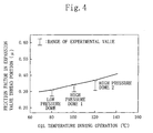
- Figs. 3 and 4 show the results.
- the refrigerant used for the test was R407C.
- Fig. 3 shows the results in the case where a multi air conditioner provided with a plurality of internal units (130), which is not one shown in Fig. 1, is used, and the refrigerant previously contains impurities such as processed oil or water and air.
- Fig. 2 shows the results in the case where a so-called pair air conditioner provided with one external unit (120) and one internal unit (130) is used.
- the amount of the mixed impurities, water and air in the pipe is larger than in the case of the pair air conditioners.
- the amount of the impurities, etc., mixed in the production process or at the time of the installation on the site was measured experimentally. Based on these results, the maximum amount of the impurities or the like when a multi-air conditioner or a pair air conditioner was installed was predicted, and the corresponding amount was mixed in the refrigerating cycle of the refrigerant circuit (110) prior to the test start.
- the operation period is predetermined to correspond to a use term of about 13 years. Since the sludge generation in the inside of the compressor (121) is due to a chemical change, when the temperature of the refrigerating machine oil is high, the generation rate is high. The temperature of the refrigerating machine oil is higher when the compressor (121) is of a high pressure dome type than in the case of a low pressure dome type. This case is shown by high pressure dome 1 in Figs. 3 and 4.
- the oil temperature is about the same level as that of R22. Compared with those cases, in the case of R32 refrigerants, the discharge temperature of the compressor (121) is about 20°C higher. In the case of R32 refrigerants and high pressure dome compressor (121), the oil temperature is about 20°C higher. This case is shown by high pressure dome 1 in Figs. 3 and 4.
- the oil temperature during operation is kept constant so as to evaluate the effect of the oil temperature on the sludge generation.
- the magnitude of the differential pressure that affects the inlet and the output of the direct drive type electrically driven expansion valve (Z) during operation is varied with the refrigerants.
- the differential pressure is varied with the use of the refrigerating apparatus (100) such as one for air conditioning or for low temperature.
- Table 1 shows the differential pressures for each refrigerant and each use of the refrigerating apparatus (100).
- the minimum torque is a minimum value of torque that allows the direct drive type electrically driven expansion valve (Z) to operate without pulse displacement in the pressure range used.
- the torque of the direct drive type electrically driven expansion valve (Z) is ideally measured from the rotor, because an ordinary valve has a structure where the rotor (rotator) is enclosed therein.
- an applied pressure may leak outside.
- the torque of the direct drive type electrically driven expansion valve (Z) is measure in the following manner.
- the minimum torque T of the direct drive type electrically driven expansion valve (Z) can be shown as follows.
- Equation 2 T ( ⁇ ⁇ d 2 /4) ⁇ ⁇ p ⁇ (D/2) ⁇ ( ⁇ /0. 966)
- Equation 3 The minimum torque T, the needle diameter d, the differential pressure ⁇ p , the thread effective diameter D that are measured by the above-described measuring apparatus are substituted in Equation 3.
- the friction factor ⁇ of the thread portion of the direct drive type electrically driven expansion valve (Z) after long durability test can be obtained.
- the vertical axis ⁇ in Figs. 3 and 4 are obtained by Equation 3.
- the value of ⁇ before the test is about 0.2 to 0.3.
- the graphs indicate that as the oil temperature becomes higher, the value of ⁇ becomes higher.
- the characteristics shown in Figs. 3 and 4 are the most distinguished feature of the present invention.
- the friction factor ⁇ becomes higher in the following order: when a low pressure dome type compressor (121) (the low pressure dome of Figs. 3 and 4 ) is used; when a first high pressure dome type compressor (121) (the high pressure dome 1 of Figs. 3 and 4 ) is used; and a second high pressure dome type compressor (121) (the high pressure dome 2 of Figs. 3 and 4) is used.
- the inventors of the present invention noted that the fact that the friction factor ⁇ becomes higher in order conventionally has not been considered at all, and newly found that the direct drive type electrically driven expansion valve (Z) can be selected based on the friction factor ⁇ . This is the most important point.
- T 0 E ⁇ d 2 ⁇ ⁇ p ⁇ D/(2. 461)
- T 0 Rating torque (torque that is generated by the driving motor (X) at a rating voltage)
- E Equivalent friction factor on the thread surface (rating torque equivalent friction factor)
- crank angle A and the lead angle B of the thread are the same as those used in this test, but when they are different, the factor of Equation 5 can be changed based on Equation 1.
- Equation 6 how large the rating torque equivalent friction factor E with respect to the friction factor ⁇ should be depends on how large the safety ratio should be.
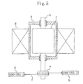
- Fig. 5 shows the outline of a measuring apparatus for measuring the torque.
- a case a of a measuring apparatus is provided with a shaft b that penetrates the case a, and a rotor c attached to the shaft b is provided in the case a.
- a coil d is provided outside of the case a.
- a pulley e is attached to one end of the shaft b, and a first load cell g and a second load cell h are attached to both ends of a string f wound around the pulley e.
- the pull-out torque measurement is as follows.
- the tension of the string f wound around the pulley e is increased while rotating the rotor c at a constant speed. Then the tension is measured by the first load cell g and the second load cell h when the pulley e stops rotating.
- N1 and N2 These values are denoted by N1 and N2 , and the pull-out torque T 1 is calculated based on the following equation.
- T 1
- D Outer diameter of the pulley e d : Outer diameter of the string f
- the average value of the pull-out torque T 1 and the pull-in torque T 2 is defined as the rating torque T 0 .
- the pull-out torque T 1 and the pull-in torque T 2 are in the same level. In such a case, the smaller torque can be defined as the rating torque T 0 for safety. In general, T 1 > T 2 .
- Table 2 shows the rating torque equivalent friction factor E that ensures the reliability of the direct drive type electrically driven expansion valve (Z).
- Pair Multi Threshold Desirable Most desirable Threshold Desirable Most desirable Low pressure dome 0.31 0.62 0.93 0.33 0.66 0.99 High pressure dome 1 0.34 0.68 1.02 0.40 0.80 1.20 High pressure dome 2 (high oil temperature) 0.37 0.74 1.11 0.47 0.94 1.41
- the direct drive type electrically driven expansion valve (Z) is set based on the rating torque equivalent friction factor E.
- the rating torque equivalent friction factor E of the direct drive type electrically driven expansion valve (Z) can be set to 0.31 or more.
- the safety factor is 2 or more, the operation of the direct drive type electrically driven expansion valve (Z) can be maintained. Therefore, it is desirable to set the safety factor to 2 or more to maintain the reliability with respect to various nonuniformity factors.
- the rating torque T 0 necessary for driving is obtained based on the rating torque equivalent friction factor E of Table 2 from Equation 4. If the direct drive type electrically driven expansion valve (Z) or the driving motor (X) is designed in such a manner that this rating torque T 0 is generated, a highly reliable voltage expansion valve easily can be set in accordance with various capacities with various refrigerants.
- an extreme-pressure additive is added to the refrigerating machine oil.
- the extreme-pressure additive is added for the purpose of preventing the sliding portion of the compressor (121) from being burned when metallic contact occurs.
- the additive itself forms sludge, and causes clogging of the expansion valve.
- the added amount is 0.3% or more, the sludge caused by the extreme-pressure additive contributes clogging.
- the added amount is more than 1%, most of the extreme-pressure additive results in sludge.
- the vapor temperature is lower than that of an air conditioning apparatus, and therefore the discharge temperature is higher.
- the high pressure dome type compressor (121) when the discharge temperature is high, the temperature of the refrigerating machine oil is high as well. As a result, a large amount of sludge is generated. Therefore, in such a refrigerating apparatus (100), it is necessary to select the rating torque equivalent friction factor E for the case where the oil temperature of the high pressure dome type compressor (121) is high.
- the permanent magnet (4) of the driving motor (X) may be formed of ferrite or rare earth.
- Rare earth loses magnetism (demagnetization) when it reaches a predetermined temperature or more. Therefore, when a refrigerant having a high discharge temperature such as R32 is used, it is preferable to use ferrite.
- the magnetism of rare earth is larger than that of ferrite, and is characterized by being capable of generating a large torque. Therefore, in the case where the direct drive type electrically driven expansion valve (Z) is used at a temperature that is not increased to high temperature, making the torque large by using a rare earth magnet leads to improvement of the reliability. In the case where a refrigerant having a high temperature such as R32 is used, it is preferable to use a rare earth magnet having a demagnetization temperature of 130°C or more to enhance the heat resistance.
- this embodiment easily can solve clogging of the direct drive type electrically driven expansion valve (Z) regardless of the type of the refrigerant.
- the present invention is directed to a totally new design approach of the driving motor (X) and the thread portion of the direct drive type electrically driven expansion valve (Z), and the direct drive type electrically driven expansion valve (Z) that can realize reliable driving without wastefulness can be provided.
- the direct drive type electrically driven expansion valve (Z) can be designed very easily. In particular, when other refrigerants such as R32 are used, the direct drive type electrically driven expansion valve (Z) also can be designed very easily.
- the direct drive type electrically driven expansion valve (Z) can be designed in the accordance with the temperature. Therefore, the present invention can solve the problem of clogging of the expansion valve caused by using a refrigerant of R32 alone or a mixed refrigerant containing a large amount of R32 that increases the discharge temperature and the temperature of the refrigerating machine oil. Furthermore, in a refrigerating apparatus for low temperature in which the discharge temperature is high, the direct drive type electrically driven expansion valve (Z) can be designed very easily.
- the discharge temperature becomes high.
- R32/125 R32 is at least 70%
- R32/134a R32 is at least 50%
- R32 /propane R32 is at least 80%
- R32 /butane R32 is at least 80%
- R32 /isobutane R32 is at least 80%
- the discharge is more than 10°C higher than that of R22.
- optimum design for the direct drive type electrically driven expansion valve (Z) can be achieved very easily.
- This example is a refrigerating apparatus (100) including the low pressure dome type compressor (121), the direct drive type electrically driven expansion valve (Z), the heat source side heat exchanger (123) and the heat application side heat exchanger (131), the heat source side heat exchanger (123) and the heat application side heat exchanger (131) corresponding to each other one-to-one.
- the rating torque equivalent friction factor E of the direct drive type electrically driven expansion valve (Z) is set to 0.31 or more and less than 0.62.
- This example is a refrigerating apparatus (100) including the high pressure dome type compressor (121), the direct drive type electrically driven expansion valve (Z), the heat source side heat exchanger (123) and the heat application side heat exchanger (131), the heat source side heat exchanger (123) and the heat application side heat exchanger (131) corresponding to each other one-to-one.
- the rating torque equivalent friction factor E of the direct drive type electrically driven expansion valve (Z) is set to 0.34 or more and less than 0.68.
- This example is a refrigerating apparatus (100) including the high pressure dome type compressor (121), the direct drive type electrically driven expansion valve (Z), the heat source side heat exchanger (123) and the heat application side heat exchanger (131), the heat source side heat exchanger (123) and the heat application side heat exchanger (131) corresponding to each other one-to-one.
- the rating torque equivalent friction factor E of the direct drive type electrically driven expansion valve (Z) is set to 0.37 or more and less than 0.74.
- This example is a refrigerating apparatus (100) including the high pressure dome type compressor (121), the direct drive type electrically driven expansion valve (Z), the heat source side heat exchanger (123) and the heat application side heat exchanger (131), the heat source side heat exchanger (123) and the heat application side heat exchanger (131) corresponding to each other one-to-one.
- the rating torque equivalent friction factor E of the direct drive type electrically driven expansion valve (Z) is set to 0.37 or more and less than 0.74.
- This example is a refrigerating apparatus (100) including the high pressure dome type compressor (121), the direct drive type electrically driven expansion valve (Z), the heat source side heat exchanger (123) and the heat application side heat exchanger (131), the heat source side heat exchanger (123) and the heat application side heat exchanger (131) corresponding to each other one-to-one.
- the rating torque equivalent friction factor E of the direct drive type electrically driven expansion valve (Z) is set to 0.37 or more and less than 0.74.
- This example is a refrigerating apparatus (100) including the low pressure dome type compressor (121), the direct drive type electrically driven expansion valve (Z), the heat source side heat exchanger (123) and the heat application side heat exchanger (131), the heat source side heat exchanger (123) and the heat application side heat exchanger (131) corresponding to each other one-to-one.
- the rating torque equivalent friction factor E of the direct drive type electrically driven expansion valve (Z) is set to 0.62 or more and less than 0.93.
- This example is a refrigerating apparatus (100) including the high pressure dome type compressor (121), the direct drive type electrically driven expansion valve (Z), the heat source side heat exchanger (123) and the heat application side heat exchanger (131), the heat source side heat exchanger (123) and the heat application side heat exchanger (131) corresponding to each other one-to-one.
- the rating torque equivalent friction factor E of the direct drive type electrically driven expansion valve (Z) is set to 0.68 or more and less than 1.02.
- This example is a refrigerating apparatus (100) including the high pressure dome type compressor (121), the direct drive type electrically driven expansion valve (Z), the heat source side heat exchanger (123) and the heat application side heat exchanger (131), the heat source side heat exchanger (123) and the heat application side heat exchanger (131) corresponding to each other one-to-one.
- the rating torque equivalent friction factor E of the direct drive type electrically driven expansion valve (Z) is set to 0.74 or more and less than 1.11.
- This example is a refrigerating apparatus (100) including the high pressure dome type compressor (121), the direct drive type electrically driven expansion valve (Z), the heat source side heat exchanger (123) and the heat application side heat exchanger (131), the heat source side heat exchanger (123) and the heat application side heat exchanger (131) corresponding to each other one-to-one.
- the rating torque equivalent friction factor E of the direct drive type electrically driven expansion valve (Z) is set to 0.74 or more and less than 1.11.
- This example is a refrigerating apparatus (100) including the high pressure dome type compressor (121), the direct drive type electrically driven expansion valve (Z), the heat source side heat exchanger (123) and the heat application side heat exchanger (131), the heat source side heat exchanger (123) and the heat application side heat exchanger (131) corresponding to each other one-to-one.
- the rating torque equivalent friction factor E of the direct drive type electrically driven expansion valve (Z) is set to 0.74 or more and less than 1.11.
- This example is a refrigerating apparatus (100) including the low pressure dome type compressor (121), the direct drive type electrically driven expansion valve (Z), the heat source side heat exchanger (123) and the heat application side heat exchanger (131), the heat source side heat exchanger (123) and the heat application side heat exchanger (131) corresponding to each other one-to-one.
- the rating torque equivalent friction factor E of the direct drive type electrically driven expansion valve (Z) is set to 0.93 or more.
- This example is a refrigerating apparatus (100) including the high pressure dome type compressor (121), the direct drive type electrically driven expansion valve (Z), the heat source side heat exchanger (123) and the heat application side heat exchanger (131), the heat source side heat exchanger (123) and the heat application side heat exchanger (131) corresponding to each other one-to-one.
- the rating torque equivalent friction factor E of the direct drive type electrically driven expansion valve (Z) is set to 1.02 or more.
- This example is a refrigerating apparatus (100) including the high pressure dome type compressor (121), the direct drive type electrically driven expansion valve (Z), the heat source side heat exchanger (123) and the heat application side heat exchanger (131), the heat source side heat exchanger (123) and the heat application side heat exchanger (131) corresponding to each other one-to-one.
- the rating torque equivalent friction factor E of the direct drive type electrically driven expansion valve (Z) is set to 1.11 or more.
- This example is a refrigerating apparatus (100) including the high pressure dome type compressor (121), the direct drive type electrically driven expansion valve (Z), the heat source side heat exchanger (123) and the heat application side heat exchanger (131), the heat source side heat exchanger (123) and the heat application side heat exchanger (131) corresponding to each other one-to-one.
- the rating torque equivalent friction factor E of the direct drive type electrically driven expansion valve (Z) is set to 1.11 or more.
- This example is a refrigerating apparatus (100) including the high pressure dome type compressor (121), the direct drive type electrically driven expansion valve (Z), the heat source side heat exchanger (123) and the heat application side heat exchanger (131), the heat source side heat exchanger (123) and the heat application side heat exchanger (131) corresponding to each other one-to-one.
- the rating torque equivalent friction factor E of the direct drive type electrically driven expansion valve (Z) is set to 1.11 or more.
- This example is a refrigerating apparatus (100) including the low pressure dome type compressor (121), the direct drive type electrically driven expansion valve (Z), the heat source side heat exchanger (123) and the heat application side heat exchanger (131), one or both of the heat source side heat exchanger (123) and the heat application side heat exchanger (131) being constituted by a plurality of heat exchangers.
- the rating torque equivalent friction factor E of the direct drive type electrically driven expansion valve (Z) is set to 0.33 or more and less than 0.66.
- This example is a refrigerating apparatus (100) including the high pressure dome type compressor (121), the direct drive type electrically driven expansion valve (Z), the heat source side heat exchanger (123) and the heat application side heat exchanger (131), one or both of the heat source side heat exchanger (123) and the heat application side heat exchanger (131) being constituted by a plurality of heat exchangers.
- the rating torque equivalent friction factor E of the direct drive type electrically driven expansion valve (Z) is set to 0.40 or more and less than 0.80.
- This example is a refrigerating apparatus (100) including the high pressure dome type compressor (121), the direct drive type electrically driven expansion valve (Z), the heat source side heat exchanger (123) and the heat application side heat exchanger (131), one or both of the heat source side heat exchanger (123) and the heat application side heat exchanger (131) being constituted by a plurality of heat exchangers.
- the rating torque equivalent friction factor E of the direct drive type electrically driven expansion valve (Z) is set to 0.47 or more and less than 0.94.
- This example is a refrigerating apparatus (100) including the high pressure dome type compressor (121), the direct drive type electrically driven expansion valve (Z), the heat source side heat exchanger (123) and the heat application side heat exchanger (131), one or both of the heat source side heat exchanger (123) and the heat application side heat exchanger (131) being constituted by a plurality of heat exchangers.
- the rating torque equivalent friction factor E of the direct drive type electrically driven expansion valve (Z) is set to 0.47 or more and less than 0.94.
- This example is a refrigerating apparatus (100) including the high pressure dome type compressor (121), the direct drive type electrically driven expansion valve (Z), the heat source side heat exchanger (123) and the heat application side heat exchanger (131), one or both of the heat source side heat exchanger (123) and the heat application side heat exchanger (131) being constituted by a plurality of heat exchangers.
- the rating torque equivalent friction factor E of the direct drive type electrically driven expansion valve (Z) is set to 0.47 or more and less than 0.94.
- This example is a refrigerating apparatus (100) including the low pressure dome type compressor (121), the direct drive type electrically driven expansion valve (Z), the heat source side heat exchanger (123) and the heat application side heat exchanger (131), one or both of the heat source side heat exchanger (123) and the heat application side heat exchanger (131) being constituted by a plurality of heat exchangers.
- the rating torque equivalent friction factor E of the direct drive type electrically driven expansion valve (Z) is set to 0.66 or more and less than 0.99
- This example is a refrigerating apparatus (100) including the high pressure dome type compressor (121), the direct drive type electrically driven expansion valve (Z), the heat source side heat exchanger (123) and the heat application side heat exchanger (131), one or both of the heat source side heat exchanger (123) and the heat application side heat exchanger (131) being constituted by a plurality of heat exchangers.
- the rating torque equivalent friction factor E of the direct drive type electrically driven expansion valve (Z) is set to 0.80 or more and less than 1.20.
- This example is a refrigerating apparatus (100) including the high pressure dome type compressor (121), the direct drive type electrically driven expansion valve (Z), the heat source side heat exchanger (123) and the heat application side heat exchanger (131), one or both of the heat source side heat exchanger (123) and the heat application side heat exchanger (131) being constituted by a plurality of heat exchangers.
- the rating torque equivalent friction factor E of the direct drive type electrically driven expansion valve (Z) is set to 0.94 or more less than 1.41.
- This example is a refrigerating apparatus (100) including the high pressure dome type compressor (121), the direct drive type electrically driven expansion valve (Z), the heat source side heat exchanger (123) and the heat application side heat exchanger (131), one or both of the heat source side heat exchanger (123) and the heat application side heat exchanger (131) being constituted by a plurality of heat exchangers.
- the rating torque equivalent friction factor E of the direct drive type electrically driven expansion valve (Z) is set to 0.94 or more and less than 1.41.
- This example is a refrigerating apparatus (100) including the high pressure dome type compressor (121), the direct drive type electrically driven expansion valve (Z), the heat source side heat exchanger (123) and the heat application side heat exchanger (131), one or both of the heat source side heat exchanger (123) and the heat application side heat exchanger (131) being constituted by a plurality of heat exchangers.
- the rating torque equivalent friction factor E of the direct drive type electrically driven expansion valve (Z) is set to 0.94 or more and less than 1.41.
- This example is a refrigerating apparatus (100) including the low pressure dome type compressor (121), the direct drive type electrically driven expansion valve (Z), the heat source side heat exchanger (123) and the heat application side heat exchanger (131), one or both of the heat source side heat exchanger (123) and the heat application side heat exchanger (131) being constituted by a plurality of heat exchangers.
- the rating torque equivalent friction factor E of the direct drive type electrically driven expansion valve (Z) is set to 0.99 or more.
- This example is a refrigerating apparatus (100) including the high pressure dome type compressor (121), the direct drive type electrically driven expansion valve (Z), the heat source side heat exchanger (123) and the heat application side heat exchanger (131), one or both of the heat source side heat exchanger (123) and the heat application side heat exchanger (131) being constituted by a plurality of heat exchangers.
- the rating torque equivalent friction factor E of the direct drive type electrically driven expansion valve (Z) is set to 1.20 or more.
- This example is a refrigerating apparatus (100) including the high pressure dome type compressor (121), the direct drive type electrically driven expansion valve (Z), the heat source side heat exchanger (123) and the heat application side heat exchanger (131), one or both of the heat source side heat exchanger (123) and the heat application side heat exchanger (131) being constituted by a plurality of heat exchangers.
- the rating torque equivalent friction factor E of the direct drive type electrically driven expansion valve (Z) is set to 1.41 or more.
- This example is a refrigerating apparatus (100) including the high pressure dome type compressor (121), the direct drive type electrically driven expansion valve (Z), the heat source side heat exchanger (123) and the heat application side heat exchanger (131), one or both of the heat source side heat exchanger (123) and the heat application side heat exchanger (131) being constituted by a plurality of heat exchangers.
- the rating torque equivalent friction factor E of the direct drive type electrically driven expansion valve (Z) is set to 1.41 or more.
- This example is a refrigerating apparatus (100) including the high pressure dome type compressor (121), the direct drive type electrically driven expansion valve (Z), the heat source side heat exchanger (123) and the heat application side heat exchanger (131), one or both of the heat source side heat exchanger (123) and the heat application side heat exchanger (131) being constituted by a plurality of heat exchangers.
- the rating torque equivalent friction factor E of the direct drive type electrically driven expansion valve (Z) is set to 1.41 or more.
- the refrigerant may be R134a, R407C, R410A, R404A or R507A.
- the R32 rich mixture refrigerant having a discharge temperature of more than about 10°C higher than that of R22 may be R32/125 ( R32 is at least 70%), R32/134a ( R32 is at least 50%), R32 /propane ( R32 is at least 80%), R32 /butane ( R32 is at least 80%), or R32 /isobutane ( R32 is at least 80%).
- the refrigerating apparatus (100) in the above-examples may utilize an existing pipe.
- the refrigerating machine oil in the above-examples may be oil based on polyvinyl ether, polyol ester, carbonic acid ester, alkylbenzene, or mineral oil, or may be based on polyvinyl ether, polyol ester or carbonic acid ester and mixed with alkylbenzene or mineral oil.
- the concentration of the extreme-pressure additive in the refrigerating machine oil may be 0.3 or more and less than 1% by weight (refrigerating machine oil weight ratio).
- the permanent magnet (4) of the driving motor (X) of the direct drive type electrically driven expansion valve (Z) may be a ferrite magnet.
- the permanent magnet (4) of the driving motor (X) of the direct drive type electrically driven expansion valve (Z) may be a rare earth magnet.
- the permanent magnet (4) of the driving motor (X) of the direct drive type electrically driven expansion valve (Z) may be a rare earth magnet having a demagnetization temperature of 130°C or more.
- the permanent magnet (4) of the driving motor (X) of the direct drive type electrically driven expansion valve (Z) may be a rare earth magnet having a demagnetization temperature of 130°C or more.
- the permanent magnet (4) of the driving motor (X) of the direct drive type electrically driven expansion valve (Z) may be formed of an anisotropic magnetic material.
- the thread surface of the direct drive type electrically driven expansion valve (Z) may be coated with a fluorine resin. Furthermore, a solid lubricant is applied onto the thread surface of the direct drive type electrically driven expansion valve (Z).
- This example is a refrigerating apparatus (100) including the low pressure dome type compressor (121), the direct drive type electrically driven expansion valve (Z), the heat source side heat exchanger (123) and the heat application side heat exchanger (131), the heat source side heat exchanger (123) and the heat application side heat exchanger (131) corresponding to each other one-to-one.
- the rating torque equivalent friction factor E of the direct drive type electrically driven expansion valve (Z) is set to 0.31 or more and less than 0.62.
- This example is a refrigerating apparatus (100) including the high pressure dome type compressor (121), the direct drive type electrically driven expansion valve (Z), the heat source side heat exchanger (123) and the heat application side heat exchanger (131), the heat source side heat exchanger (123) and the heat application side heat exchanger (131) corresponding to each other one-to-one.
- the rating torque equivalent friction factor E of the direct drive type electrically driven expansion valve (Z) is set to 0.34 or more and less than 0.68.
- This example is a refrigerating apparatus (100) including: the low pressure dome type compressor (121), the direct drive type electrically driven expansion valve (Z), the heat source side heat exchanger (123) and the heat application side heat exchanger (131), the heat source side heat exchanger (123) and the heat application side heat exchanger (131) corresponding to each other one-to-one.
- the rating torque equivalent friction factor E of the direct drive type electrically driven expansion valve (Z) is set to 0.62 or more and less than 0.93.
- This example is a refrigerating apparatus (100) including the high pressure dome type compressor (121), the direct drive type electrically driven expansion valve (Z), the heat source side heat exchanger (123) and the heat application side heat exchanger (131), the heat source side heat exchanger (123) and the heat application side heat exchanger (131) corresponding to each other one-to-one.
- the rating torque equivalent friction factor E of the direct drive type electrically driven expansion valve (Z) is set to 0.68 or more and less than 1.02.
- This example is a refrigerating apparatus (100) including the low pressure dome type compressor (121), the direct drive type electrically driven expansion valve (Z), the heat source side heat exchanger (123) and the heat application side heat exchanger (131), the heat source side heat exchanger (123) and the heat application side heat exchanger (131) corresponding to each other one-to-one.
- the rating torque equivalent friction factor E of the direct drive type electrically driven expansion valve (Z) is set to 0.93 or more.
- This example is a refrigerating apparatus (100) including the high pressure dome type compressor (121), the direct drive type electrically driven expansion valve (Z), the heat source side heat exchanger (123) and the heat application side heat exchanger (131), the heat source side heat exchanger (123) and the heat application side heat exchanger (131) corresponding to each other one-to-one.
- the rating torque equivalent friction factor E of the direct drive type electrically driven expansion valve (Z) is set to 1.02 or more.
- This example is a refrigerating apparatus (100) including the low pressure dome type compressor (121), the direct drive type electrically driven expansion valve (Z), the heat source side heat exchanger (123) and the heat application side heat exchanger (131), one or both of the heat source side heat exchanger (123) and the heat application side heat exchanger (131) being constituted by a plurality of heat exchangers.
- the rating torque equivalent friction factor E of the direct drive type electrically driven expansion valve (Z) is set to 0.33 or more and less than 0.66.
- This example is a refrigerating apparatus (100) including the high pressure dome type compressor (121), the direct drive type electrically driven expansion valve (Z), the heat source side heat exchanger (123) and the heat application side heat exchanger (131), one or both of the heat source side heat exchanger (123) and the heat application side heat exchanger (131) being constituted by a plurality of heat exchangers.
- the rating torque equivalent friction factor E of the direct drive type electrically driven expansion valve (Z) is set to 0.40 or more and less than 0.80.
- This example is a refrigerating apparatus (100) including the low pressure dome type compressor (121), the direct drive type electrically driven expansion valve (Z), the heat source side heat exchanger (123) and the heat application side heat exchanger (131), one or both of the heat source side heat exchanger (123) and the heat application side heat exchanger (131) being constituted by a plurality of heat exchangers.
- the rating torque equivalent friction factor E of the direct drive type electrically driven expansion valve (Z) is set to 0.66 or more and less than 0.99.
- This example is a refrigerating apparatus (100) including the high pressure dome type compressor (121), the direct drive type electrically driven expansion valve (Z), the heat source side heat exchanger (123) and the heat application side heat exchanger (131), one or both of the heat source side heat exchanger (123) and the heat application side heat exchanger (131) being constituted by a plurality of heat exchangers.
- the rating torque equivalent friction factor E of the direct drive type electrically driven expansion valve (Z) is set to 0.80 or more and less than 1.20.
- This example is a refrigerating apparatus (100) including the low pressure dome type compressor (121), the direct drive type electrically driven expansion valve (Z), the heat source side heat exchanger (123) and the heat application side heat exchanger (131), the heat source side heat exchanger (123) and the heat application side heat exchanger (131) corresponding to each other one-to-one.
- the rating torque equivalent friction factor E of the direct drive type electrically driven expansion valve (Z) is set to 0.99 or more.
- This example is a refrigerating apparatus (100) including the high pressure dome type compressor (121), the direct drive type electrically driven expansion valve (Z), the heat source side heat exchanger (123) and the heat application side heat exchanger (131), one or both of the heat source side heat exchanger (123) and the heat application side heat exchanger (131) being constituted by a plurality of heat exchangers.
- the rating torque equivalent friction factor E of the direct drive type electrically driven expansion valve (Z) is set to 1.20 or more.
- the refrigerating apparatus (100) using the refrigerant based on hydrocarbon may utilize an existing pipe.
- the refrigerating machine oil may be oil based on alkylbenzene or mineral oil, and the concentration of the extreme-pressure additive in the refrigerating machine oil may be 0.3 or more and less than 1% by weight (refrigerating machine oil weight ratio).
- the permanent magnet (4) of the driving motor (X) of the direct drive type electrically driven expansion valve (Z) may be a ferrite magnet. Furthermore, the permanent magnet (4) of the driving motor (X) of the direct drive type electrically driven expansion valve (Z) may be a rare earth magnet. The permanent magnet (4) of the driving motor (X) of the direct drive type electrically driven expansion valve (Z) may be formed of an anisotropic magnetic material. The thread surface of the direct drive type electrically driven expansion valve (Z) may be coated with a fluorine resin. A solid lubricant may be applied onto the thread surface of the direct drive type electrically driven expansion valve (Z).
- Fig. 6 shows another electrically driven expansion valve (Z).
- the electrically driven expansion valve (Z) is directed to preventing sludge from being attached to the thread gap (23), instead of using the means (P) for lowering the flow rate of the refrigerant of Fig. 2.
- the rotor portion (10) moves downward against the force of the spring (35) in order to apply a predetermined force to the needle (2) in the closing direction, and is displaced relatively to the needle (2).
- a predetermined gap is generated between the stopping member (34) provided in the end portion of the supporting shaft portion (2b) of the needle (2) and the end face portion (7b) of the thread forming portion (7), and the end portion of the supporting shaft portion (2b) protrudes into the second space (32).
- a refrigerant passage (49) that is means (Q) for lowering the flow rate of the refrigerant constituted by a plurality of vertical grooves is formed on the outer circumferential surface of the needle (2) on the side of the end of the supporting shaft portion (2b).
- An equalizing hole (18) having a predetermined diameter that communicates the needle insert gap (17) passing through the shaft center of the valve body (1) with the first space (31) of the case (3) is formed in the shoulder portion (1b) of the valve body (1).
- the needle insert gap (17) in the total closing state of the needle (2), is in communication with the second space (32) through the refrigerant passages (49, 50) on the upper side thereof, that is, on the communication side with the thread gap (23).
- the needle insert gap (17) most of the refrigerant that flows up through the needle insert gap (17) directly flows into the second space (32) through the refrigerant passage (49) having a smaller passage resistance, so that the flow rate of the refrigerant on the thread gap (23) side is decreased relatively.
- Fig. 7 shows yet another electrically driven expansion valve (Z).
- the electrically driven expansion valve (Z) is directed to preventing sludge from being attached to the narrow outer circumferential gap (21) formed between the outer circumferential wall of the case (3) and the outer circumferential surface of the permanent magnet (4) positioned in the outermost circumference of the rotor (10) and closely opposed to the outer circumferential wall, instead of using the means (Q) for lowering the flow rate of the refrigerant of Fig. 6.
- a refrigerant passage (46) that is means (R) for lowering the flow rate of the refrigerant in the outer circumferential gap (21) is provided.
- the refrigerant passage (46) penetrating the permanent magnet (4) in the shaft direction in the circumferential wall portion thereof is formed so that the refrigerant passage (46) communicates between the first space (31) and the second space (32).
- the passage resistance of the refrigerant passage (46) is smaller than that of the outer circumferential gap (21), so that most of the refrigerant flows through the refrigerant passage (46) and the refrigerant flowing through the outer circumferential gap (21) is decreased relatively.
- the present invention may be provided with a refrigerant circuit (110) including two direct drive type electrically driven expansion valves (Z) arranged in series, in addition to the refrigerant circuit (110) including one direct drive type electrically driven expansion valves (Z) as shown in Fig. 1.
- the present invention may include the electrically driven expansion valve (Z) on the external side, and the electrically driven expansion valve (Z) on the internal side.
- the present invention can be applied to a refrigerating apparatus (100) of a binary refrigerating cycle or a refrigerating apparatus (100) of a two-stage compression cycle, in addition to the pair air conditioner of Fig. 1 and the multi-air conditioner.
- the refrigerating apparatus of the present invention is useful for one employing the direct drive type electrically driven expansion valve, in particular, is suitable when a HFC refrigerant is used.
Landscapes
- Engineering & Computer Science (AREA)
- Physics & Mathematics (AREA)
- Mechanical Engineering (AREA)
- Thermal Sciences (AREA)
- General Engineering & Computer Science (AREA)
- Compressor (AREA)
- Compression-Type Refrigeration Machines With Reversible Cycles (AREA)
- Temperature-Responsive Valves (AREA)
- Electrically Driven Valve-Operating Means (AREA)
- Air Conditioning Control Device (AREA)
- Magnetically Actuated Valves (AREA)
Abstract
Description
| For air conditioning air cooling | For air conditioning water cooling | For low temperature water cooling | For low temperature air cooling | |
| R134a | 1.65 | 1.25 | 1.81 | 1.41 |
| R407C | 2.59 | 1.99 | 2.89 | 2.29 |
| R410A | 3.59 | 2.75 | 4 | 3.16 |
| R404A | 2.69 | 2.06 | 3 | 2.38 |
| R507A | 2.75 | 2.11 | 3.07 | 2.43 |
| R32 | 3.69 | 2.83 | 4.11 | 3.25 |
| Calculation condition | Te/Tc=-5/65°C | Te/Tc=-5/55°C | Te/Tc=-30/65°C | Te/Tc=-30/55°C |
d :Diameter of the expansion valve (cm)
Δp : Differential pressure (dyn/cm2)
D : Screw effective diameter (cm)
tanP=µ/cosA', tanA' =tanA · cosB
µ : Friction factor of a thread surface
A : Crank angle of a thread (rad)
B :Lead angle (rad)

E : Equivalent friction factor on the thread surface (rating torque equivalent friction factor)
d : Outer diameter of the string f
| Pair | Multi | |||||
| Threshold | Desirable | Most desirable | Threshold | Desirable | Most desirable | |
| Low pressure dome | 0.31 | 0.62 | 0.93 | 0.33 | 0.66 | 0.99 |
| High pressure dome 1 | 0.34 | 0.68 | 1.02 | 0.40 | 0.80 | 1.20 |
| High pressure dome 2 (high oil temperature) | 0.37 | 0.74 | 1.11 | 0.47 | 0.94 | 1.41 |
Furthermore, a solid lubricant is applied onto the thread surface of the direct drive type electrically driven expansion valve (Z).
Claims (85)
- A refrigerating apparatus comprising a low pressure dome type compressor (121), a direct drive type electrically driven expansion valve (Z), a heat source side heat exchanger (123) and a heat application side heat exchanger (131), the heat source side heat exchanger (123) and the heat application side heat exchanger (131) corresponding to each other one-to-one,wherein a refrigerant based on HFC is used, anda rating torque equivalent friction factor E of the direct drive type electrically driven expansion valve (Z) is set to 0.31 or more and less than 0.62.
- A refrigerating apparatus comprising a high pressure dome type compressor (121), a direct drive type electrically driven expansion valve (Z), a heat source side heat exchanger (123) and a heat application side heat exchanger (131), the heat source side heat exchanger (123) and the heat application side heat exchanger (131) corresponding to each other one-to-one,wherein a refrigerant having a discharge temperature in a same level as that of R22 or higher is used, anda rating torque equivalent friction factor E of the direct drive type electrically driven expansion valve (Z) is set to 0.34 or more and less than 0.68.
- A refrigerating apparatus comprising a high pressure dome type compressor (121), a direct drive type electrically driven expansion valve (Z), a heat source side heat exchanger (123) and a heat application side heat exchanger (131), the heat source side heat exchanger (123) and the heat application side heat exchanger (131) corresponding to each other one-to-one,wherein a refrigerant of R32 alone or a R32 rich mixture comprising an amount of more than 50wt% of R32 is used, anda rating torque equivalent friction factor E of the direct drive type electrically driven expansion valve (Z) is set to 0.37 or more and less than 0.74.
- A refrigerating apparatus comprising a high pressure dome type compressor (121), a direct drive type electrically driven expansion valve (Z), a heat source side heat exchanger (123) and a heat application side heat exchanger (131), the heat source side heat exchanger (123) and the heat application side heat exchanger (131) corresponding to each other one-to-one,wherein a R32 rich mixture refrigerant having a discharge temperature of more than about 10°C higher than that of R22 is used, anda rating torque equivalent friction factor E of the direct drive type electrically driven expansion valve (Z) is set to 0.37 or more and less than 0.74.
- A refrigerating apparatus comprising a high pressure dome type compressor (121), a direct drive type electrically driven expansion valve (Z), a heat source side heat exchanger (123) and a heat application side heat exchanger (131), the heat source side heat exchanger (123) and the heat application side heat exchanger (131) corresponding to each other one-to-one,wherein a refrigerant based on HFC is used, anda rating torque equivalent friction factor E of the direct drive type electrically driven expansion valve (Z) is set to 0.37 or more and less than 0.74.
- A refrigerating apparatus comprising a low pressure dome type compressor (121), a direct drive type electrically driven expansion valve (Z), a heat source side heat exchanger (123) and a heat application side heat exchanger (131), the heat source side heat exchanger (123) and the heat application side heat exchanger (131) corresponding to each other one-to-one,wherein a refrigerant based on HFC is used, anda rating torque equivalent friction factor E of the direct drive type electrically driven expansion valve (Z) is set to 0.62 or more and less than 0.93.
- A refrigerating apparatus comprising a high pressure dome type compressor (121), a direct drive type electrically driven expansion valve (Z), a heat source side heat exchanger (123) and a heat application side heat exchanger (131), the heat source side heat exchanger (123) and the heat application side heat exchanger (131) corresponding to each other one-to-one,wherein a refrigerant having a discharge temperature in a same level as that of R22 or higher is used, anda rating torque equivalent friction factor E of the direct drive type electrically driven expansion valve (Z) is set to 0.68 or more and less than 1.02.
- A refrigerating apparatus comprising a high pressure dome type compressor (121), a direct drive type electrically driven expansion valve (Z), a heat source side heat exchanger (123) and a heat application side heat exchanger (131), the heat source side heat exchanger (123) and the heat application side heat exchanger (131) corresponding to each other one-to-one,wherein a refrigerant of R32 alone or a R32 rich mixture comprising an amount of more than 50wt% of R32 is used, anda rating torque equivalent friction factor E of the direct drive type electrically driven expansion valve (Z) is set to 0.74 or more and less than 1.11.
- A refrigerating apparatus comprising a high pressure dome type compressor (121), a direct drive type electrically driven expansion valve (Z), a heat source side heat exchanger (123) and a heat application side heat exchanger (131), the heat source side heat exchanger (123) and the heat application side heat exchanger (131) corresponding to each other one-to-one,wherein a R32 rich mixture refrigerant having a discharge temperature of more than about 10°C higher than that of R22 is used, anda rating torque equivalent friction factor E of the direct drive type electrically driven expansion valve (Z) is set to 0.74 or more and less than 1.11.
- A refrigerating apparatus comprising a high pressure dome type compressor (121), a direct drive type electrically driven expansion valve (Z), a heat source side heat exchanger (123) and a heat application side heat exchanger (131), the heat source side heat exchanger (123) and the heat application side heat exchanger (131) corresponding to each other one-to-one,wherein a refrigerant based on HFC is used, anda rating torque equivalent friction factor E of the direct drive type electrically driven expansion valve (Z) is set to 0.74 or more and less than 1.11.
- A refrigerating apparatus comprising a low pressure dome type compressor (121), a direct drive type electrically driven expansion valve (Z), a heat source side heat exchanger (123) and a heat application side heat exchanger (131), the heat source side heat exchanger (123) and the heat application side heat exchanger (131) corresponding to each other one-to-one,wherein a refrigerant based on HFC is used, anda rating torque equivalent friction factor E of the direct drive type electrically driven expansion valve (Z) is set to 0.93 or more .
- A refrigerating apparatus comprising a high pressure dome type compressor (121), a direct drive type electrically driven expansion valve (Z), a heat source side heat exchanger (123) and a heat application side heat exchanger (131), the heat source side heat exchanger (123) and the heat application side heat exchanger (131) corresponding to each other one-to-one,wherein a refrigerant having a discharge temperature in a same level as that of R22 or higher is used, anda rating torque equivalent friction factor E of the direct drive type electrically driven expansion valve (Z) is set to 1.02 or more.
- A refrigerating apparatus comprising a high pressure dome type compressor (121), a direct drive type electrically driven expansion valve (Z), a heat source side heat exchanger (123) and a heat application side heat exchanger (131), the heat source side heat exchanger (123) and the heat application side heat exchanger (131) corresponding to each other one-to-one,wherein a refrigerant of R32 alone or a R32 rich mixture comprising an amount of more than 50wt% of R32 is used, anda rating torque equivalent friction factor E of the direct drive type electrically driven expansion valve (Z) is set to 1.11 or more.
- A refrigerating apparatus comprising a high pressure dome type compressor (121), a direct drive type electrically driven expansion valve (Z), a heat source side heat exchanger (123) and a heat application side heat exchanger (131), the heat source side heat exchanger (123) and the heat application side heat exchanger (131) corresponding to each other one-to-one,wherein a R32 rich mixture refrigerant having a discharge temperature of more than about 10°C higher than that of R22 is used, anda rating torque equivalent friction factor E of the direct drive type electrically driven expansion valve (Z) is set to 1.11 or more.
- A refrigerating apparatus comprising a high pressure dome type compressor (121), a direct drive type electrically driven expansion valve (Z), a heat source side heat exchanger (123) and a heat application side heat exchanger (131), the heat source side heat exchanger (123) and the heat application side heat exchanger (131) corresponding to each other one-to-one,wherein a refrigerant based on HFC is used, anda rating torque equivalent friction factor E of the direct drive type electrically driven expansion valve (Z) is set to 1.11 or more.
- A refrigerating apparatus comprising a low pressure dome type compressor (121), a direct drive type electrically driven expansion valve (Z), a heat source side heat exchanger (123) and a heat application side heat exchanger (131), one or both of the heat source side heat exchanger (123) and the heat application side heat exchanger (131) being constituted by a plurality of heat exchangers,wherein a refrigerant based on HFC is used, anda rating torque equivalent friction factor E of the direct drive type electrically driven expansion valve (Z) is set to 0.33 or more and less than 0.66.
- A refrigerating apparatus comprising a high pressure dome type compressor (121), a direct drive type electrically driven expansion valve (Z), a heat source side heat exchanger (123) and a heat application side heat exchanger (131), one or both of the heat source side heat exchanger (123) and the heat application side heat exchanger (131) being constituted by a plurality of heat exchangers,wherein a refrigerant having a discharge temperature in a same level as that of R22 or higher is used, anda rating torque equivalent friction factor E of the direct drive type electrically driven expansion valve (Z) is set to 0.40 or more and less than 0.80.
- A refrigerating apparatus comprising a high pressure dome type compressor (121), a direct drive type electrically driven expansion valve (Z), a heat source side heat exchanger (123) and a heat application side heat exchanger (131), one or both of the heat source side heat exchanger (123) and the heat application side heat exchanger (131) being constituted by a plurality of heat exchangers,wherein a refrigerant of R32 alone or a R32 rich mixture comprising an amount of more than 50wt% of R32 is used, anda rating torque equivalent friction factor E of the direct drive type electrically driven expansion valve (Z) is set to 0.47 or more and less than 0.94.
- A refrigerating apparatus comprising a high pressure dome type compressor (121), the direct drive type electrically driven expansion valve (Z), a heat source side heat exchanger (123) and a heat application side heat exchanger (131), one or both of the heat source side heat exchanger (123) and the heat application side heat exchanger (131) being constituted by a plurality of heat exchangers,wherein a R32 rich mixture refrigerant having a discharge temperature of more than about 10°C higher than that of R22 is used, anda rating torque equivalent friction factor E of the direct drive type electrically driven expansion valve (Z) is set to 0.47 or more and less than 0.94.
- A refrigerating apparatus comprising a high pressure dome type compressor (121), a direct drive type electrically driven expansion valve (Z), a heat source side heat exchanger (123) and a heat application side heat exchanger (131), one or both of the heat source side heat exchanger (123) and the heat application side heat exchanger (131) being constituted by a plurality of heat exchangers,wherein a refrigerant based on HFC is used, anda rating torque equivalent friction factor E of the direct drive type electrically driven expansion valve (Z) is set to 0.47 or more and less than 0.94.
- A refrigerating apparatus comprising a low pressure dome type compressor (121), a direct drive type electrically driven expansion valve (Z), a heat source side heat exchanger (123) and a heat application side heat exchanger (131), one or both of the heat source side heat exchanger (123) and the heat application side heat exchanger (131) being constituted by a plurality of heat exchangers,wherein a refrigerant based on HFC is used, anda rating torque equivalent friction factor E of the direct drive type electrically driven expansion valve (Z) is set to 0.66 or more and less than 0.99.
- A refrigerating apparatus comprising a high pressure dome type compressor (121), a direct drive type electrically driven expansion valve (Z), a heat source side heat exchanger (123) and a heat application side heat exchanger (131), one or both of the heat source side heat exchanger (123) and the heat application side heat exchanger (131) being constituted by a plurality of heat exchangers,wherein a refrigerant having a discharge temperature in a same level as that of R22 or higher is used, anda rating torque equivalent friction factor E of the direct drive type electrically driven expansion valve (Z) is set to 0.80 or more and less than 1.20.
- A refrigerating apparatus comprising a high pressure dome type compressor (121), a direct drive type electrically driven expansion valve (Z), a heat source side heat exchanger (123) and a heat application side heat exchanger (131), one or both of the heat source side heat exchanger (123) and the heat application side heat exchanger (131) being constituted by a plurality of heat exchangers,wherein a refrigerant of R32 alone or a R32 rich mixture comprising an amount of more than 50wt% of R32 is used, anda rating torque equivalent friction factor E of the direct drive type electrically driven expansion valve (Z) is set to 0.94 or more and less than 1.41.
- A refrigerating apparatus comprising a high pressure dome type compressor (121), the direct drive type electrically driven expansion valve (Z), a heat source side heat exchanger (123) and a heat application side heat exchanger (131), one or both of the heat source side heat exchanger (123) and the heat application side heat exchanger (131) being constituted by a plurality of heat exchangers,wherein a R32 rich mixture refrigerant having a discharge temperature of more than about 10°C higher than that of R22 is used, anda rating torque equivalent friction factor E of the direct drive type electrically driven expansion valve (Z) is set to 0.94 or more and less than 1.41.
- A refrigerating apparatus comprising a high pressure dome type compressor (121), a direct drive type electrically driven expansion valve (Z), a heat source side heat exchanger (123) and a heat application side heat exchanger (131), one or both of the heat source side heat exchanger (123) and the heat application side heat exchanger (131) being constituted by a plurality of heat exchangers,wherein a refrigerant based on HFC is used, anda rating torque equivalent friction factor E of the direct drive type electrically driven expansion valve (Z) is set to 0.94 or more and less than 1.41.
- A refrigerating apparatus comprising a low pressure dome type compressor (121), a direct drive type electrically driven expansion valve (Z), a heat source side heat exchanger (123) and a heat application side heat exchanger (131), one or both of the heat source side heat exchanger (123) and the heat application side heat exchanger (131) being constituted by a plurality of heat exchangers,wherein a refrigerant based on HFC is used, anda rating torque equivalent friction factor E of the direct drive type electrically driven expansion valve (Z) is set to 0.99 or more.
- A refrigerating apparatus comprising a high pressure dome type compressor (121), a direct drive type electrically driven expansion valve (Z), a heat source side heat exchanger (123) and a heat application side heat exchanger (131), one or both of the heat source side heat exchanger (123) and the heat application side heat exchanger (131) being constituted by a plurality of heat exchangers,wherein a refrigerant having a discharge temperature in a same level as that of R22 or higher is used, anda rating torque equivalent friction factor E of the direct drive type electrically driven expansion valve (Z) is set to 1.20 or more.
- A refrigerating apparatus comprising a high pressure dome type compressor (121), a direct drive type electrically driven expansion valve (Z), a heat source side heat exchanger (123) and a heat application side heat exchanger (131), one or both of the heat source side heat exchanger (123) and the heat application side heat exchanger (131) being constituted by a plurality of heat exchangers,wherein a refrigerant of R32 alone or a R32 rich mixture comprising an amount of more than 50wt% of R32 is used, anda rating torque equivalent friction factor E of the direct drive type electrically driven expansion valve (Z) is set to 1.41 or more.
- A refrigerating apparatus comprising a high pressure dome type compressor (121), the direct drive type electrically driven expansion valve (Z), a heat source side heat exchanger (123) and a heat application side heat exchanger (131), one or both of the heat source side heat exchanger (123) and the heat application side heat exchanger (131) being constituted by a plurality of heat exchangers,wherein a R32 rich mixture refrigerant having a discharge temperature of more than about 10°C higher than that of R22 is used, anda rating torque equivalent friction factor E of the direct drive type electrically driven expansion valve (Z) is set to 1.41 or more.
- A refrigerating apparatus comprising a high pressure dome type compressor (121), a direct drive type electrically driven expansion valve (Z), a heat source side heat exchanger (123) and a heat application side heat exchanger (131), one or both of the heat source side heat exchanger (123) and the heat application side heat exchanger (131) being constituted by a plurality of heat exchangers,wherein a refrigerant based on HFC is used, anda rating torque equivalent friction factor E of the direct drive type electrically driven expansion valve (Z) is set to 1.41 or more.
- A refrigerating apparatus for performing a vapor compression refrigerating cycle,
wherein a direct drive type electrically driven expansion valve (Z) is set based on a rating torque equivalent friction factor E. - A refrigerating apparatus comprising a compressor (121), a heat source side heat exchanger (123), a direct drive type electrically driven expansion valve (Z), and a heat application side heat exchanger (131),
wherein a rating torque equivalent friction factor E of the direct drive type electrically driven expansion valve (Z) is set to 0.31 or more. - The refrigerating apparatus of any one of claims 1, 2, 6, 7, 11, 12, 16, 17, 21, 22, 26, 27, 31 and 32, wherein the refrigerant is R134a.
- The refrigerating apparatus of any one of claims 1, 2, 6, 7, 11, 12, 16, 17, 21, 22, 26, 27, 31 and 32, wherein the refrigerant is R407C.
- The refrigerating apparatus of any one of claims 1, 2, 6, 7, 11, 12, 16, 17, 21, 22, 26, 27, 31 and 32, wherein the refrigerant is R410A.
- The refrigerating apparatus of any one of claims 1, 2, 6, 7, 11, 12, 16, 17, 21, 22, 26, 27, 31 and 32, wherein the refrigerant is R404A or R507A.
- The refrigerating apparatus of any one of claims 4, 9, 14, 19, 24, 29, 31 and 32, wherein the refrigerant is any one of R32/125 (R32 is at least 70%), R32/134a (R32 is at least 50%), R32/propane (R32 is at least 80%), R32/butane (R32 is at least 80%), and R32/isobutane (R32 is at least 80%).
- The refrigerating apparatus of any one of claims 1 to 32, which utilizes an existing pipe.
- The refrigerating apparatus of any one of claims 1 to 32, which comprises a refrigerating machine oil based on polyvinyl ether.
- The refrigerating apparatus of any one of claims 1 to 32, which comprises a refrigerating machine oil based on polyol ester.
- The refrigerating apparatus of any one of claims 1 to 32, which comprises a refrigerating machine oil based on carbonic acid ester.
- The refrigerating apparatus of any one of claims 1 to 32, which comprises a refrigerating machine oil based on alkylbenzene.
- The refrigerating apparatus of any one of claims 1 to 32, which comprises a refrigerating machine oil based on mineral oil.
- The refrigerating apparatus of any one of claims 1 to 32, which comprises a refrigerating machine oil based on polyvinyl ether, polyol ester or carbonic acid ester and mixed with alkylbenzene or mineral oil.
- The refrigerating apparatus of any one of claims 39 to 44, wherein an extreme-pressure additive concentration in the refrigerating machine oil is 0.3 or more and 1% by weight or less (refrigerating machine oil weight ratio).
- The refrigerating apparatus of any one of claims 1 to 32, wherein the compressor (121) is a swing type compressor.
- The refrigerating apparatus of any one of claims 1 to 32, whereinthe direct drive type electrically driven expansion valve (Z) comprises:a valve body (1) including a needle (2), an insert hole (16) of the needle (2), and a refrigerant passage (9) that positioned on one end of the insert hole (16) and whose passage area is adjusted by the needle (2),a case (3) that is attached to the valve body (1) so that the other side of the insert hole (16) is enclosed in an internal space (30), and includes at least a part of electrically driven means (X) for driving the needle (2) in the internal space (30), andflow-rate lowering means (P) for lowering a flow rate of a refrigerant flowing from the refrigerant passage (9) to the internal space (30) through an insert gap (17) formed between the insert hole (16) and the needle (2).
- The refrigerating apparatus of any one of claims 1 to 32, whereinthe direct drive type electrically driven expansion valve (Z) comprises:a valve body (1) including a needle (2), an insert hole (16) of the needle (2), and a refrigerant passage (9) that positioned on one end of the insert hole (16) and whose passage area is adjusted by the needle (2),a case (3) that is attached to the valve body (1) so that the other side of the insert hole (16) is enclosed in an internal space (30), and includes at least a part of electrically driven means (X) for driving the needle (2) in the internal space (30), the electrically driven means (X) having a thread portion that is threaded outside the insert hole (16) and extends in a shaft direction of the insert hole (16),a thread gap (23) in communication with the insert hole (16) on the other side of the insert hole (16), andflow-rate lowering means (Q) for lowering a flow rate of a refrigerant flowing from the refrigerant passage (9) to the thread gap (23) through the insert hole (16).
- The refrigerating apparatus of any one of claims 1 to 32, whereinthe direct drive type electrically driven expansion valve (Z) comprises:a valve body (1) including a needle (2), an insert hole (16) of the needle (2), and a refrigerant passage (9) that positioned on one end of the insert hole (16) and whose passage area is adjusted by the needle (2),a case (3) that is attached to the valve body (1) so that the other side of the insert hole (16) is enclosed in an internal space (30), and includes at least a part of electrically driven means (X) for driving the needle (2) in the internal space (30),an outer circumferential gap (21) formed between an outer circumferential surface of the electrically driven means (X) and an inner circumferential surface of the case (3), andflow-rate lowering means (R) for lowering a flow rate of a refrigerant flowing between a first space (31) positioned on one side of the electrically driven means (X) in the inner space (30) and a second space (32) positioned on the other side thereof through the outer circumferential gap (21).
- The refrigerating apparatus of any one of claims 1 to 32,wherein a mixed refrigerant of R32 alone or R32 rich mixture comprising an amount of more than 50wt% of R32 is used, anda permanent magnet (4) of a driving motor (X) of the direct drive type electrically driven expansion valve (Z) is a ferrite magnet
- The refrigerating apparatus of any one of claims 1 to 32,
wherein a permanent magnet (4) of a driving motor (X) of the direct drive type electrically driven expansion valve (Z) is a rare earth magnet. - The refrigerating apparatus of any one of claims 1 to 32,
wherein a permanent magnet (4) of a driving motor (X) of the direct drive type electrically driven expansion valve (Z) is a rare earth magnet having a demagnetization temperature of 130°C or more. - The refrigerating apparatus of any one of claims 1 to 32,wherein a mixed refrigerant of R32 alone or R32 rich mixture comprising an amount of more than 50wt% of R32 is used, anda permanent magnet (4) of a driving motor (X) of the direct drive type electrically driven expansion valve (Z) is a rare earth magnet having a demagnetization temperature of 130°C or more.
- The refrigerating apparatus of any one of claims 1 to 32,
wherein a permanent magnet (4) of a driving motor (X) of the direct drive type electrically driven expansion valve (Z) is formed of an anisotropic magnetic material. - The refrigerating apparatus of any one of claims 1 to 32,
wherein a thread surface of the direct drive type electrically driven expansion valve (Z) is coated with a fluorine resin. - The refrigerating apparatus of any one of claims 1 to 32,
wherein a solid lubricant is applied onto a thread surface of the direct drive type electrically driven expansion valve (Z). - The refrigerating apparatus of any one of claims 1 to 32, comprising a refrigerant circuit (110) including two direct drive type electrically driven expansion valves (Z) arranged in series.
- The refrigerating apparatus of any one of claims 1 to 32, comprising a refrigerant circuit (110) including one direct drive type electrically driven expansion valve (Z).
- A refrigerating apparatus comprising a low pressure dome type compressor (121), a direct drive type electrically. driven expansion valve (Z), a heat source side heat exchanger (123) and a heat application side heat exchanger (131), the heat source side heat exchanger (123) and the heat application side heat exchanger (131) corresponding to each other one-to-one,wherein a refrigerant based on hydrocarbon is used, anda rating torque equivalent friction factor E of the direct drive type electrically driven expansion valve (Z) is set to 0.31 or more and less than 0.62.
- A refrigerating apparatus comprising a high pressure dome type compressor (121), a direct drive type electrically driven expansion valve (Z), a heat source side heat exchanger (123) and a heat application side heat exchanger (131), the heat source side heat exchanger (123) and the heat application side heat exchanger (131) corresponding to each other one-to-one,wherein a refrigerant based on hydrocarbon is used, anda rating torque equivalent friction factor E of the direct drive type electrically driven expansion valve (Z) is set to 0.34 or more and less than 0.68.
- A refrigerating apparatus comprising a low pressure dome type compressor (121), a direct drive type electrically driven expansion valve (Z), a heat source side heat exchanger (123) and a heat application side heat exchanger (131), the heat source side heat exchanger (123) and the heat application side heat exchanger (131) corresponding to each other one-to-one,wherein a refrigerant based on hydrocarbon is used, anda rating torque equivalent friction factor E of the direct drive type electrically driven expansion valve (Z) is set to 0.62 or more and less than 0.93.
- A refrigerating apparatus comprising a high pressure dome type compressor (121), a direct drive type electrically driven expansion valve (Z), a heat source side heat exchanger (123) and a heat application side heat exchanger (131), the heat source side heat exchanger (123) and the heat application side heat exchanger (131) corresponding to each other one-to-one,wherein a refrigerant based on hydrocarbon is used, anda rating torque equivalent friction factor E of the direct drive type electrically driven expansion valve (Z) is set to 0.68 or more and less than 1.02.
- A refrigerating apparatus comprising a low pressure dome type compressor (121), a direct drive type electrically driven expansion valve (Z), a heat source side heat exchanger (123) and a heat application side heat exchanger (131), the heat source side heat exchanger (123) and the heat application side heat exchanger (131) corresponding to each other one-to-one,wherein a refrigerant based on hydrocarbon is used, anda rating torque equivalent friction factor E of the direct drive type electrically driven expansion valve (Z) is set to 0.93 or more.
- A refrigerating apparatus comprising a high pressure dome type compressor (121), a direct drive type electrically driven expansion valve (Z), a heat source side heat exchanger (123) and a heat application side heat exchanger (131), the heat source side heat exchanger (123) and the heat application side heat exchanger (131) corresponding to each other one-to-one,wherein a refrigerant based on hydrocarbon is used, anda rating torque equivalent friction factor E of the direct drive type electrically driven expansion valve (Z) is set to 1.02 or more.
- A refrigerating apparatus comprising a low pressure dome type compressor (121), a direct drive type electrically driven expansion valve (Z), a heat source side heat exchanger (123) and a heat application side heat exchanger (131), one or both of the heat source side heat exchanger (123) and the heat application side heat exchanger (131) being constituted by a plurality of heat exchangers,wherein a refrigerant based on hydrocarbon is used, anda rating torque equivalent friction factor E of the direct drive type electrically driven expansion valve (Z) is set to 0.33 or more and less than 0.66.
- A refrigerating apparatus comprising a high pressure dome type compressor (121), a direct drive type electrically driven expansion valve (Z), a heat source side heat exchanger (123) and a heat application side heat exchanger (131), one or both of the heat source side heat exchanger (123) and the heat application side heat exchanger (131) being constituted by a plurality of heat exchangers,wherein a refrigerant based on hydrocarbon is used, anda rating torque equivalent friction factor E of the direct drive type electrically driven expansion valve (Z) is set to 0.40 or more and less than 0.80.
- A refrigerating apparatus comprising a low pressure dome type compressor (121), a direct drive type electrically driven expansion valve (Z), a heat source side heat exchanger (123) and a heat application side heat exchanger (131), one or both of the heat source side heat exchanger (123) and the heat application side heat exchanger (131) being constituted by a plurality of heat exchangers,wherein a refrigerant based on hydrocarbon is used, anda rating torque equivalent friction factor E of the direct drive type electrically driven expansion valve (Z) is set to 0.66 or more and less than 0.99.
- A refrigerating apparatus comprising a high pressure dome type compressor (121), a direct drive type electrically driven expansion valve (Z), a heat source side heat exchanger (123) and a heat application side heat exchanger (131), one or both of the heat source side heat exchanger (123) and the heat application side heat exchanger (131) being constituted by a plurality of heat exchangers,wherein a refrigerant based on hydrocarbon is used, anda rating torque equivalent friction factor E of the direct drive type electrically driven expansion valve (Z) is set to 0.80 or more and less than 1.20.
- A refrigerating apparatus comprising a low pressure dome type compressor (121), a direct drive type electrically driven expansion valve (Z), a heat source side heat exchanger (123) and a heat application side heat exchanger (131), the heat source side heat exchanger (123) and the heat application side heat exchanger (131) corresponding to each other one-to-one,wherein a refrigerant based on hydrocarbon is used, anda rating torque equivalent friction factor E of the direct drive type electrically driven expansion valve (Z) is set to 0.99 or more.
- A refrigerating apparatus comprising a high pressure dome type compressor (121), a direct drive type electrically driven expansion valve (Z), a heat source side heat exchanger (123) and a heat application side heat exchanger (131), one or both of the heat source side heat exchanger (123) and the heat application side heat exchanger (131) being constituted by a plurality of heat exchangers,
wherein a refrigerant based on hydrocarbon is used, and a rating torque equivalent friction factor E of the direct drive type electrically driven expansion valve (Z) is set to 1.20 or more. - The refrigerating apparatus of any one of claims 59 to 70, which utilizes an existing pipe.
- The refrigerating apparatus of any one of claims 59 to 70, which comprises a refrigerating machine oil based on alkylbenzene.
- The refrigerating apparatus of any one of claims 59 to 70, which comprises a refrigerating machine oil based on mineral oil.
- The refrigerating apparatus of claim 72 or 73, wherein an extreme-pressure additive concentration in the refrigerating machine oil is 0.3 or more and 1% by weight or less (refrigerating machine oil weight ratio).
- The refrigerating apparatus of any one of claims 59 to 70, wherein the compressor (121) is a swing type compressor.
- The refrigerating apparatus of any one of claims 59 to 70, whereinthe direct drive type electrically driven expansion valve (Z) comprises:a valve body (1) including a needle (2), an insert hole (16) of the needle (2), and a refrigerant passage (9) that positioned on one end of the insert hole (16) and whose passage area is adjusted by the needle (2),a case (3) that is attached to the valve body (1) so that the other side of the insert hole (16) is enclosed in an internal space (30), and includes at least a part of electrically driven means (X) for driving the needle (2) in the internal space (30), andflow-rate lowering means (P) for lowering a flow rate of a refrigerant flowing from the refrigerant passage (9) to the internal space (30) through an insert gap (17) formed between the insert hole (16) and the needle (2).
- The refrigerating apparatus of any one of claims 59 to 70, whereinthe direct drive type electrically driven expansion valve (Z) comprises:a valve body (1) including a needle (2), an insert hole (16) of the needle (2), and a refrigerant passage (9) that positioned on one end of the insert hole (16) and whose passage area is adjusted by the needle (2),a case (3) that is attached to the valve body (1) so that the other side of the insert hole (16) is enclosed in an internal space (30), and includes at least a part of electrically driven means (X) for driving the needle (2) in the internal space (30), the electrically driven means (X) having a thread portion that is threaded outside the insert hole (16) and extends in a shaft direction of the insert hole (16),a thread gap (23) in communication with the insert hole (16) on the other side of the insert hole (16), andflow-rate lowering means (Q) for lowering a flow rate of a refrigerant flowing from the refrigerant passage (9) to the thread gap (23) through the insert hole (16).
- The refrigerating apparatus of any one of claims 59 to 70, whereinthe direct drive type electrically driven expansion valve (Z) comprises:a valve body (1) including a needle (2), an insert hole (16) of the needle (2), and a refrigerant passage (9) that positioned on one end of the insert hole (16) and whose passage area is adjusted by the needle (2),a case (3) that is attached to the valve body (1) so that the other side of the insert hole (16) is enclosed in an internal space (30), and includes at least a part of electrically driven means (X) for driving the needle (2) in the internal space (30),an outer circumferential gap (21) formed between an outer circumferential surface of the electrically driven means (X) and an inner circumferential surface of the case (3), andflow-rate lowering means (R) for lowering a flow rate of a refrigerant flowing between a first space (31) positioned on one side of the electrically driven means (X) in the inner space (30) and a second space (32) positioned on the other side thereof through outer circumferential gap (21).
- The refrigerating apparatus of any one of claims 59 to 70,
wherein a permanent magnet (4) of a driving motor (X) of the direct drive type electrically driven expansion valve (Z) is a ferrite magnet - The refrigerating apparatus of any one of claims 59 to 70,
wherein a permanent magnet (4) of a driving motor (X) of the direct drive type electrically driven expansion valve (Z) is a rare earth magnet. - The refrigerating apparatus of any one of claims 59 to 70,
wherein a permanent magnet (4) of a driving motor (X) of the direct drive type electrically driven expansion valve (Z) is formed of an anisotropic magnetic material. - The refrigerating apparatus of any one of claims 59 to 70,
wherein a thread surface of the direct drive type electrically driven expansion valve (Z) is coated with a fluorine resin. - The refrigerating apparatus of any one of claims 59 to 70,
wherein a solid lubricant is applied onto a thread surface of the direct drive type electrically driven expansion valve (Z). - The refrigerating apparatus of any one of claims 59 to 70, comprising a refrigerant circuit (110) including two direct drive type electrically driven expansion valves (Z) arranged in series.
- The refrigerating apparatus of any one of claims 59 to 70, comprising a refrigerant circuit (110) including one direct drive type electrically driven expansion valve (Z).
Applications Claiming Priority (3)
| Application Number | Priority Date | Filing Date | Title |
|---|---|---|---|
| JP20182399 | 1999-07-15 | ||
| JP11201823A JP2001027458A (en) | 1999-07-15 | 1999-07-15 | Refrigeration equipment |
| PCT/JP2000/004735 WO2001006186A1 (en) | 1999-07-15 | 2000-07-14 | Refrigerating device |
Publications (3)
| Publication Number | Publication Date |
|---|---|
| EP1139040A1 true EP1139040A1 (en) | 2001-10-04 |
| EP1139040A4 EP1139040A4 (en) | 2014-10-15 |
| EP1139040B1 EP1139040B1 (en) | 2017-05-31 |
Family
ID=16447499
Family Applications (1)
| Application Number | Title | Priority Date | Filing Date |
|---|---|---|---|
| EP00946326.6A Expired - Lifetime EP1139040B1 (en) | 1999-07-15 | 2000-07-14 | Refrigerating device |
Country Status (7)
| Country | Link |
|---|---|
| US (1) | US6481229B1 (en) |
| EP (1) | EP1139040B1 (en) |
| JP (1) | JP2001027458A (en) |
| CN (1) | CN100460784C (en) |
| AU (1) | AU744762B2 (en) |
| ES (1) | ES2638762T3 (en) |
| WO (1) | WO2001006186A1 (en) |
Families Citing this family (16)
| Publication number | Priority date | Publication date | Assignee | Title |
|---|---|---|---|---|
| JP4042481B2 (en) * | 2002-06-26 | 2008-02-06 | 株式会社デンソー | Air conditioner |
| FR2855596B1 (en) * | 2003-05-27 | 2005-08-05 | Valeo Climatisation | EXPANSION DEVICE FOR AIR CONDITIONING CIRCUIT |
| CN1878849B (en) * | 2003-11-13 | 2014-12-24 | 纳幕尔杜邦公司 | Compositions and methods for reducing the fire hazard of flammable refrigerants |
| US7509588B2 (en) | 2005-12-30 | 2009-03-24 | Apple Inc. | Portable electronic device with interface reconfiguration mode |
| US20100276012A1 (en) * | 2007-12-19 | 2010-11-04 | Toyooki Kogyo Co., Ltd. | Electromagnetic pilot opening/closing valve |
| JP5130401B2 (en) * | 2008-06-04 | 2013-01-30 | ダンフォス・アクチ−セルスカブ | Valve assembly with integral header |
| JP2010019550A (en) * | 2009-10-28 | 2010-01-28 | Mitsubishi Electric Corp | Method for installing freezer/air conditioner |
| JP5400122B2 (en) * | 2011-10-27 | 2014-01-29 | 株式会社鷺宮製作所 | Motorized valve |
| JP5500240B2 (en) * | 2012-05-23 | 2014-05-21 | ダイキン工業株式会社 | Refrigeration equipment |
| CN104930241B (en) * | 2014-03-19 | 2018-09-28 | 浙江三花智能控制股份有限公司 | Electric expansion valve |
| CN108700352A (en) * | 2016-02-04 | 2018-10-23 | 弗兰卡技术和商标有限公司 | refrigeration equipment |
| JP6478958B2 (en) * | 2016-09-02 | 2019-03-06 | 株式会社不二工機 | Control valve |
| DE102016013492A1 (en) * | 2016-11-11 | 2018-05-17 | Hanon Systems | Expansion and shut-off valve |
| US11149996B2 (en) | 2018-03-23 | 2021-10-19 | Carrier Corporation | Pressure reducing variable expansion disc |
| CN212203141U (en) * | 2019-12-31 | 2020-12-22 | 浙江盾安禾田金属有限公司 | Electronic expansion valve and air conditioning system using the same |
| DE102023114466A1 (en) | 2023-06-01 | 2024-12-05 | Pierburg Gmbh | valve |
Family Cites Families (16)
| Publication number | Priority date | Publication date | Assignee | Title |
|---|---|---|---|---|
| US4448038A (en) * | 1979-10-01 | 1984-05-15 | Sporlan Valve Company | Refrigeration control system for modulating electrically-operated expansion valves |
| US4459819A (en) * | 1982-03-05 | 1984-07-17 | Emerson Electric Co. | Pulse controlled expansion valve and method |
| US4523435A (en) * | 1983-12-19 | 1985-06-18 | Carrier Corporation | Method and apparatus for controlling a refrigerant expansion valve in a refrigeration system |
| JPS60186933A (en) * | 1984-03-05 | 1985-09-24 | Hitachi Ltd | Binary coded decimal multiplication method |
| US4651535A (en) * | 1984-08-08 | 1987-03-24 | Alsenz Richard H | Pulse controlled solenoid valve |
| JPS6293479A (en) | 1985-10-18 | 1987-04-28 | Hitachi Ltd | pressurized vaporizer |
| JPS6293479U (en) * | 1985-12-03 | 1987-06-15 | ||
| JP3046684B2 (en) | 1992-09-03 | 2000-05-29 | 太平洋工業株式会社 | Drive circuit for electric expansion valve |
| JPH06293479A (en) * | 1993-04-09 | 1994-10-21 | Hitachi Building Syst Eng & Service Co Ltd | Emergency call equipment for elevators |
| US5364066A (en) * | 1993-07-15 | 1994-11-15 | Sporlan Valve Company | Dual port valve with stepper motor actuator |
| CA2121067C (en) | 1993-09-27 | 1997-11-11 | William E. Hoehn | Valve assembly structure for a fluid stream |
| EP0730114B1 (en) | 1993-11-19 | 2002-08-28 | Nippon Gear Co., Ltd. | Apparatus for continuous detection of overload in electric valve actuator |
| JP2627868B2 (en) * | 1994-05-18 | 1997-07-09 | 太平洋工業株式会社 | Motorized valve |
| JP3511708B2 (en) | 1995-01-10 | 2004-03-29 | ダイキン工業株式会社 | Operation control unit for air conditioner |
| EP0837291B1 (en) * | 1996-08-22 | 2005-01-12 | Denso Corporation | Vapor compression type refrigerating system |
| JPH1182796A (en) * | 1997-09-16 | 1999-03-26 | Fuji Koki Corp | Motorized valve |
-
1999
- 1999-07-15 JP JP11201823A patent/JP2001027458A/en active Pending
-
2000
- 2000-07-14 CN CNB008017085A patent/CN100460784C/en not_active Expired - Lifetime
- 2000-07-14 US US09/787,251 patent/US6481229B1/en not_active Expired - Lifetime
- 2000-07-14 ES ES00946326.6T patent/ES2638762T3/en not_active Expired - Lifetime
- 2000-07-14 EP EP00946326.6A patent/EP1139040B1/en not_active Expired - Lifetime
- 2000-07-14 WO PCT/JP2000/004735 patent/WO2001006186A1/en not_active Ceased
- 2000-07-14 AU AU60165/00A patent/AU744762B2/en not_active Expired
Also Published As
| Publication number | Publication date |
|---|---|
| EP1139040A4 (en) | 2014-10-15 |
| EP1139040B1 (en) | 2017-05-31 |
| WO2001006186A1 (en) | 2001-01-25 |
| ES2638762T3 (en) | 2017-10-24 |
| CN100460784C (en) | 2009-02-11 |
| JP2001027458A (en) | 2001-01-30 |
| AU744762B2 (en) | 2002-03-07 |
| AU6016500A (en) | 2001-02-05 |
| US6481229B1 (en) | 2002-11-19 |
| CN1320204A (en) | 2001-10-31 |
Similar Documents
| Publication | Publication Date | Title |
|---|---|---|
| US6481229B1 (en) | Refrigerating device | |
| AU771213B2 (en) | Motor-driven needle valve for refrigerating circuit and refrigerating device with the motor-driven needle valve | |
| KR101044128B1 (en) | Freezer | |
| JP4111246B2 (en) | Refrigeration equipment | |
| EP0899520B1 (en) | Method for controlling a refrigerating cycle apparatus | |
| JP5906461B2 (en) | Hermetic compressor | |
| MXPA06004686A (en) | Expansion device with low refrigerant charge monitoring. | |
| US20070214827A1 (en) | Oil-free refrigerant circulation technology for air-conditioning and refrigeration system | |
| JP2008209036A (en) | Refrigeration equipment | |
| HK1038061A (en) | Refrigerating device | |
| JP2006153439A (en) | Refrigeration equipment | |
| JP2006153439A5 (en) | ||
| JP2001311565A (en) | Refrigeration equipment | |
| EP1253185B1 (en) | Refrigerating apparatus | |
| EP1253184A1 (en) | Hydraulic fluid and refrigerating apparatus | |
| JP2001174107A (en) | Refrigeration equipment | |
| JP6417534B2 (en) | Compressor and refrigeration cycle apparatus using the same | |
| Sekiya et al. | Alkylbenzenes for Split Air-Conditioners with R-410A Part 1: Reliability Evaluation of Compressors | |
| EP1253183A1 (en) | Hydraulic fluid and refrigerating apparatus | |
| Gopalnarayanan et al. | Performance of R-407C with miscible and immiscible lubricants in unitary systems | |
| KR102730234B1 (en) | Energy-saving refrigerated air dryer with electronic expansion valve | |
| JP2001194031A (en) | Electric expansion valve for refrigeration system and refrigeration system | |
| GB2587278A (en) | Refrigeration cycle apparatus, remote monitoring system, remote monitoring apparatus, and fault determination method | |
| JP2001194030A (en) | Electric expansion valve for refrigeration system and refrigeration system | |
| Hase et al. | Development of a Compact Honzontal-Type Scroll Compressor for Altemalive Refrigerants |
Legal Events
| Date | Code | Title | Description |
|---|---|---|---|
| PUAI | Public reference made under article 153(3) epc to a published international application that has entered the european phase |
Free format text: ORIGINAL CODE: 0009012 |
|
| 17P | Request for examination filed |
Effective date: 20010329 |
|
| AK | Designated contracting states |
Kind code of ref document: A1 Designated state(s): AT BE CH CY DE DK ES FI FR GB GR IE IT LI LU MC NL PT |
|
| AX | Request for extension of the european patent |
Free format text: AL;LT;LV;MK;RO;SI |
|
| RIC1 | Information provided on ipc code assigned before grant |
Ipc: F25B 41/06 20060101AFI20140425BHEP |
|
| RIC1 | Information provided on ipc code assigned before grant |
Ipc: F25B 41/06 20060101AFI20140507BHEP |
|
| RIC1 | Information provided on ipc code assigned before grant |
Ipc: F25B 41/06 20060101AFI20140520BHEP |
|
| RIC1 | Information provided on ipc code assigned before grant |
Ipc: F25B 41/06 20060101AFI20140716BHEP |
|
| RIC1 | Information provided on ipc code assigned before grant |
Ipc: F25B 41/06 20060101AFI20140826BHEP |
|
| A4 | Supplementary search report drawn up and despatched |
Effective date: 20140915 |
|
| RIC1 | Information provided on ipc code assigned before grant |
Ipc: F25B 41/06 20060101AFI20140909BHEP |
|
| 17Q | First examination report despatched |
Effective date: 20160307 |
|
| GRAP | Despatch of communication of intention to grant a patent |
Free format text: ORIGINAL CODE: EPIDOSNIGR1 |
|
| INTG | Intention to grant announced |
Effective date: 20161125 |
|
| RBV | Designated contracting states (corrected) |
Designated state(s): AT BE CH CY DE DK ES FI FR GB GR IE IT LI LU MC NL PT SE |
|
| GRAS | Grant fee paid |
Free format text: ORIGINAL CODE: EPIDOSNIGR3 |
|
| RIN1 | Information on inventor provided before grant (corrected) |
Inventor name: DOMYO, N., KANAOKA FACT. SAKAI PLANT Inventor name: NISHIKAWA, KAZUYUKI, KANAOKA FACT. SAKAI PLANT Inventor name: YAJIMA, R., KANAOKA FACT. SAKAI PLANT Inventor name: TAIRA, S., SHIGA PLANT Inventor name: ESUMI, HAJIME, KANAOKA FACT., SAKAI PLANT |
|
| GRAA | (expected) grant |
Free format text: ORIGINAL CODE: 0009210 |
|
| AK | Designated contracting states |
Kind code of ref document: B1 Designated state(s): AT BE CH CY DE DK ES FI FR GB GR IE IT LI LU MC NL PT SE |
|
| REG | Reference to a national code |
Ref country code: CH Ref legal event code: EP Ref country code: GB Ref legal event code: FG4D |
|
| REG | Reference to a national code |
Ref country code: AT Ref legal event code: REF Ref document number: 897866 Country of ref document: AT Kind code of ref document: T Effective date: 20170615 |
|
| REG | Reference to a national code |
Ref country code: IE Ref legal event code: FG4D |
|
| REG | Reference to a national code |
Ref country code: DE Ref legal event code: R096 Ref document number: 60049630 Country of ref document: DE |
|
| REG | Reference to a national code |
Ref country code: FR Ref legal event code: PLFP Year of fee payment: 18 |
|
| REG | Reference to a national code |
Ref country code: NL Ref legal event code: MP Effective date: 20170531 |
|
| REG | Reference to a national code |
Ref country code: AT Ref legal event code: MK05 Ref document number: 897866 Country of ref document: AT Kind code of ref document: T Effective date: 20170531 |
|
| REG | Reference to a national code |
Ref country code: ES Ref legal event code: FG2A Ref document number: 2638762 Country of ref document: ES Kind code of ref document: T3 Effective date: 20171024 |
|
| PG25 | Lapsed in a contracting state [announced via postgrant information from national office to epo] |
Ref country code: AT Free format text: LAPSE BECAUSE OF FAILURE TO SUBMIT A TRANSLATION OF THE DESCRIPTION OR TO PAY THE FEE WITHIN THE PRESCRIBED TIME-LIMIT Effective date: 20170531 Ref country code: GR Free format text: LAPSE BECAUSE OF FAILURE TO SUBMIT A TRANSLATION OF THE DESCRIPTION OR TO PAY THE FEE WITHIN THE PRESCRIBED TIME-LIMIT Effective date: 20170901 Ref country code: FI Free format text: LAPSE BECAUSE OF FAILURE TO SUBMIT A TRANSLATION OF THE DESCRIPTION OR TO PAY THE FEE WITHIN THE PRESCRIBED TIME-LIMIT Effective date: 20170531 |
|
| PG25 | Lapsed in a contracting state [announced via postgrant information from national office to epo] |
Ref country code: SE Free format text: LAPSE BECAUSE OF FAILURE TO SUBMIT A TRANSLATION OF THE DESCRIPTION OR TO PAY THE FEE WITHIN THE PRESCRIBED TIME-LIMIT Effective date: 20170531 Ref country code: NL Free format text: LAPSE BECAUSE OF FAILURE TO SUBMIT A TRANSLATION OF THE DESCRIPTION OR TO PAY THE FEE WITHIN THE PRESCRIBED TIME-LIMIT Effective date: 20170531 |
|
| PG25 | Lapsed in a contracting state [announced via postgrant information from national office to epo] |
Ref country code: DK Free format text: LAPSE BECAUSE OF FAILURE TO SUBMIT A TRANSLATION OF THE DESCRIPTION OR TO PAY THE FEE WITHIN THE PRESCRIBED TIME-LIMIT Effective date: 20170531 |
|
| REG | Reference to a national code |
Ref country code: HK Ref legal event code: WD Ref document number: 1038061 Country of ref document: HK |
|
| REG | Reference to a national code |
Ref country code: CH Ref legal event code: PL |
|
| REG | Reference to a national code |
Ref country code: DE Ref legal event code: R097 Ref document number: 60049630 Country of ref document: DE |
|
| PLBE | No opposition filed within time limit |
Free format text: ORIGINAL CODE: 0009261 |
|
| STAA | Information on the status of an ep patent application or granted ep patent |
Free format text: STATUS: NO OPPOSITION FILED WITHIN TIME LIMIT |
|
| REG | Reference to a national code |
Ref country code: IE Ref legal event code: MM4A |
|
| PG25 | Lapsed in a contracting state [announced via postgrant information from national office to epo] |
Ref country code: IE Free format text: LAPSE BECAUSE OF NON-PAYMENT OF DUE FEES Effective date: 20170714 Ref country code: LI Free format text: LAPSE BECAUSE OF NON-PAYMENT OF DUE FEES Effective date: 20170731 Ref country code: CH Free format text: LAPSE BECAUSE OF NON-PAYMENT OF DUE FEES Effective date: 20170731 |
|
| 26N | No opposition filed |
Effective date: 20180301 |
|
| REG | Reference to a national code |
Ref country code: FR Ref legal event code: PLFP Year of fee payment: 19 |
|
| PG25 | Lapsed in a contracting state [announced via postgrant information from national office to epo] |
Ref country code: LU Free format text: LAPSE BECAUSE OF NON-PAYMENT OF DUE FEES Effective date: 20170714 |
|
| PG25 | Lapsed in a contracting state [announced via postgrant information from national office to epo] |
Ref country code: MC Free format text: LAPSE BECAUSE OF FAILURE TO SUBMIT A TRANSLATION OF THE DESCRIPTION OR TO PAY THE FEE WITHIN THE PRESCRIBED TIME-LIMIT Effective date: 20170531 |
|
| PGFP | Annual fee paid to national office [announced via postgrant information from national office to epo] |
Ref country code: BE Payment date: 20190617 Year of fee payment: 20 Ref country code: FR Payment date: 20190619 Year of fee payment: 20 |
|
| PG25 | Lapsed in a contracting state [announced via postgrant information from national office to epo] |
Ref country code: CY Free format text: LAPSE BECAUSE OF NON-PAYMENT OF DUE FEES Effective date: 20170531 |
|
| PGFP | Annual fee paid to national office [announced via postgrant information from national office to epo] |
Ref country code: DE Payment date: 20190702 Year of fee payment: 20 Ref country code: ES Payment date: 20190802 Year of fee payment: 20 Ref country code: IT Payment date: 20190719 Year of fee payment: 20 |
|
| PGFP | Annual fee paid to national office [announced via postgrant information from national office to epo] |
Ref country code: GB Payment date: 20190710 Year of fee payment: 20 |
|
| PG25 | Lapsed in a contracting state [announced via postgrant information from national office to epo] |
Ref country code: PT Free format text: LAPSE BECAUSE OF FAILURE TO SUBMIT A TRANSLATION OF THE DESCRIPTION OR TO PAY THE FEE WITHIN THE PRESCRIBED TIME-LIMIT Effective date: 20170531 |
|
| REG | Reference to a national code |
Ref country code: DE Ref legal event code: R071 Ref document number: 60049630 Country of ref document: DE |
|
| REG | Reference to a national code |
Ref country code: GB Ref legal event code: PE20 Expiry date: 20200713 |
|
| REG | Reference to a national code |
Ref country code: BE Ref legal event code: MK Effective date: 20200714 |
|
| PG25 | Lapsed in a contracting state [announced via postgrant information from national office to epo] |
Ref country code: GB Free format text: LAPSE BECAUSE OF EXPIRATION OF PROTECTION Effective date: 20200713 |
|
| REG | Reference to a national code |
Ref country code: ES Ref legal event code: FD2A Effective date: 20201204 |
|
| PG25 | Lapsed in a contracting state [announced via postgrant information from national office to epo] |
Ref country code: ES Free format text: LAPSE BECAUSE OF EXPIRATION OF PROTECTION Effective date: 20200715 |