EP1139021A2 - Liquid fuel injection nozzles - Google Patents
Liquid fuel injection nozzles Download PDFInfo
- Publication number
- EP1139021A2 EP1139021A2 EP01303024A EP01303024A EP1139021A2 EP 1139021 A2 EP1139021 A2 EP 1139021A2 EP 01303024 A EP01303024 A EP 01303024A EP 01303024 A EP01303024 A EP 01303024A EP 1139021 A2 EP1139021 A2 EP 1139021A2
- Authority
- EP
- European Patent Office
- Prior art keywords
- fuel
- chamber
- electrode means
- nozzle
- gas turbine
- Prior art date
- Legal status (The legal status is an assumption and is not a legal conclusion. Google has not performed a legal analysis and makes no representation as to the accuracy of the status listed.)
- Granted
Links
Images

Classifications
-
- F—MECHANICAL ENGINEERING; LIGHTING; HEATING; WEAPONS; BLASTING
- F23—COMBUSTION APPARATUS; COMBUSTION PROCESSES
- F23C—METHODS OR APPARATUS FOR COMBUSTION USING FLUID FUEL OR SOLID FUEL SUSPENDED IN A CARRIER GAS OR AIR
- F23C99/00—Subject-matter not provided for in other groups of this subclass
- F23C99/001—Applying electric means or magnetism to combustion
-
- F—MECHANICAL ENGINEERING; LIGHTING; HEATING; WEAPONS; BLASTING
- F23—COMBUSTION APPARATUS; COMBUSTION PROCESSES
- F23D—BURNERS
- F23D11/00—Burners using a direct spraying action of liquid droplets or vaporised liquid into the combustion space
- F23D11/32—Burners using a direct spraying action of liquid droplets or vaporised liquid into the combustion space by electrostatic means
-
- F—MECHANICAL ENGINEERING; LIGHTING; HEATING; WEAPONS; BLASTING
- F23—COMBUSTION APPARATUS; COMBUSTION PROCESSES
- F23R—GENERATING COMBUSTION PRODUCTS OF HIGH PRESSURE OR HIGH VELOCITY, e.g. GAS-TURBINE COMBUSTION CHAMBERS
- F23R3/00—Continuous combustion chambers using liquid or gaseous fuel
- F23R3/28—Continuous combustion chambers using liquid or gaseous fuel characterised by the fuel supply
- F23R3/286—Continuous combustion chambers using liquid or gaseous fuel characterised by the fuel supply having fuel-air premixing devices
Definitions
- This invention concerns liquid fuel injection nozzles for supplying atomised droplets of fuel to a combustion chamber arrangement in a gas turbine engine combustion system. It also concerns such combustion systems and gas turbine engines provided with such combustion systems.
- An object of the present invention is to therefore to provide a liquid fuel injection nozzle suitable for a gas turbine engine combustion system, by means of which one or more of fuel atomisation, vaporisation, placement and combustion intensity may be more accurately controlled to produce an improved combustion performance
- a liquid fuel injection nozzle for supplying atomised droplets of fuel to a combustion chamber in a gas turbine engine, said nozzle comprising a passage with an exit for the droplets to leave the nozzle, and electrode means disposed around the passage, the electrode means having sharp edge means positioned to impart electrostatic charge to the droplets as they leave the nozzle.
- At least the sharp edge comprises an erosion resistant material and may comprise the exit of the nozzle.
- the electrode means may be adjacent the exit of the nozzle.
- the relatively sharp edge may project substantially along a general direction of flow of fuel along the passage, or alternatively the sharp edge may project substantially across said general direction of flow of fuel.
- the electrode arrangement may form at least part of a wall of the nozzle passage.
- a gas turbine engine combustion system may comprise at least one liquid fuel injection nozzle formed according to the invention, and further electrode means connected to charging means arranged to electrostatically charge the further electrode means at predetermined polarities with respect to the nozzle electrode means.
- first burner electrode means associated with said burner face, and means for holding the first burner electrode means at a potential with respect to the electrostatically charged fuel such that the fuel is biased towards the first burner electrode means.
- a second burner electrode means may be associated with said burner face, means being provided to selectively electrostatically charge the second burner electrode means at the same polarity as the charged fuel.
- the second burner electrode means preferably surrounds the first burner electrode means.
- a fuel ignition means is conveniently disposed between a radially inner outlet from a said swirler passage and said first burner electrode means.
- the pre-chamber may be provided with pre-chamber electrode means comprising at least a portion of the pre-chamber, charging means being provided to selectively electrostatically charge the pre-chamber electrode means at the same polarity as the charge on the fuel.
- a gas turbine engine (not shown) comprises a plurality of combustors, such a combustor being indicated at 2.
- the combustor 2 comprises a burner 4 having a burner head 6, an inflowing swirler assembly 8, a cylindrical pre-chamber 10, and a larger diameter main combustion chamber 12 downstream of the pre-chamber.
- the swirler assembly 8 comprises a plurality of swirler vanes 14 disposed about a central axis and separating passages 16 along which compressed combustion air flows generally inwardly from an encircling manifold 18 supplied with compressed air by the compressor of the gas turbine engine.
- passages 16 are oriented substantially tangentially to the periphery of the pre-chamber 10.
- the combustion air enters the pre-chamber 10 adjacent to its upstream end with large tangential and smaller radial components of velocity.
- a burner face 20 of the burner head 6 is disposed at the upstream end of the pre-chamber 10.
- the combustor 2 can burn fuel gas, for example, natural gas, or atomised liquid fuel.
- pilot fuel gas can be supplied to the pre-chamber 10 by a pilot gas system (not shown) whereas the main fuel gas supply is through gas jets or nozzles 22 (indicated only in Figure 2) opening into the swirler passages 16 adjacent to the radially outer ends of the passages.
- pilot liquid fuel is supplied from liquid fuel pilot jets or nozzles 26 at the burner face 20, and main liquid fuel is supplied in atomised droplets form from main liquid fuel injection jets or nozzles 26 opening into the swirler passages 16 adjacent to the radially inner or outlet ends of the swirler passages.
- Each injection nozzle 26 is connected to a suitable supply of liquid fuel via a liquid fuel manifold (not shown) associated with the combustion system.
- each injection nozzle 26 comprises a nozzle body 28 provided with a circular section spin chamber 30 (known per se). Liquid fuel enters the spin chamber tangentially through an equi-angularly spaced array of bores or slots 32 and is thrown out though throat 33 and divergent passage 34 in a general direction A to an outlet 36.
- the passage 34 widens progressively along direction A so that a wall portion 38 of the passage 34 is of substantially frusto-conical shape.
- This type of fuel nozzle is manufactured by Delavan Gas Turbine Products Division of BF Goodrich Aerospace, 811 4 th Street, West Des Moines, Iowa 50265, U.S.A.
- the present embodiment of the invention adds to this known type of fuel injection nozzle a tubular electrode 40 of electrically conducting material which surrounds the nozzle body 28 and defines the outlet 36 of the passage 34.
- the electrode 40 has a substantially circular continuous sharp edge 42, which projects substantially along the direction of passage of the fuel through the nozzle.
- the electrode 40 is sandwiched between tubular layers 44 and 46 of electrical insulation which insulate it from the environment and from the nozzle body 28 and which may be made of, for example, mica or a ceramic material.
- a radially inner surface 48 of electrode 40 is substantially cylindrical to match the shape of the outer surface of the nozzle body 28, while its radially outer surface 50 is substantially frusto-conical so as to define the included angle of the sharp edge 42.
- the Applicant means sufficiently sharp to effectively impart charge to the fuel droplets as they rapidly leave the outlet 46 of the nozzle.
- the edge 42 may have an included angle of about one half of a degree, and a radius of not more than about one micron, though the Applicant does not wish to be held to these values.
- the electrode, or at least its exposed tip with sharp edge 42 should be made of a suitably hard, conductive and heat-resistant material, such as high speed tool steel or a hard facing material such as Stellite 6 (Trade Mark).
- the electrostatic charge is imparted to the fuel by the electrode just at the point when the stream of fuel which adheres to the interior wall of the nozzle passage 34 starts to break up into droplets as it leaves the nozzle outlet end 36.
- a charge supply and control unit 52 as known per se, (see Figure 1) is connected by line 54 to an annular conductor 56 supplying the electrodes 40 of the nozzles 26.
- the electrodes, and hence the fuel droplets exiting the nozzles 26, are positively charged.
- the swirler assembly 8 or at least wall portions of the swirler passages 16, for example surfaces of the vanes 14, comprise an electrode charged electrostatically via line 58 by another charge supply and control unit 60. When charged, the electrode 8 is charged at the same polarity as the fuel droplets.
- Pre-chamber 10 has a chamber wall 62 which also comprises an electrode charged electrostatically via line 63 by the supply and control unit 60. When charged, electrode 62 is charged at the same polarity as the fuel droplets.
- the burner head 6 comprises two electrodes 64 and 66 exhibiting electrode faces at the burner face 20.
- Electrode 64 is a central electrode represented as a cylinder in the drawings and electrode 66 is a surrounding electrode represented as a ring.
- the electrode 66 is charged electrostatically at the same polarity as the fuel droplets. This may be achieved by connecting the electrode 66 conductively to the electrode 8 by a conductive connection 68 so that the electrodes 8 and 66 are at the same potential.
- central electrode 64 is to be charged oppositely to the fuel, or at least to a lower potential. This may be achieved by connecting the electrode 64 to a suitable electrostatic charge supply and control unit, or may be achieved, when the fuel charge is positive, by grounding central electrode 64 so as to be at a lower potential than the electrodes of the nozzles 26 and the other electrodes 8, 62 and 66.
- An igniter for the fuel is represented at 72 embedded in the face of the electrode 66 and may be adjacent to a periphery of the central electrode 64.
- Insulation for example mica or a ceramic, to maintain electrodes isolated from one another or other parts of the system is indicated at 74A, 74B, 74C, 74D, 74E, 74F and 74G.
- the fuel emitted by nozzle 26 may be selectively electrostatically charged or not charged by the units 52, 60, as desired, depending on the desired nature of operation of the gas turbine engine.
- the additional control of fuel atomisation, vaporisation, placement and combustion intensity obtainable by electrostatic charging of the electrodes is advantageous.
- the electrodes 8, 62, 64 and 66 may be charged simultaneously or only one or any combination thereof charged or held at any appropriate desired potential. Under full load operation of the engine, when larger volumes of liquid fuel are being delivered to the injector nozzles 26, good fuel atomisation, vaporisation, placement and combustion intensity may be achievable if none of the electrodes are charged.
- control units 52 and 60 may operate independently and control unit 60 may charge the respective electrodes, to which it is connected, to different respective extents or potentials.
- the source of static electricity may be a battery, or be derived from an auxiliary electrical generator driven by the gas turbine engine.
- electrodes 8 and 66 may be positively charged and may be at the same potential, for example via connection 68, and (ii) electrode 62 may also be positively charged, for example slightly charged and thus be at a lesser potential with respect to the electrodes 8, 66.
- An example of an electrostatic field within the combustion system is indicated by dot-dash lines 76 and a resulting fuel placement position or envelope demarcating the position of the fuel flow is indicated by interrupted lines 78.
- the charged droplets tend to be repelled from the swirler assembly 8 and from the wall 62 so the chance of that wall or those in assembly 8 becoming coked due to burning of fuel on their surfaces is reduced.
- the positive charge imparted to the fuel may preferably be a maximum the system can provide.
- Central burner electrode 64 is grounded and (i) electrodes 8 and 66 may be positively charged, and may be at the same potential, and (ii) electrode 62 may also be positively charged, but to a higher potential than for ignition operation. Consequently, the electrostatic field is pinched within pre-chamber 10, so again biasing the fuel/air mixture towards the electrode 64. Electrodes 8, 62 and 66 may be at the same or different potentials. The effect of the electrostatic field on the fuel is to improve or increase its atomisation, which is desirable when fuel flow rate is reduced. Also, high charge on electrodes 66 and 62 in combination with the grounded electrode 64 pulls and pushes the fuel upstream towards the centre of the burner head 6 at the upstream end of the pre-chamber 10 resulting in improved fuel concentration and therefore improved flame stability.
- FIG 5 a fragment of a modified injection nozzle is shown at 26A in which an uppermost face portion 48A of the radially inner face 48 of the electrode 40 is of convex-bevel shape with respect to the passage 34 and is more exposed to the passage than the upper end of the electrode 40 of the nozzle 26 ( Figures 3 and 4).
- This may give a longer wear life than the embodiment of Figure 4, since the sharp edge 36 has a larger included angle than that shown in Figure 4, though the edge radius need be no larger. However, the larger included angle of the edge may give a penalty in reduced effectiveness of imparting charge to the fuel.
- FIG. 6 a fragment of another modified injection nozzle is shown at 26B in which the upper end 36 of the passage 34 is defined by an outer surface of a radially inturned lip 44B on the outer insulation tube 44.
- the lip 44B covers at least in part a substantially radially inwardly directed (with respect to the passage 34) inturned beak or lip 40B at the upper end of the electrode 40, the lip bearing the sharp edge 42 which projects the electric charge in a direction substantially transverse to the direction A of fuel flow.
- the sharp edge 42 is inset in the passage 34 for protection from erosion at a position somewhat upstream of the downstream passage end 36. This arrangement may give more efficient charge emission to the fuel stream immediately prior to its leaving the nozzle, especially in the case of fuels having high viscosity.
Landscapes
- Engineering & Computer Science (AREA)
- Chemical & Material Sciences (AREA)
- Combustion & Propulsion (AREA)
- Mechanical Engineering (AREA)
- General Engineering & Computer Science (AREA)
- Electrostatic Spraying Apparatus (AREA)
Abstract
Description
- This invention concerns liquid fuel injection nozzles for supplying atomised droplets of fuel to a combustion chamber arrangement in a gas turbine engine combustion system. It also concerns such combustion systems and gas turbine engines provided with such combustion systems.
- It is known to improve atomisation and placement or positioning of liquid fuels within gas turbine engine combustion chambers by the use of electrodes located so as to impart electrostatic charge to the fuel droplets. For example, US Patent No. 4 439 980 discloses a gas turbine engine wherein fuel is injected through a spray injection nozzle towards an electrode in a combustion chamber so that after it has left the injection nozzle, the fuel becomes electrostatically charged, and the strength of the electric field is adjusted to provide a spray characteristic said to produce an optimum engine performance.
- The present applicant believes that further increased control of fuel placement, vaporisation and combustion intensity is desirable. This would lead to greater combustion stability, particularly at low fuel injection rates, and lower emission of pollutants from engines.
- An object of the present invention is to therefore to provide a liquid fuel injection nozzle suitable for a gas turbine engine combustion system, by means of which one or more of fuel atomisation, vaporisation, placement and combustion intensity may be more accurately controlled to produce an improved combustion performance
- According to the invention there is provided a liquid fuel injection nozzle for supplying atomised droplets of fuel to a combustion chamber in a gas turbine engine, said nozzle comprising a passage with an exit for the droplets to leave the nozzle, and electrode means disposed around the passage, the electrode means having sharp edge means positioned to impart electrostatic charge to the droplets as they leave the nozzle.
- Preferably at least the sharp edge comprises an erosion resistant material and may comprise the exit of the nozzle. Alternatively, the electrode means may be adjacent the exit of the nozzle.
- If desired, the relatively sharp edge may project substantially along a general direction of flow of fuel along the passage, or alternatively the sharp edge may project substantially across said general direction of flow of fuel.
- The electrode arrangement may form at least part of a wall of the nozzle passage.
- A gas turbine engine combustion system may comprise at least one liquid fuel injection nozzle formed according to the invention, and further electrode means connected to charging means arranged to electrostatically charge the further electrode means at predetermined polarities with respect to the nozzle electrode means.
- In an embodiment a gas turbine engine combustion system may comprise:
- a combustion main chamber,
- a combustion pre-chamber upstream thereof and opening into said main chamber, the pre-chamber being of smaller flow area than the main chamber and being disposed about a longitudinal axis,
- a burner face at an upstream end of said pre-chamber,
- a preswirler assembly comprising a plurality of preswirl passages communicating with the upstream end of the pre-chamber for supplying a preswirled air/fuel mixture to the pre-chamber, the preswirl passages being disposed about the longitudinal axis,
- a plurality of liquid fuel atomising injection nozzles formed according to the invention and located in the preswirl passages to inject atomised liquid fuel thereinto,
- charging means operable to selectively electrostatically charge the nozzle electrode means at a pre-determined polarity thereby to impart electrostatic charge to the atomised fuel,
- preswirl electrode means forming at least portions of the preswirl passages, and
- charging means operable to selectively electrostatically charge said preswirl electrode means at the same polarity as the nozzle electrode means, thereby to repel the atomised injected fuel from the preswirl passage portions.
-
- There may be provided a first burner electrode means associated with said burner face, and means for holding the first burner electrode means at a potential with respect to the electrostatically charged fuel such that the fuel is biased towards the first burner electrode means.
- A second burner electrode means may be associated with said burner face, means being provided to selectively electrostatically charge the second burner electrode means at the same polarity as the charged fuel. The second burner electrode means preferably surrounds the first burner electrode means.
- A fuel ignition means is conveniently disposed between a radially inner outlet from a said swirler passage and said first burner electrode means.
- The pre-chamber may be provided with pre-chamber electrode means comprising at least a portion of the pre-chamber, charging means being provided to selectively electrostatically charge the pre-chamber electrode means at the same polarity as the charge on the fuel.
- Further aspects of the invention will be apparent from the following description and claims.
- Embodiments of the invention will now be described by way of example only, with reference to the accompanying drawings, in which:-
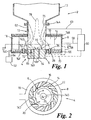
- Figure 1 is a diagrammatic and fragmentary longitudinal section of an embodiment of a gas turbine engine combustion system comprising liquid fuel injection nozzles formed according to the invention;
- Figure 2 is a representation of a section on line II-II in Figure 1 including certain further information;
- Figure 3 is a diagrammatic longitudinal sections of an embodiment of an fuel injection nozzle formed according to the invention which can be used in the combustion system in Figure 1.
- Figure 4 is a fragment of the section in Figure 3 shown enlarged with respect to Figure 3;
- Figure 5 is a fragment comparable to Figure 4 of a section of another embodiment of fuel injection nozzle formed according to the invention, and
- Figure 6 is a fragment comparable to Figure 4 of a section of a further embodiment of fuel injection nozzle formed according to the invention.
-
- In the drawings like references identify like or comparable parts.
- With reference to Figures 1 and 2 a gas turbine engine (not shown) comprises a plurality of combustors, such a combustor being indicated at 2. The
combustor 2 comprises aburner 4 having a burner head 6, an inflowingswirler assembly 8, a cylindrical pre-chamber 10, and a larger diametermain combustion chamber 12 downstream of the pre-chamber. - The
swirler assembly 8 comprises a plurality ofswirler vanes 14 disposed about a central axis and separatingpassages 16 along which compressed combustion air flows generally inwardly from anencircling manifold 18 supplied with compressed air by the compressor of the gas turbine engine. As shown particularly in Figure 2,passages 16 are oriented substantially tangentially to the periphery of the pre-chamber 10. On leaving thepassages 16 the combustion air enters the pre-chamber 10 adjacent to its upstream end with large tangential and smaller radial components of velocity. Aburner face 20 of the burner head 6 is disposed at the upstream end of the pre-chamber 10. - The
combustor 2 can burn fuel gas, for example, natural gas, or atomised liquid fuel. When operating with fuel gas, pilot fuel gas can be supplied to the pre-chamber 10 by a pilot gas system (not shown) whereas the main fuel gas supply is through gas jets or nozzles 22 (indicated only in Figure 2) opening into theswirler passages 16 adjacent to the radially outer ends of the passages. When operating in liquid fuel mode pilot liquid fuel is supplied from liquid fuel pilot jets ornozzles 26 at theburner face 20, and main liquid fuel is supplied in atomised droplets form from main liquid fuel injection jets ornozzles 26 opening into theswirler passages 16 adjacent to the radially inner or outlet ends of the swirler passages. - Each
injection nozzle 26 is connected to a suitable supply of liquid fuel via a liquid fuel manifold (not shown) associated with the combustion system. - With reference to Figures 3 and 4, each
injection nozzle 26 comprises anozzle body 28 provided with a circular section spin chamber 30 (known per se). Liquid fuel enters the spin chamber tangentially through an equi-angularly spaced array of bores orslots 32 and is thrown out thoughthroat 33 anddivergent passage 34 in a general direction A to anoutlet 36. Thepassage 34 widens progressively along direction A so that awall portion 38 of thepassage 34 is of substantially frusto-conical shape. Due to the vigorous rotational motion given to the fuel in the spin chamber, it tends to flow along the interior surface of thewall 38 and upon reaching theoutlet 36 of the nozzle, it is atomised into small droplets as it expands out of thepassage 34 into the airstream within the preswirler passages. This type of fuel nozzle is manufactured by Delavan Gas Turbine Products Division of BF Goodrich Aerospace, 811 4th Street, West Des Moines, Iowa 50265, U.S.A. - The present embodiment of the invention adds to this known type of fuel injection nozzle a
tubular electrode 40 of electrically conducting material which surrounds thenozzle body 28 and defines theoutlet 36 of thepassage 34. At theoutlet 36, theelectrode 40 has a substantially circular continuoussharp edge 42, which projects substantially along the direction of passage of the fuel through the nozzle. Apart from its uppermost end, theelectrode 40 is sandwiched betweentubular layers nozzle body 28 and which may be made of, for example, mica or a ceramic material. A radiallyinner surface 48 ofelectrode 40 is substantially cylindrical to match the shape of the outer surface of thenozzle body 28, while its radiallyouter surface 50 is substantially frusto-conical so as to define the included angle of thesharp edge 42. - In defining the
edge 42 of theelectrode 40 as sharp, the Applicant means sufficiently sharp to effectively impart charge to the fuel droplets as they rapidly leave theoutlet 46 of the nozzle. For example, the Applicant estimates that to fulfil this function, theedge 42 may have an included angle of about one half of a degree, and a radius of not more than about one micron, though the Applicant does not wish to be held to these values. It will be evident to the skilled person that to resist erosion from the fuel passing thereover and to maintain its sharpness over a long period, the electrode, or at least its exposed tip withsharp edge 42, should be made of a suitably hard, conductive and heat-resistant material, such as high speed tool steel or a hard facing material such as Stellite 6 (Trade Mark). - Advantageously, the electrostatic charge is imparted to the fuel by the electrode just at the point when the stream of fuel which adheres to the interior wall of the
nozzle passage 34 starts to break up into droplets as it leaves thenozzle outlet end 36. To provide this charge, a charge supply andcontrol unit 52, as known per se, (see Figure 1) is connected by line 54 to anannular conductor 56 supplying theelectrodes 40 of thenozzles 26. Preferably, the electrodes, and hence the fuel droplets exiting thenozzles 26, are positively charged. - Returning to Figures 1 and 2, the
swirler assembly 8, or at least wall portions of theswirler passages 16, for example surfaces of thevanes 14, comprise an electrode charged electrostatically vialine 58 by another charge supply andcontrol unit 60. When charged, theelectrode 8 is charged at the same polarity as the fuel droplets. - Pre-chamber 10 has a
chamber wall 62 which also comprises an electrode charged electrostatically vialine 63 by the supply andcontrol unit 60. When charged,electrode 62 is charged at the same polarity as the fuel droplets. - The burner head 6 comprises two
electrodes burner face 20.Electrode 64 is a central electrode represented as a cylinder in the drawings andelectrode 66 is a surrounding electrode represented as a ring. Theelectrode 66 is charged electrostatically at the same polarity as the fuel droplets. This may be achieved by connecting theelectrode 66 conductively to theelectrode 8 by aconductive connection 68 so that theelectrodes connection 68 and instead aline 70 may be provided so thatelectrode 66 may be charged by the supply andcontrol 36 via theline 70, in which case theelectrode 66 may be at a different potential to that of theelectrode 8. - Preferably
central electrode 64 is to be charged oppositely to the fuel, or at least to a lower potential. This may be achieved by connecting theelectrode 64 to a suitable electrostatic charge supply and control unit, or may be achieved, when the fuel charge is positive, by groundingcentral electrode 64 so as to be at a lower potential than the electrodes of thenozzles 26 and theother electrodes - An igniter for the fuel is represented at 72 embedded in the face of the
electrode 66 and may be adjacent to a periphery of thecentral electrode 64. - Insulation, for example mica or a ceramic, to maintain electrodes isolated from one another or other parts of the system is indicated at 74A, 74B, 74C, 74D, 74E, 74F and 74G.
- The fuel emitted by
nozzle 26 may be selectively electrostatically charged or not charged by theunits injector nozzles 26, the additional control of fuel atomisation, vaporisation, placement and combustion intensity obtainable by electrostatic charging of the electrodes is advantageous. Also as desired theelectrodes injector nozzles 26, good fuel atomisation, vaporisation, placement and combustion intensity may be achievable if none of the electrodes are charged. - The
control units control unit 60 may charge the respective electrodes, to which it is connected, to different respective extents or potentials. The source of static electricity may be a battery, or be derived from an auxiliary electrical generator driven by the gas turbine engine. - With particular reference to Figure 1, when the engine is performing under ignition operation mode with the liquid fuel from
nozzles 26 positively charged andcentral electrode 64 grounded, (i)electrodes connection 68, and (ii)electrode 62 may also be positively charged, for example slightly charged and thus be at a lesser potential with respect to theelectrodes dash lines 76 and a resulting fuel placement position or envelope demarcating the position of the fuel flow is indicated by interruptedlines 78. The charged droplets tend to be repelled from theswirler assembly 8 and from thewall 62 so the chance of that wall or those inassembly 8 becoming coked due to burning of fuel on their surfaces is reduced. Also, since the fuel is biased towards thecentral electrode 64, either by being attracted towards it, or at least by being less repelled by it than by the other electrodes, the chance of it being more effectively ignited by theigniter 72 as fuel moves thereover is improved. Fuel is not only electrostatically repelled by theswirler vanes 14 but also by theelectrode 66. By reason of the electrostatic conditions described at ignition operation, liquid fuel vaporisation rate is increased by (1) better fuel atomisation (Coulomb Fission), by (2) Coulomb force which is much greater than usual aerodynamic force so the fuel droplets can move against air flows, and by (3) Coulomb force preventing droplets coalescing. - When the engine is performing under load shed operation, the positive charge imparted to the fuel may preferably be a maximum the system can provide.
Central burner electrode 64 is grounded and (i)electrodes electrode 62 may also be positively charged, but to a higher potential than for ignition operation. Consequently, the electrostatic field is pinched withinpre-chamber 10, so again biasing the fuel/air mixture towards theelectrode 64.Electrodes electrodes electrode 64 pulls and pushes the fuel upstream towards the centre of the burner head 6 at the upstream end of the pre-chamber 10 resulting in improved fuel concentration and therefore improved flame stability. - Applicant's copending patent application of even date herewith and claiming priority from patent application no. GB0007970.7 gives further disclosure of such gas turbine engine combustion systems and the reader is referred thereto for further details not included in the present specification.
- The use of electrostatic control of fuel placement can assist in:-
- (a) Controlling NOx emissions.
- (b) Improving flame stability at ignition and load shed operation modes.
- (c) Reducing the need for to use more than one set of fuel nozzles to inject liquid fuel.
- (d) Reducing rumble in combustion systems, due to the reduction or elimination of unsteady combustion.
- (e) Enhancing fuel vaporisation rates and thereby reducing NOx.
- (f) Enabling liquid fuel staging to be used in "can" type combustion systems. Liquid fuel staging is the technique of using the same injector nozzle or set of nozzles to inject fuel at low flow rates for low load operation and also at higher flow rates for operation of the engine at higher loads. Hitherto, this has been very difficult to achieve because conventional injector nozzles must be designed to exhibit optimum atomisation over a restricted range of flow rates. The present invention tackles this problem by enabling better control of atomisation and placement of the fuel within the combustor.
- (g) Enabling use of a use of higher flow number liquid fuel injector nozzles while reducing the risk of coking of surfaces in the preswirler and the pre-chamber. Here, "flow number" is the UK flow number and is defined as the fuel flow rate through the nozzle in imperial gallons per hour divided by the square root of the pressure drop through the injector in pounds force per square inch. Conventionally, if high flow number nozzles are used, which give good fuel atomisation at high fuel flow rates, they cannot adequately atomise the fuel at low fuel flow rates, and this leads to larger fuel droplets which are more liable to impinge and burn on combustor surfaces, thereby leading to coking of the surfaces. However, the use as described above of charged electrodes both in the injector nozzles and in the combustor components reduces or eliminates this problem.
- (h) Enabling use of a wider range of liquid fuel types, due again to better atomisation and control of fuel placement.
- (i) Improving fuel and air mixing which results in reducing unburnt hydrocarbon emissions in the form of white smoke.
-
- In Figure 5 a fragment of a modified injection nozzle is shown at 26A in which an
uppermost face portion 48A of the radiallyinner face 48 of theelectrode 40 is of convex-bevel shape with respect to thepassage 34 and is more exposed to the passage than the upper end of theelectrode 40 of the nozzle 26 (Figures 3 and 4). This may give a longer wear life than the embodiment of Figure 4, since thesharp edge 36 has a larger included angle than that shown in Figure 4, though the edge radius need be no larger. However, the larger included angle of the edge may give a penalty in reduced effectiveness of imparting charge to the fuel. - In Figure 6 a fragment of another modified injection nozzle is shown at 26B in which the
upper end 36 of thepassage 34 is defined by an outer surface of a radially inturned lip 44B on theouter insulation tube 44. The lip 44B covers at least in part a substantially radially inwardly directed (with respect to the passage 34) inturned beak orlip 40B at the upper end of theelectrode 40, the lip bearing thesharp edge 42 which projects the electric charge in a direction substantially transverse to the direction A of fuel flow. In this case thesharp edge 42 is inset in thepassage 34 for protection from erosion at a position somewhat upstream of thedownstream passage end 36. This arrangement may give more efficient charge emission to the fuel stream immediately prior to its leaving the nozzle, especially in the case of fuels having high viscosity.
Claims (23)
- A liquid fuel injection nozzle for supplying atomised droplets of fuel to a combustion chamber in a gas turbine engine, said nozzle comprising a passage with an exit for the droplets to leave the nozzle, and electrode means disposed around the passage, the electrode means having sharp edge means positioned to impart electrostatic charge to the droplets as they leave the nozzle.
- A liquid fuel injection nozzle as claimed in claim 1, in which at least the sharp edge comprises an erosion resistant material.
- A liquid fuel injection nozzle as claimed in claim 1 or claim 2, in which the sharp edge comprises the exit of the nozzle.
- A liquid fuel injection nozzle as claimed in claim 1 or claim 2, in which the electrode means is adjacent the exit of the nozzle.
- A liquid fuel injection nozzle as claimed in any preceding claim, in which the sharp edge projects substantially along a general direction of flow of fuel along said passage.
- A liquid fuel injection nozzle as claimed in any one of claims 1 to 4, in which the sharp edge projects substantially across a general direction of flow of fuel along said passage.
- A liquid fuel injection nozzle as claimed in Claim 6, in which the sharp edge projects across an interior of the nozzle passage.
- A liquid fuel injection nozzle as claimed in any preceding claim, in which the electrode means forms at least part of a wall of nozzle passage.
- A liquid fuel injection nozzle as claimed in any preceding claim, in which the passage is divergent in the direction of the exit.
- A liquid fuel injection nozzle as claimed in any preceding claim, comprising a spin chamber adapted to swirl the fuel before entry to the passage.
- A liquid fuel injection nozzle as claimed in claim 10, in which the passage includes a throat portion which communicates with the spin chamber.
- A gas turbine engine combustion system comprising at least one liquid fuel injection nozzle as claimed in any preceding claim, and combustion system components comprising further electrode means connected to charging means arranged to electrostatically charge the further electrode means at predetermined polarities with respect to the nozzle electrode means, thereby to control distribution of fuel in the combustion chamber.
- A gas turbine engine combustion system comprising:a combustion main chamber,a combustion pre-chamber upstream thereof and opening into said main chamber, the pre-chamber being of smaller flow area than the main chamber and being disposed about a longitudinal axis,a burner face at an upstream end of said pre-chamber,a preswirler assembly comprising a plurality of preswirl passages communicating with the upstream end of the pre-chamber for supplying a preswirled air/fuel mixture to the pre-chamber, the preswirl passages being disposed about the longitudinal axis,a plurality of liquid fuel atomising injection nozzles as claimed in any one of Claims 1 to 11 and located in the preswirl passages to inject atomised liquid fuel thereinto,charging means operable to selectively electrostatically charge the nozzle electrode means at a pre-determined polarity thereby to impart electrostatic charge to the atomised fuel,preswirl electrode means forming at least portions of the preswirl passages, andcharging means operable to selectively electrostatically charge said preswirl electrode means at the same polarity as the nozzle electrode means, thereby to repel the atomised injected fuel from the preswirl passage portions.
- A gas turbine engine combustion system as claimed in claim 13, provided with first burner electrode means associated with said burner face, and means for holding the first burner electrode means at a potential with respect to the electrostatically charged fuel such that the fuel is biased towards the first burner electrode means.
- A gas turbine engine combustion system as claimed in claim 14, provided with second burner electrode means associated with said burner face, and means to selectively electrostatically charge the second burner electrode means at the same polarity as the charged fuel.
- A gas turbine engine combustion system as claimed in Claim 15, in which the second burner electrode means surrounds the first burner electrode means.
- A gas turbine engine combustion system as claimed in any one of Claims 13 to 16, in which fuel ignition means is embedded in the burner face.
- A gas turbine engine combustion system as claimed in claim 15 or claim 16, in which fuel ignition means is embedded in the second burner electrode means.
- A gas turbine engine combustion system as claimed in any one of claims 13 to 18, in which said pre-chamber is provided with pre-chamber electrode means comprising at least a portion of the pre-chamber, charging means being provided to selectively electrostatically charge the pre-chamber electrode means at the same polarity as the charge on the fuel.
- A gas turbine engine combustion system as claimed in Claim 19, in which a wall region of said pre-chamber comprises said pre-chamber electrode means.
- A gas turbine engine comprising a combustion system as claimed in any one of claims 12 to 20.
- A gas turbine engine as claimed in Claim 21, in which the charging means for the fuel is adapted to give the fuel an electrostatically positive charge.
- A gas turbine engine comprising a combustion system as claimed in any one of claims 14 to 18, or in claims 19 or 20 when appended to Claim 14, in which the first burner electrode means is provided with means to hold it at ground potential.
Applications Claiming Priority (4)
| Application Number | Priority Date | Filing Date | Title |
|---|---|---|---|
| GB0007970 | 2000-04-01 | ||
| GB0007971 | 2000-04-01 | ||
| GB0007970A GB2360836B (en) | 2000-04-01 | 2000-04-01 | Gas turbine engine combustion system |
| GB0007971A GB2360837B (en) | 2000-04-01 | 2000-04-01 | Liquid fuel injection nozzle |
Publications (3)
| Publication Number | Publication Date |
|---|---|
| EP1139021A2 true EP1139021A2 (en) | 2001-10-04 |
| EP1139021A3 EP1139021A3 (en) | 2002-08-07 |
| EP1139021B1 EP1139021B1 (en) | 2006-08-23 |
Family
ID=26244014
Family Applications (2)
| Application Number | Title | Priority Date | Filing Date |
|---|---|---|---|
| EP01303024A Expired - Lifetime EP1139021B1 (en) | 2000-04-01 | 2001-03-30 | Liquid fuel injection nozzles |
| EP01303021A Expired - Lifetime EP1139020B1 (en) | 2000-04-01 | 2001-03-30 | Gas turbine engine combustion system |
Family Applications After (1)
| Application Number | Title | Priority Date | Filing Date |
|---|---|---|---|
| EP01303021A Expired - Lifetime EP1139020B1 (en) | 2000-04-01 | 2001-03-30 | Gas turbine engine combustion system |
Country Status (3)
| Country | Link |
|---|---|
| US (2) | US6470684B2 (en) |
| EP (2) | EP1139021B1 (en) |
| DE (2) | DE60122414T2 (en) |
Cited By (5)
| Publication number | Priority date | Publication date | Assignee | Title |
|---|---|---|---|---|
| WO2007096294A1 (en) * | 2006-02-22 | 2007-08-30 | Siemens Aktiengesellschaft | A swirler for use in a burner of a gas turbine engine |
| EP1867842A1 (en) * | 2006-06-12 | 2007-12-19 | Siemens Aktiengesellschaft | A gas turbine engine and a method of operating a gas turbine engine |
| WO2008052830A1 (en) * | 2006-11-02 | 2008-05-08 | Siemens Aktiengesellschaft | Fuel-injector nozzle |
| JP2013506114A (en) * | 2009-09-29 | 2013-02-21 | サントル、ナショナール、ド、ラ、ルシェルシュ、シアンティフィク、(セーエヌエルエス) | Apparatus and method for electrostatic spraying of liquid, fuel injector including the apparatus, and use of the apparatus |
| CN113606606A (en) * | 2021-04-14 | 2021-11-05 | 中国航空发动机研究院 | Method for controlling engine by electric field and engine |
Families Citing this family (45)
| Publication number | Priority date | Publication date | Assignee | Title |
|---|---|---|---|---|
| US20030160105A1 (en) * | 2002-02-22 | 2003-08-28 | Kelly Arnold J. | Methods and apparatus for dispersing a conductive fluent material |
| EP1499800B1 (en) * | 2002-04-26 | 2011-06-29 | Rolls-Royce Corporation | Fuel premixing module for gas turbine engine combustor |
| US7065972B2 (en) * | 2004-05-21 | 2006-06-27 | Honeywell International, Inc. | Fuel-air mixing apparatus for reducing gas turbine combustor exhaust emissions |
| EP1821035A1 (en) | 2006-02-15 | 2007-08-22 | Siemens Aktiengesellschaft | Gas turbine burner and method of mixing fuel and air in a swirling area of a gas turbine burner |
| US7716931B2 (en) * | 2006-03-01 | 2010-05-18 | General Electric Company | Method and apparatus for assembling gas turbine engine |
| EP1867838A1 (en) * | 2006-06-12 | 2007-12-19 | Siemens Aktiengesellschaft | A method of substituting a material component of coatings of gas turbine components |
| US8851882B2 (en) * | 2009-04-03 | 2014-10-07 | Clearsign Combustion Corporation | System and apparatus for applying an electric field to a combustion volume |
| EP2246617B1 (en) * | 2009-04-29 | 2017-04-19 | Siemens Aktiengesellschaft | A burner for a gas turbine engine |
| US9080448B2 (en) | 2009-12-29 | 2015-07-14 | Rolls-Royce North American Technologies, Inc. | Gas turbine engine vanes |
| US11073280B2 (en) | 2010-04-01 | 2021-07-27 | Clearsign Technologies Corporation | Electrodynamic control in a burner system |
| GB201012626D0 (en) * | 2010-07-28 | 2010-09-08 | Rolls Royce Plc | Controllable flameholder |
| CN102426184B (en) * | 2011-11-14 | 2013-12-11 | 中国海洋石油总公司 | Conductivity sensor |
| EP2629008A1 (en) * | 2012-02-15 | 2013-08-21 | Siemens Aktiengesellschaft | Inclined fuel injection of fuel into a swirler slot |
| CN104169725B (en) | 2012-03-01 | 2018-04-17 | 克利尔赛恩燃烧公司 | It is configured to the inert electrode interacted electronic with flame and system |
| US9696031B2 (en) | 2012-03-27 | 2017-07-04 | Clearsign Combustion Corporation | System and method for combustion of multiple fuels |
| US9371994B2 (en) | 2013-03-08 | 2016-06-21 | Clearsign Combustion Corporation | Method for Electrically-driven classification of combustion particles |
| EP2856031B1 (en) | 2012-05-31 | 2016-10-19 | Clearsign Combustion Corporation | LOW NOx BURNER AND METHOD OF OPERATING A LOW NOx BURNER |
| WO2014040075A1 (en) | 2012-09-10 | 2014-03-13 | Clearsign Combustion Corporation | Electrodynamic combustion control with current limiting electrical element |
| US9151252B2 (en) | 2012-09-28 | 2015-10-06 | General Electric Company | Systems and methods for improved combustion |
| WO2014085720A1 (en) | 2012-11-27 | 2014-06-05 | Clearsign Combustion Corporation | Multijet burner with charge interaction |
| US9562681B2 (en) | 2012-12-11 | 2017-02-07 | Clearsign Combustion Corporation | Burner having a cast dielectric electrode holder |
| CN104838208A (en) | 2012-12-26 | 2015-08-12 | 克利尔赛恩燃烧公司 | Combustion system with grid switching electrode |
| US9441834B2 (en) | 2012-12-28 | 2016-09-13 | Clearsign Combustion Corporation | Wirelessly powered electrodynamic combustion control system |
| US9469819B2 (en) | 2013-01-16 | 2016-10-18 | Clearsign Combustion Corporation | Gasifier configured to electrodynamically agitate charged chemical species in a reaction region and related methods |
| US10364984B2 (en) | 2013-01-30 | 2019-07-30 | Clearsign Combustion Corporation | Burner system including at least one coanda surface and electrodynamic control system, and related methods |
| WO2014127306A1 (en) | 2013-02-14 | 2014-08-21 | Clearsign Combustion Corporation | SELECTABLE DILUTION LOW NOx BURNER |
| CA2892229A1 (en) | 2013-02-14 | 2014-08-21 | Clearsign Combustion Corporation | Startup method and mechanism for a burner having a perforated flame holder |
| US10571124B2 (en) | 2013-02-14 | 2020-02-25 | Clearsign Combustion Corporation | Selectable dilution low NOx burner |
| US9377189B2 (en) | 2013-02-21 | 2016-06-28 | Clearsign Combustion Corporation | Methods for operating an oscillating combustor with pulsed charger |
| US9696034B2 (en) | 2013-03-04 | 2017-07-04 | Clearsign Combustion Corporation | Combustion system including one or more flame anchoring electrodes and related methods |
| US9664386B2 (en) | 2013-03-05 | 2017-05-30 | Clearsign Combustion Corporation | Dynamic flame control |
| US10190767B2 (en) | 2013-03-27 | 2019-01-29 | Clearsign Combustion Corporation | Electrically controlled combustion fluid flow |
| WO2014183135A1 (en) | 2013-05-10 | 2014-11-13 | Clearsign Combustion Corporation | Combustion system and method for electrically assisted start-up |
| CN103263988A (en) * | 2013-06-03 | 2013-08-28 | 江苏大学 | Agricultural pneumatic type electrostatic atomization spray gun |
| WO2015017084A1 (en) | 2013-07-30 | 2015-02-05 | Clearsign Combustion Corporation | Combustor having a nonmetallic body with external electrodes |
| WO2015038245A1 (en) | 2013-09-13 | 2015-03-19 | Clearsign Combustion Corporation | Transient control of a combustion reaction |
| US20150104748A1 (en) | 2013-10-14 | 2015-04-16 | Clearsign Combustion Corporation | Electrodynamic combustion control (ecc) technology for biomass and coal systems |
| US10066835B2 (en) | 2013-11-08 | 2018-09-04 | Clearsign Combustion Corporation | Combustion system with flame location actuation |
| EP2942563A1 (en) * | 2014-05-09 | 2015-11-11 | Siemens Aktiengesellschaft | Swirler for a burner of a gas turbine engine, burner of a gas turbine engine and gas turbine engine |
| US20150345793A1 (en) * | 2014-06-03 | 2015-12-03 | Siemens Aktiengesellschaft | Fuel nozzle assembly with removable components |
| US10458647B2 (en) * | 2014-08-15 | 2019-10-29 | Clearsign Combustion Corporation | Adaptor for providing electrical combustion control to a burner |
| US10563626B2 (en) | 2018-06-27 | 2020-02-18 | United Technologies Corporation | Electrostatic flame control technology |
| CN113027615B (en) * | 2021-04-14 | 2022-11-04 | 中国航空发动机研究院 | Engine using axial electrode to control combustion |
| CN115539943B (en) * | 2022-09-22 | 2026-02-10 | 湛江电力有限公司 | A small charged spray burner |
| US12435669B1 (en) * | 2024-08-12 | 2025-10-07 | Rtx Corporation | Electrostatic flow guide dirt collector |
Citations (1)
| Publication number | Priority date | Publication date | Assignee | Title |
|---|---|---|---|---|
| US4439980A (en) | 1981-11-16 | 1984-04-03 | The United States Of America As Represented By The Secretary Of The Navy | Electrohydrodynamic (EHD) control of fuel injection in gas turbines |
Family Cites Families (19)
| Publication number | Priority date | Publication date | Assignee | Title |
|---|---|---|---|---|
| DE1121762B (en) * | 1960-04-14 | 1962-01-11 | Alberto Wobig | Burners for gaseous or liquid fuels |
| DE1401799A1 (en) | 1961-03-14 | 1968-10-10 | Kockums Mek Verkst S Aktiebola | Process for the fine distribution of fuel |
| US3358731A (en) * | 1966-04-01 | 1967-12-19 | Mobil Oil Corp | Liquid fuel surface combustion process and apparatus |
| US3746253A (en) * | 1970-09-21 | 1973-07-17 | Walberg & Co A | Coating system |
| US3749545A (en) | 1971-11-24 | 1973-07-31 | Univ Ohio State | Apparatus and method for controlling liquid fuel sprays for combustion |
| JPS6057907B2 (en) * | 1981-06-18 | 1985-12-17 | 工業技術院長 | Liquid mixing and atomization method |
| JPS618508A (en) | 1984-06-21 | 1986-01-16 | Agency Of Ind Science & Technol | Mixing and supplying method of fuel in combustion appratus |
| US4938019A (en) * | 1987-10-16 | 1990-07-03 | Fuel Systems Textron Inc. | Fuel nozzle and igniter assembly |
| US4892139A (en) * | 1988-07-11 | 1990-01-09 | H.P.S. Merrimack Corp. | Means and method for preventing unwanted accumulation in heat exchangers |
| DE4106563C2 (en) | 1991-03-01 | 1999-06-02 | Bosch Gmbh Robert | Device for the electrostatic atomization of liquids |
| US5515681A (en) | 1993-05-26 | 1996-05-14 | Simmonds Precision Engine Systems | Commonly housed electrostatic fuel atomizer and igniter apparatus for combustors |
| US5450724A (en) * | 1993-08-27 | 1995-09-19 | Northern Research & Engineering Corporation | Gas turbine apparatus including fuel and air mixer |
| DE19536604A1 (en) * | 1994-10-04 | 1996-04-11 | Simmonds Precision Engine Syst | Ignition device and ignition method using electrostatic nozzle and catalytic igniter |
| EP0728989B1 (en) | 1995-01-13 | 2001-11-28 | European Gas Turbines Limited | Gas turbine engine combustor |
| US5845480A (en) * | 1996-03-13 | 1998-12-08 | Unison Industries Limited Partnership | Ignition methods and apparatus using microwave and laser energy |
| GB2337102A (en) * | 1998-05-09 | 1999-11-10 | Europ Gas Turbines Ltd | Gas-turbine engine combustor |
| US6289676B1 (en) * | 1998-06-26 | 2001-09-18 | Pratt & Whitney Canada Corp. | Simplex and duplex injector having primary and secondary annular lud channels and primary and secondary lud nozzles |
| US6206307B1 (en) * | 1998-10-30 | 2001-03-27 | Charged Injection Corporation, By Said Arnold J. Kelly | Electrostatic atomizer with controller |
| US6474573B1 (en) * | 1998-12-31 | 2002-11-05 | Charge Injection Technologies, Inc. | Electrostatic atomizers |
-
2001
- 2001-03-30 DE DE60122414T patent/DE60122414T2/en not_active Expired - Fee Related
- 2001-03-30 EP EP01303024A patent/EP1139021B1/en not_active Expired - Lifetime
- 2001-03-30 US US09/823,279 patent/US6470684B2/en not_active Expired - Fee Related
- 2001-03-30 EP EP01303021A patent/EP1139020B1/en not_active Expired - Lifetime
- 2001-03-30 DE DE60122415T patent/DE60122415T2/en not_active Expired - Fee Related
- 2001-03-30 US US09/823,930 patent/US6695234B2/en not_active Expired - Fee Related
Patent Citations (1)
| Publication number | Priority date | Publication date | Assignee | Title |
|---|---|---|---|---|
| US4439980A (en) | 1981-11-16 | 1984-04-03 | The United States Of America As Represented By The Secretary Of The Navy | Electrohydrodynamic (EHD) control of fuel injection in gas turbines |
Cited By (10)
| Publication number | Priority date | Publication date | Assignee | Title |
|---|---|---|---|---|
| WO2007096294A1 (en) * | 2006-02-22 | 2007-08-30 | Siemens Aktiengesellschaft | A swirler for use in a burner of a gas turbine engine |
| US8302404B2 (en) | 2006-02-22 | 2012-11-06 | Siemens Aktiengesellschaft | Swirler for use in a burner of a gas turbine engine |
| EP1867842A1 (en) * | 2006-06-12 | 2007-12-19 | Siemens Aktiengesellschaft | A gas turbine engine and a method of operating a gas turbine engine |
| WO2007144207A1 (en) * | 2006-06-12 | 2007-12-21 | Siemens Aktiengesellschaft | A gas turbine engine and a method of operating a gas turbine engine |
| WO2008052830A1 (en) * | 2006-11-02 | 2008-05-08 | Siemens Aktiengesellschaft | Fuel-injector nozzle |
| CN101535715B (en) * | 2006-11-02 | 2011-05-11 | 西门子公司 | fuel injector nozzle |
| RU2419030C2 (en) * | 2006-11-02 | 2011-05-20 | Сименс Акциенгезелльшафт | Fuel nozzle |
| US8662423B2 (en) | 2006-11-02 | 2014-03-04 | Siemens Aktiengesellschaft | Fuel-injector nozzle |
| JP2013506114A (en) * | 2009-09-29 | 2013-02-21 | サントル、ナショナール、ド、ラ、ルシェルシュ、シアンティフィク、(セーエヌエルエス) | Apparatus and method for electrostatic spraying of liquid, fuel injector including the apparatus, and use of the apparatus |
| CN113606606A (en) * | 2021-04-14 | 2021-11-05 | 中国航空发动机研究院 | Method for controlling engine by electric field and engine |
Also Published As
| Publication number | Publication date |
|---|---|
| DE60122415T2 (en) | 2006-12-21 |
| US20010045474A1 (en) | 2001-11-29 |
| EP1139021A3 (en) | 2002-08-07 |
| US6695234B2 (en) | 2004-02-24 |
| US20010045094A1 (en) | 2001-11-29 |
| DE60122415D1 (en) | 2006-10-05 |
| DE60122414D1 (en) | 2006-10-05 |
| DE60122414T2 (en) | 2006-12-21 |
| EP1139021B1 (en) | 2006-08-23 |
| US6470684B2 (en) | 2002-10-29 |
| EP1139020A1 (en) | 2001-10-04 |
| EP1139020B1 (en) | 2006-08-23 |
Similar Documents
| Publication | Publication Date | Title |
|---|---|---|
| EP1139021B1 (en) | Liquid fuel injection nozzles | |
| US8146837B2 (en) | Radially outward flowing air-blast fuel injection for gas turbine engine | |
| US6453660B1 (en) | Combustor mixer having plasma generating nozzle | |
| US8662423B2 (en) | Fuel-injector nozzle | |
| CN106461219B (en) | Burner arrangement for a combustion device | |
| US3834159A (en) | Combustion apparatus | |
| GB2219627A (en) | Nozzles for in-cylinder fuel injection | |
| EP4113009B1 (en) | Torch ignitor for a gas turbine engine | |
| US8763401B2 (en) | Integrated fuel nozzle and ignition assembly for gas turbine engines | |
| AU2004201436B2 (en) | Augmentor pilot nozzle | |
| GB2360836A (en) | Gas turbine engine combustion system | |
| US20020063176A1 (en) | Device and method for the electrostatic atomization of a liquid medium | |
| GB2360837A (en) | Liquid fuel injection nozzle | |
| US20080184707A1 (en) | Fuel manifold for combustion systems | |
| GB1578418A (en) | Fuel injectors | |
| US20100038455A1 (en) | Liquid ejector | |
| JPS6298111A (en) | Burner device | |
| JPS5945896B2 (en) | Pulverized coal burner ignition system |
Legal Events
| Date | Code | Title | Description |
|---|---|---|---|
| PUAI | Public reference made under article 153(3) epc to a published international application that has entered the european phase |
Free format text: ORIGINAL CODE: 0009012 |
|
| AK | Designated contracting states |
Kind code of ref document: A2 Designated state(s): AT BE CH CY DE DK ES FI FR GB GR IE IT LI LU MC NL PT SE TR |
|
| AX | Request for extension of the european patent |
Free format text: AL;LT;LV;MK;RO;SI |
|
| PUAL | Search report despatched |
Free format text: ORIGINAL CODE: 0009013 |
|
| AK | Designated contracting states |
Kind code of ref document: A3 Designated state(s): AT BE CH CY DE DK ES FI FR GB GR IE IT LI LU MC NL PT SE TR |
|
| AX | Request for extension of the european patent |
Free format text: AL;LT;LV;MK;RO;SI |
|
| 17P | Request for examination filed |
Effective date: 20020624 |
|
| 17Q | First examination report despatched |
Effective date: 20021024 |
|
| AKX | Designation fees paid |
Designated state(s): CH DE FR GB IT LI |
|
| GRAP | Despatch of communication of intention to grant a patent |
Free format text: ORIGINAL CODE: EPIDOSNIGR1 |
|
| RIC1 | Information provided on ipc code assigned before grant |
Ipc: F23C 99/00 20060101AFI20060220BHEP Ipc: F23R 3/28 20060101ALI20060220BHEP |
|
| RAP1 | Party data changed (applicant data changed or rights of an application transferred) |
Owner name: ALSTOM TECHNOLOGY LTD |
|
| GRAS | Grant fee paid |
Free format text: ORIGINAL CODE: EPIDOSNIGR3 |
|
| GRAA | (expected) grant |
Free format text: ORIGINAL CODE: 0009210 |
|
| RBV | Designated contracting states (corrected) |
Designated state(s): CH DE FR IT LI |
|
| AK | Designated contracting states |
Kind code of ref document: B1 Designated state(s): CH DE FR IT LI |
|
| PG25 | Lapsed in a contracting state [announced via postgrant information from national office to epo] |
Ref country code: IT Free format text: LAPSE BECAUSE OF FAILURE TO SUBMIT A TRANSLATION OF THE DESCRIPTION OR TO PAY THE FEE WITHIN THE PRESCRIBED TIME-LIMIT;WARNING: LAPSES OF ITALIAN PATENTS WITH EFFECTIVE DATE BEFORE 2007 MAY HAVE OCCURRED AT ANY TIME BEFORE 2007. THE CORRECT EFFECTIVE DATE MAY BE DIFFERENT FROM THE ONE RECORDED. Effective date: 20060823 Ref country code: LI Free format text: LAPSE BECAUSE OF FAILURE TO SUBMIT A TRANSLATION OF THE DESCRIPTION OR TO PAY THE FEE WITHIN THE PRESCRIBED TIME-LIMIT Effective date: 20060823 Ref country code: CH Free format text: LAPSE BECAUSE OF FAILURE TO SUBMIT A TRANSLATION OF THE DESCRIPTION OR TO PAY THE FEE WITHIN THE PRESCRIBED TIME-LIMIT Effective date: 20060823 |
|
| REG | Reference to a national code |
Ref country code: CH Ref legal event code: EP |
|
| REF | Corresponds to: |
Ref document number: 60122415 Country of ref document: DE Date of ref document: 20061005 Kind code of ref document: P |
|
| ET | Fr: translation filed | ||
| REG | Reference to a national code |
Ref country code: CH Ref legal event code: PL |
|
| PLBE | No opposition filed within time limit |
Free format text: ORIGINAL CODE: 0009261 |
|
| STAA | Information on the status of an ep patent application or granted ep patent |
Free format text: STATUS: NO OPPOSITION FILED WITHIN TIME LIMIT |
|
| 26N | No opposition filed |
Effective date: 20070524 |
|
| PGFP | Annual fee paid to national office [announced via postgrant information from national office to epo] |
Ref country code: DE Payment date: 20090320 Year of fee payment: 9 Ref country code: IT Payment date: 20090325 Year of fee payment: 9 |
|
| PGFP | Annual fee paid to national office [announced via postgrant information from national office to epo] |
Ref country code: FR Payment date: 20090312 Year of fee payment: 9 |
|
| REG | Reference to a national code |
Ref country code: FR Ref legal event code: ST Effective date: 20101130 |
|
| PG25 | Lapsed in a contracting state [announced via postgrant information from national office to epo] |
Ref country code: FR Free format text: LAPSE BECAUSE OF NON-PAYMENT OF DUE FEES Effective date: 20100331 |
|
| PG25 | Lapsed in a contracting state [announced via postgrant information from national office to epo] |
Ref country code: DE Free format text: LAPSE BECAUSE OF NON-PAYMENT OF DUE FEES Effective date: 20101001 |
|
| PG25 | Lapsed in a contracting state [announced via postgrant information from national office to epo] |
Ref country code: IT Free format text: LAPSE BECAUSE OF NON-PAYMENT OF DUE FEES Effective date: 20100330 |