EP1138986A1 - Apparatus and method for controlling an automatic transmission - Google Patents
Apparatus and method for controlling an automatic transmission Download PDFInfo
- Publication number
- EP1138986A1 EP1138986A1 EP01106438A EP01106438A EP1138986A1 EP 1138986 A1 EP1138986 A1 EP 1138986A1 EP 01106438 A EP01106438 A EP 01106438A EP 01106438 A EP01106438 A EP 01106438A EP 1138986 A1 EP1138986 A1 EP 1138986A1
- Authority
- EP
- European Patent Office
- Prior art keywords
- torque
- output shaft
- gear change
- shaft torque
- gear
- Prior art date
- Legal status (The legal status is an assumption and is not a legal conclusion. Google has not performed a legal analysis and makes no representation as to the accuracy of the status listed.)
- Withdrawn
Links
- 230000005540 biological transmission Effects 0.000 title claims abstract description 116
- 238000000034 method Methods 0.000 title claims description 5
- 230000003247 decreasing effect Effects 0.000 claims abstract description 10
- 210000000078 claw Anatomy 0.000 claims description 8
- 230000001133 acceleration Effects 0.000 claims description 3
- 238000012545 processing Methods 0.000 description 20
- 238000010586 diagram Methods 0.000 description 5
- 230000035939 shock Effects 0.000 description 3
- 238000013475 authorization Methods 0.000 description 2
- 238000007664 blowing Methods 0.000 description 1
- 238000004891 communication Methods 0.000 description 1
- 238000012937 correction Methods 0.000 description 1
- 230000006866 deterioration Effects 0.000 description 1
- 239000003112 inhibitor Substances 0.000 description 1
Images






Classifications
-
- B—PERFORMING OPERATIONS; TRANSPORTING
- B60—VEHICLES IN GENERAL
- B60W—CONJOINT CONTROL OF VEHICLE SUB-UNITS OF DIFFERENT TYPE OR DIFFERENT FUNCTION; CONTROL SYSTEMS SPECIALLY ADAPTED FOR HYBRID VEHICLES; ROAD VEHICLE DRIVE CONTROL SYSTEMS FOR PURPOSES NOT RELATED TO THE CONTROL OF A PARTICULAR SUB-UNIT
- B60W10/00—Conjoint control of vehicle sub-units of different type or different function
- B60W10/04—Conjoint control of vehicle sub-units of different type or different function including control of propulsion units
- B60W10/06—Conjoint control of vehicle sub-units of different type or different function including control of propulsion units including control of combustion engines
-
- B—PERFORMING OPERATIONS; TRANSPORTING
- B60—VEHICLES IN GENERAL
- B60W—CONJOINT CONTROL OF VEHICLE SUB-UNITS OF DIFFERENT TYPE OR DIFFERENT FUNCTION; CONTROL SYSTEMS SPECIALLY ADAPTED FOR HYBRID VEHICLES; ROAD VEHICLE DRIVE CONTROL SYSTEMS FOR PURPOSES NOT RELATED TO THE CONTROL OF A PARTICULAR SUB-UNIT
- B60W10/00—Conjoint control of vehicle sub-units of different type or different function
- B60W10/04—Conjoint control of vehicle sub-units of different type or different function including control of propulsion units
-
- B—PERFORMING OPERATIONS; TRANSPORTING
- B60—VEHICLES IN GENERAL
- B60W—CONJOINT CONTROL OF VEHICLE SUB-UNITS OF DIFFERENT TYPE OR DIFFERENT FUNCTION; CONTROL SYSTEMS SPECIALLY ADAPTED FOR HYBRID VEHICLES; ROAD VEHICLE DRIVE CONTROL SYSTEMS FOR PURPOSES NOT RELATED TO THE CONTROL OF A PARTICULAR SUB-UNIT
- B60W10/00—Conjoint control of vehicle sub-units of different type or different function
- B60W10/10—Conjoint control of vehicle sub-units of different type or different function including control of change-speed gearings
- B60W10/11—Stepped gearings
-
- B—PERFORMING OPERATIONS; TRANSPORTING
- B60—VEHICLES IN GENERAL
- B60W—CONJOINT CONTROL OF VEHICLE SUB-UNITS OF DIFFERENT TYPE OR DIFFERENT FUNCTION; CONTROL SYSTEMS SPECIALLY ADAPTED FOR HYBRID VEHICLES; ROAD VEHICLE DRIVE CONTROL SYSTEMS FOR PURPOSES NOT RELATED TO THE CONTROL OF A PARTICULAR SUB-UNIT
- B60W30/00—Purposes of road vehicle drive control systems not related to the control of a particular sub-unit, e.g. of systems using conjoint control of vehicle sub-units
- B60W30/18—Propelling the vehicle
-
- B—PERFORMING OPERATIONS; TRANSPORTING
- B60—VEHICLES IN GENERAL
- B60W—CONJOINT CONTROL OF VEHICLE SUB-UNITS OF DIFFERENT TYPE OR DIFFERENT FUNCTION; CONTROL SYSTEMS SPECIALLY ADAPTED FOR HYBRID VEHICLES; ROAD VEHICLE DRIVE CONTROL SYSTEMS FOR PURPOSES NOT RELATED TO THE CONTROL OF A PARTICULAR SUB-UNIT
- B60W30/00—Purposes of road vehicle drive control systems not related to the control of a particular sub-unit, e.g. of systems using conjoint control of vehicle sub-units
- B60W30/18—Propelling the vehicle
- B60W30/1819—Propulsion control with control means using analogue circuits, relays or mechanical links
-
- B—PERFORMING OPERATIONS; TRANSPORTING
- B60—VEHICLES IN GENERAL
- B60W—CONJOINT CONTROL OF VEHICLE SUB-UNITS OF DIFFERENT TYPE OR DIFFERENT FUNCTION; CONTROL SYSTEMS SPECIALLY ADAPTED FOR HYBRID VEHICLES; ROAD VEHICLE DRIVE CONTROL SYSTEMS FOR PURPOSES NOT RELATED TO THE CONTROL OF A PARTICULAR SUB-UNIT
- B60W30/00—Purposes of road vehicle drive control systems not related to the control of a particular sub-unit, e.g. of systems using conjoint control of vehicle sub-units
- B60W30/18—Propelling the vehicle
- B60W30/19—Improvement of gear change, e.g. by synchronisation or smoothing gear shift
-
- F—MECHANICAL ENGINEERING; LIGHTING; HEATING; WEAPONS; BLASTING
- F16—ENGINEERING ELEMENTS AND UNITS; GENERAL MEASURES FOR PRODUCING AND MAINTAINING EFFECTIVE FUNCTIONING OF MACHINES OR INSTALLATIONS; THERMAL INSULATION IN GENERAL
- F16H—GEARING
- F16H3/00—Toothed gearings for conveying rotary motion with variable gear ratio or for reversing rotary motion
- F16H3/02—Toothed gearings for conveying rotary motion with variable gear ratio or for reversing rotary motion without gears having orbital motion
- F16H3/08—Toothed gearings for conveying rotary motion with variable gear ratio or for reversing rotary motion without gears having orbital motion exclusively or essentially with continuously meshing gears, that can be disengaged from their shafts
- F16H3/12—Toothed gearings for conveying rotary motion with variable gear ratio or for reversing rotary motion without gears having orbital motion exclusively or essentially with continuously meshing gears, that can be disengaged from their shafts with means for synchronisation not incorporated in the clutches
-
- B—PERFORMING OPERATIONS; TRANSPORTING
- B60—VEHICLES IN GENERAL
- B60W—CONJOINT CONTROL OF VEHICLE SUB-UNITS OF DIFFERENT TYPE OR DIFFERENT FUNCTION; CONTROL SYSTEMS SPECIALLY ADAPTED FOR HYBRID VEHICLES; ROAD VEHICLE DRIVE CONTROL SYSTEMS FOR PURPOSES NOT RELATED TO THE CONTROL OF A PARTICULAR SUB-UNIT
- B60W2510/00—Input parameters relating to a particular sub-units
- B60W2510/10—Change speed gearings
- B60W2510/105—Output torque
-
- B—PERFORMING OPERATIONS; TRANSPORTING
- B60—VEHICLES IN GENERAL
- B60W—CONJOINT CONTROL OF VEHICLE SUB-UNITS OF DIFFERENT TYPE OR DIFFERENT FUNCTION; CONTROL SYSTEMS SPECIALLY ADAPTED FOR HYBRID VEHICLES; ROAD VEHICLE DRIVE CONTROL SYSTEMS FOR PURPOSES NOT RELATED TO THE CONTROL OF A PARTICULAR SUB-UNIT
- B60W2710/00—Output or target parameters relating to a particular sub-units
- B60W2710/06—Combustion engines, Gas turbines
- B60W2710/0666—Engine torque
-
- B—PERFORMING OPERATIONS; TRANSPORTING
- B60—VEHICLES IN GENERAL
- B60W—CONJOINT CONTROL OF VEHICLE SUB-UNITS OF DIFFERENT TYPE OR DIFFERENT FUNCTION; CONTROL SYSTEMS SPECIALLY ADAPTED FOR HYBRID VEHICLES; ROAD VEHICLE DRIVE CONTROL SYSTEMS FOR PURPOSES NOT RELATED TO THE CONTROL OF A PARTICULAR SUB-UNIT
- B60W2710/00—Output or target parameters relating to a particular sub-units
- B60W2710/10—Change speed gearings
- B60W2710/105—Output torque
-
- F—MECHANICAL ENGINEERING; LIGHTING; HEATING; WEAPONS; BLASTING
- F16—ENGINEERING ELEMENTS AND UNITS; GENERAL MEASURES FOR PRODUCING AND MAINTAINING EFFECTIVE FUNCTIONING OF MACHINES OR INSTALLATIONS; THERMAL INSULATION IN GENERAL
- F16H—GEARING
- F16H61/00—Control functions within control units of change-speed- or reversing-gearings for conveying rotary motion ; Control of exclusively fluid gearing, friction gearing, gearings with endless flexible members or other particular types of gearing
- F16H61/04—Smoothing ratio shift
- F16H2061/0425—Bridging torque interruption
-
- F—MECHANICAL ENGINEERING; LIGHTING; HEATING; WEAPONS; BLASTING
- F16—ENGINEERING ELEMENTS AND UNITS; GENERAL MEASURES FOR PRODUCING AND MAINTAINING EFFECTIVE FUNCTIONING OF MACHINES OR INSTALLATIONS; THERMAL INSULATION IN GENERAL
- F16H—GEARING
- F16H61/00—Control functions within control units of change-speed- or reversing-gearings for conveying rotary motion ; Control of exclusively fluid gearing, friction gearing, gearings with endless flexible members or other particular types of gearing
- F16H61/04—Smoothing ratio shift
- F16H61/0437—Smoothing ratio shift by using electrical signals
-
- F—MECHANICAL ENGINEERING; LIGHTING; HEATING; WEAPONS; BLASTING
- F16—ENGINEERING ELEMENTS AND UNITS; GENERAL MEASURES FOR PRODUCING AND MAINTAINING EFFECTIVE FUNCTIONING OF MACHINES OR INSTALLATIONS; THERMAL INSULATION IN GENERAL
- F16H—GEARING
- F16H61/00—Control functions within control units of change-speed- or reversing-gearings for conveying rotary motion ; Control of exclusively fluid gearing, friction gearing, gearings with endless flexible members or other particular types of gearing
- F16H61/68—Control functions within control units of change-speed- or reversing-gearings for conveying rotary motion ; Control of exclusively fluid gearing, friction gearing, gearings with endless flexible members or other particular types of gearing specially adapted for stepped gearings
- F16H61/682—Control functions within control units of change-speed- or reversing-gearings for conveying rotary motion ; Control of exclusively fluid gearing, friction gearing, gearings with endless flexible members or other particular types of gearing specially adapted for stepped gearings with interruption of drive
-
- F—MECHANICAL ENGINEERING; LIGHTING; HEATING; WEAPONS; BLASTING
- F16—ENGINEERING ELEMENTS AND UNITS; GENERAL MEASURES FOR PRODUCING AND MAINTAINING EFFECTIVE FUNCTIONING OF MACHINES OR INSTALLATIONS; THERMAL INSULATION IN GENERAL
- F16H—GEARING
- F16H63/00—Control outputs from the control unit to change-speed- or reversing-gearings for conveying rotary motion or to other devices than the final output mechanism
- F16H63/40—Control outputs from the control unit to change-speed- or reversing-gearings for conveying rotary motion or to other devices than the final output mechanism comprising signals other than signals for actuating the final output mechanisms
- F16H63/50—Signals to an engine or motor
- F16H63/502—Signals to an engine or motor for smoothing gear shifts
-
- Y—GENERAL TAGGING OF NEW TECHNOLOGICAL DEVELOPMENTS; GENERAL TAGGING OF CROSS-SECTIONAL TECHNOLOGIES SPANNING OVER SEVERAL SECTIONS OF THE IPC; TECHNICAL SUBJECTS COVERED BY FORMER USPC CROSS-REFERENCE ART COLLECTIONS [XRACs] AND DIGESTS
- Y10—TECHNICAL SUBJECTS COVERED BY FORMER USPC
- Y10T—TECHNICAL SUBJECTS COVERED BY FORMER US CLASSIFICATION
- Y10T74/00—Machine element or mechanism
- Y10T74/19—Gearing
Definitions
- the present invention relates to a control apparatus of an automatic transmission having a gear mechanism and a method of controlling the same.
- a conventional example of an automatic transmission having a gear transmission mechanism is disclosed in Japanese Patent Unexamined Publication No. 61-45163.
- the fastest gear of the gear transmission is locked or released by using a friction clutch, and the engine revolutions are controlled by sliding the friction clutch to change the speed at the gear change operation in synchronization with the revolutions of an output shaft, thus enabling a smooth gear change.
- This automatic transmission has a problem that, if the friction clutch has only a small torque capacity, a gear change in a high output shaft torque condition causes a driver and the like to feel odd due to a difference from a torque that can be generated by the friction clutch transmitted as a torque change to the output shaft.
- an automatic transmission having torque transmission means between an input shaft and an output shaft of a gear transmission, the torque transmission means on at least one gear change stage serving as a friction clutch, and the torque transmission means on other gear change stages serving as claw clutches, for changing speed smoothly by controlling the friction clutch at a gear change from one gear change stage to another, wherein, if output shaft torque exceeds limit transmission output shaft torque obtained by a torque capacity of the friction clutch multiplied by a gear ratio provided for the friction clutch when a gear change command is issued in the automatic transmission, engine torque is controlled so that the output shaft torque becomes equal to the limit transmission output shaft torque and then an engine torque control is switched when the output shaft torque reaches the same value as the limit transmission output shaft torque to start to change the speed.
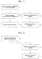
- a gear change command is outputted from a gear change command output means 1
- a torque comparison means 4 performs to compare the current output shaft torque with limit transmission output shaft torque. If the output shaft torque is larger than the limit transmission output shaft torque, a gear change authorization means 2 does not issue the gear change command to a gear change means 3.
- a torque control means 5 controls the output shaft torque so as to approximate to the limit transmission output shaft torque. This can achieve that, when the output shaft torque drops to the limit transmission output shaft torque or smaller, the gear change authorization means 2 issues a gear change command to the gear change means to start a gear change. This causes the output shaft torque to shift smoothly, thereby enabling a smooth gear change even if the speed is changed in a high output shaft torque condition.
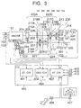
- Fig. 2 there is shown a block diagram, in completing the gear change, of the embodiment of the present invention.
- the torque comparison means 4 compares the current output shaft torque with target output shaft torque. Unless the output shaft torque is equal to the target output shaft torque, the torque control means 5 controls the output shaft torque so as to approximate to the target output shaft torque. This causes the output shaft torque to shift smoothly, thus enabling a smooth gear change even if the output shaft torque at the completion of the gear change differs from the target output shaft torque.
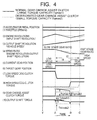
- FIG. 3 there is shown an example of an entire detailed configuration of an automobile using a control apparatus of the automobile according to the present invention.
- an engine is used as a power generator and a gear transmission is used as power transmitting means.
- a control unit 405 includes an electronic control throttle control unit 401 for controlling an electronic control throttle 103, an engine control unit 402 for controlling the engine, and a transmission control unit 403 for controlling the transmission.
- the engine 101 includes the electronic control throttle 103 for adjusting engine torque and an engine revolutions sensor 102 for detecting engine revolutions.
- the engine 101 is controlled by an engine control unit 402.
- the electronic control throttle 103 is controlled by an electronic control throttle control unit 401.
- the gear transmission is constructed to include a starting clutch 202, a starting clutch actuator 203, a wire 204, an input shaft 205, an output shaft 301, gears 206, 207, 208, 209, 210, 211, 212, 213, 214, 215, 230, and 231, a 1- to 2-speed dog clutch 220A, a 3- to 4-speed dog clutch 220C, a 6-speed dog clutch 220E, a shift actuator 221, a select actuator 222, shifter forks 223, 224, and 232, a gear change assist clutch 225, a gear change assist clutch actuator 226, and an output shaft revolutions sensor 300.
- the 1- to 2-speed dog clutch 220A comprises a clutch hub 216A, a sleeve 217A, synchronizer rings 218A and 218B, and gear splines 219A and 219B.
- the 3- to 4-speed dog clutch 220C includes a clutch hub 216C, a sleeve 217C, synchronizer rings 218C and 218D, and gear splines 219C and 219D.
- the 6-speed dog clutch 220E includes a clutch hub 216E, a sleeve 217E, a synchronizer ring 218E, and a gear spline 219E. A reverse mechanism is omitted in this diagram.
- Actuators 203, 221, 222, and 226 composing the gear transmission are controlled by the transmission control unit 403 with an oil pressure or a motor.
- Engine torque outputted from the engine 101 is transmitted to the input shaft 205 of the gear transmission via the flywheel 201 and the starting clutch 202, transmitted to the output shaft 301 via any one of the gears 206, 207, 208, 209, 210, 211, 212, 213, 214, 215, 230, and 231, and finally transmitted to tires to run the automobile.
- the starting clutch 202 for transmitting the engine torque to the input shaft 205 of the gear transmission is locked or released by the starting clutch actuator 203 to control transmissibility of the engine torque.
- Traveling of one of the 1- to 4-speed and 6-speed is determined by moving any one of the gears 210, 212, and 230 rotatable to the input shaft 205 or one of the gears 207 and 209 rotatable to the output shaft 301 with moving sleeves 217A, 217C, 217E of the claw clutches 220A, 220C, and 220E (for example, dog clutches) by means of the shifter forks 223, 224, and 232 to cause one of the clutch hubs 216A, 216C, and 216E to be fastened to one of the gear splines 219A, 219B, 219C, 219D, and 219E.
- moving sleeves 217A, 217C, 217E of the claw clutches 220A, 220C, and 220E for example, dog clutches
- the shifter forks 223, 224, and 232 are driven by the shift actuator 221 and the select actuator 222. At this time in order to synchronize the clutch hubs 216A, 216C, and 216E with the gear splines 219A, 219B, 219C, 219D, and 219E, there are provided the synchronizer rings 218A, 218B, 218C, 218D, and 218E.
- a drive shaft torque of the input shaft 205 is transmitted to the output shaft 301 via the gear 206, the gear 207, and the clutch hub 216A.
- the gear 207 is coupled to the clutch hub 216A through the sleeve 217A.
- the drive torque of the input shaft 205 is transmitted to the output shaft 301 via the gear 208, the gear 209, and the clutch hub 216A.
- the gear 209 is coupled to the clutch hub 216A through the sleeve 217A.
- the drive torque of the input shaft 205 is transmitted to the output shaft 301 via the clutch hub 216C, the gear 210, and the gear 211.
- the gear 210 is coupled to the clutch hub 216C through the sleeve 217C.
- the drive torque of the input shaft 205 is transmitted to the output shaft 301 via the clutch hub 216C, the gear 212, and the gear 214.
- the gear 212 is coupled to the clutch hub 216C through the sleeve 217C.
- the drive torque of the input shaft 205 is transmitted to the output shaft 301 via the clutch hub 216E, the gear 230, and the gear 231.
- the gear 230 is coupled to the clutch hub 216E through the sleeve 217E.
- the dog clutches 220A, 220C, and 220E are provided for each of the 1- to 4-speed and the 6-speed gears. During traveling, only one gear should be necessarily fastened by the dog clutches 220A, 220C, and 220E and other gears should be released.
- the input shaft 205 is fastened to the gear 214 with the gear change assist clutch 225 before traveling.
- the gear change assist clutch 225 is driven by the gear change assist clutch actuator 226.
- the gear change assist clutch 225 is controlled to control the transmission torque, thereby preventing a sense of weakness or an occurrence of blowoff.
- the transmission control unit 403 receives inputs of automobile sensor signals from an accelerator pedal sensor 406 for detecting an accelerator depression amount, an inhibitor switch 407 for detecting a shift lever position, the output shaft revolutions sensor 300 for detecting the revolutions of the output shaft, a mode switch 408 for changing between an automatic transmission mode and a manual transmission, a plus switch 409 for incrementing the gear change stage by one in the manual transmission mode, and a minus switch 410 for decrementing the gear change stage by one in the manual transmission mode.
- the transmission control unit 403 is coupled to the engine control unit 402 and to the electronic control throttle control unit 401 via a communication line 404 such as control area network (CAN).
- CAN control area network
- the transmission control unit 403 keeps up on an operational condition on the basis of received signals and controls a starting clutch condition and a gear position to the appropriate ones.
- the starting clutch 202 controls fastening during fixed-speed traveling or gear change.
- the transmission control unit 403 controls the electronic control throttle 103 via the electronic control throttle control unit 401 so as to prevent the engine 101 from blowing out during gear change in the automatic transmission mode.
- the transmission control unit 403 controls the electronic control throttle 103 and the gear change assist clutch 225 for a smooth change from transmission torque immediately before the gear change to transmission torque immediately after the gear change. Furthermore, it sends a correction value for an ignition timing from the transmission control unit 403 to the engine control unit 402 to control the ignition timing.
- the electronic control throttle 103 is controlled to absorb the shock caused by a rapid gear change before and after the gear change so as to reduce a sense of discomfort for a driver.
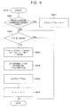
- a timing chart of a gear change operation for the gear change assist clutch 225 with large and small torque capacities Assuming that a low speed corresponds to 1-speed and a high speed to 2-speed, a solid line indicates operations of respective components of a gear change assist clutch having a large torque capacity and a phantom line indicates operations of respective components of a gear change assist clutch having a small torque capacity in the sample gear change of an upshift from the 1-speed to the 2-speed.
- the abscissa axis corresponds to time.
- An accelerator pedal position (0) is assumed to be fixed.
- a throttle opening (1) is assumed to be a function of the accelerator pedal position.
- TVO a * accelerator depression amount APS + b"
- This push load which is obtained based on engine torque characteristics, is controlled so that the output shaft torque before a start of the gear change smoothly shifts to the output shaft torque after a completion of the gear change.
- This control results in a small torque variation of the output shaft torque (10) as Tshock1 in the case of the torque capacity Tqmax1 with the gear change operation completed at time t1.
- the torque capacity is Tqmax2 smaller than Tqmax1
- the torque variation of the output shaft torque (10) is large as shown in Tshock2 with the gear change operation completed at time t2 later than the time t1.
- the torque capacity of the gear change assist clutch is smaller than the output shaft torque as described above, the gear change shock is large and the gear change time is extended, thereby causing a driver to feel odd.
- a method of controlling an electronic control throttle during the gear change operation Referring to Fig. 5, there is shown an example of a timing chart of a gear change operation for controlling the electronic control throttle during the gear change.
- the operation up to the time A is the same as for one in Fig. 4.
- the throttle opening (1) is controlled so as to decrease the engine revolutions (2) quickly from the time A. This results in the gear change operation time of time t3, thus enabling the gear change operation time to be reduced.
- the gear change shock is the same as the foregoing method and causes a driver to feel odd.
- the small torque capacity necessarily causes a torque reduction during the gear change in this manner.
- the electronic control throttle is controlled before and after the gear change so as to minimize variations of the output shaft torque in a short period of time around the gear change.
- Fig. 6 there is shown an example of a timing chart of a gear change operation for controlling the electronic control throttle before and after the gear change.
- the throttle opening is smoothly returned to one for the target output shaft torque.
- the throttle opening is assumed to be a function of the accelerator pedal position. This control results in a smooth shift of the output shaft torque, thus enabling a smooth gear change even if the output shaft torque is high at the gear change.
- step S701 Whether the gear change command is issued is determined in step S701; none is executed unless the command is issued or otherwise the processing progresses to step S702.
- step S702 it is determined whether a current output shaft torque CTo is equal to or smaller than limit transmission output shaft torque Tqmax obtained by multiplying a torque capacity of a gear change assist clutch by a 5-speed gear ratio.
- step S705 the processing progresses to step S705 to control the engine torque so that the current output shaft torque decreased to the limit transmission output shaft torque or smaller. If the current output shaft torque is equal to or smaller than the limit transmission output shaft torque, the processing progresses to step S703 to shift to the engine torque control under the gear change and the gear change is started in step S704. This results in a smooth change of the output shaft torque, thereby enabling a smooth gear change even if the output shaft torque before the gear change is greater than the limit transmission output shaft torque.
- step S801 it is determined whether the engine torque control operation is started for the first time after the gear change command is issued. If it is the first time, in step S807 the current output shaft torque CTo at the time when the gear change command is issued is incorporated as an initial value CTo0 and a counter n is initialized to 0. In step S802, it is determined whether the current output shaft torque CTo is equal to or smaller than the limit transmission output shaft torque Tqmax obtained by multiplying the torque capacity of the gear change assist clutch by the 5-speed gear ratio.
- target output shaft torque TTon is evaluated by an equation (1) in step S803, where ti1 indicates a period (for example, 10 [ms]) at which the operation in the step S705 is started and tc1 indicates a control time (for example, 200 [ms]) before the gear change.
- TTon CTo0 - (CTo0 - Tqmax) ⁇ ti1 ⁇ n/tc1
- step S804 a target throttle opening TTVOn is determined on the basis of the target output shaft torque TTon and the current engine revolutions CNe.
- step S805 a command is issued so that the current throttle opening is equal to the determined target throttle opening TTVOn.
- step S806 the counter n is incremented. This results in a smooth change of the output shaft torque, thus enabling a smooth gear change even if the output shaft torque before the gear change is greater than the limit transmission output shaft torque.
- step S901 it is determined whether the engine torque control operation is started for the first time after the gear change command is issued. If it is the first time, in step S907 the current output shaft torque CTo at the time when the gear change command is issued is incorporated as an initial value CTo0 and the counter n is initialized to 0. In step S902, it is determined whether the current output shaft torque CTo is equal to or smaller than the limit transmission output shaft torque Tqmax obtained by multiplying the torque capacity of the gear change assist clutch by the 5-speed gear ratio.
- target output shaft torque TTon is evaluated by an equation (2) in step S903, where ti1 indicates a period (for example, 10 [ms]) at which the operation in the step S705 is started and tt1 indicates a time constant (for example, 200 [ms]).
- TTon (CTo0 - Tqmax) ⁇ (e ⁇ (- ti1 ⁇ n/tt1)) + Tqmax
- step S904 a target throttle opening TTVOn is determined on the basis of the target output shaft torque TTon and the current engine revolutions CNe.
- step S905 a command is issued so that the current throttle opening is equal to the determined target throttle opening TTVOn.
- step S906 the counter n is incremented. This results in a smooth change of the output shaft torque, thus enabling a smooth gear change even if the output shaft torque before the gear change is greater than the limit transmission output shaft torque.
- step S1001 Whether the gear change command is issued is determined in step S1001; none is performed unless the command is issued or otherwise the processing progresses to step S1002.
- step S1002 it is determined whether the current output shaft torque CTo is equal to or smaller than the limit transmission output shaft torque Tqmax obtained by multiplying the torque capacity of the gear change assist clutch by the 5-speed gear ratio or whether the time tl1 [s] or more has already elapsed since the gear change command is issued.
- step S1005 the processing progresses to control the engine torque so that the current output shaft torque decreased to the limit transmission output shaft torque or smaller. If the current output shaft torque is equal to or smaller than the limit transmission output shaft torque or the time tl1 [s] has already elapsed since the gear change command is issued, the processing progresses to step S1003 to shift to the engine torque control under the gear change and the gear change is started in step S1004. This results in a smooth change of the output shaft torque, thereby enabling a smooth gear change even if the output shaft torque before the gear change is greater than the limit transmission output shaft torque.
- the limit transmission output shaft torque Tqmax set forth in the above necessarily need not be the value obtained by multiplying the torque capacity of the gear change assist clutch by the 5-speed gear ratio, but it is possible to use a value equal to or smaller than the limit transmission output shaft torque Tqmax for the control.
- step S1101 Whether the gear change is completed is determined in step S1101; none is executed unless it is completed or otherwise the processing progresses to step S1102.
- step S1102 it is determined whether the current output shaft torque CTo is equal to or greater than target output shaft torque Ttoaps evaluated based on the current accelerator pedal position. If the current output shaft torque is smaller than the target output shaft torque, the processing progresses to step S1104 to control the engine torque so that the current output shaft torque increases to the target output shaft torque or higher.
- step S1103 the processing progresses to step S1103 to shift to the engine torque control based on the accelerator pedal position. This results in a smooth change of the output shaft torque, thereby enabling a smooth gear change even if the output shaft torque after the gear change is smaller than the target output shaft torque based on the accelerator pedal.
- step S1201 it is determined whether the engine torque control operation is started for the first time after the completion of the gear change. If it is the first time, in step S1207 the current output shaft torque CTo at the time when the gear change is completed is incorporated as an initial value CTo0 and the counter n is initialized to 0. In step S1202, it is determined whether the current output shaft torque CTo is equal to or greater-than the target output shaft torque TToaps obtained based on the accelerator pedal position.
- the target output shaft torque TTon is evaluated by an equation (3) in step S1203, where ti2 indicates a period (for example, 10 [ms]) at which the operation in the step S1104 is started and tc2 indicates a control time (for example, 200 [ms]) after the gear change.
- TTon CTo0 + (TToaps - CTo0) ti2 ⁇ n/tc2
- step S1204 a target throttle opening TTVOn is determined on the basis of the target output shaft torque TTon and the current engine revolutions CNe.
- step S1205 a command is issued so that the current throttle opening is equal to the determined target throttle opening TTVOn.
- step S1206 the counter n is incremented. This results in a smooth change of the output shaft torque, thus enabling a smooth gear change even if the output shaft torque after the gear change is smaller than the target output shaft torque based on the accelerator pedal.
- step S1301 it is determined whether the engine torque control operation is started for the first time after the gear change is completed. If it is the first time, in step S1307 the current output shaft torque CTo at the time when the gear change is completed is incorporated as an initial value CTo0 and the counter n is initialized to 0. In step S1302, it is determined whether the current output shaft torque CTo is equal to or greater than the target output shaft torque TToaps obtained based on the accelerator pedal position.
- the target output shaft torque TTon is evaluated by an equation (4) in step S1303, where ti2 indicates a period (for example, 10 [ms]) at which the operation in the step S1104 is started and tt2 indicates a time constant (for example, 200 [ms]).
- TTon CTo0 + (TToaps - CTo0) ⁇ (1 - e ⁇ (- ti2 ⁇ n/tt2))
- step S1304 a target throttle opening TTVOn is determined on the basis of the target output shaft torque TTon and the current engine revolutions CNe.
- step S1305 a command is issued so that the current throttle opening is equal to the determined target throttle opening TTVOn.
- step S1306 the counter n is incremented. This results in a smooth change of the output shaft torque, thus enabling a smooth gear change even if the output shaft torque after the gear change is smaller than the target output shaft torque based on the accelerator pedal.
- step S1401 Whether the gear change is completed is determined in step S1401; none is executed unless the gear change is completed or otherwise the processing progresses to step S1402.
- step S1402 it is determined whether the current output shaft torque CTo is equal to or greater than the target output shaft torque TToaps obtained based on the accelerator pedal position or whether the time tl2 [s] or more has already elapsed since the completion of the gear change.
- step S1404 the processing progresses to step S1404 to control the engine torque so that the current output shaft torque decreased to the target output shaft torque or smaller. If the current output shaft torque is equal to or greater than the target output shaft torque or the time tl2 [s] has already elapsed since the completion of the gear change, the processing progresses to step S1403 to shift to the engine torque control under the gear change. This results in a smooth change of the output shaft torque, thereby enabling a smooth gear change even if the output shaft torque after the gear change is smaller than the target output shaft torque based on the accelerator pedal.
- Each torque in Figs. 7 to 14 can be replaced by acceleration.
- FIG. 15 there is shown an example of a detailed entire configuration of an automobile using a control apparatus for the automobile according to the present invention.
- the automatic transmission in this illustration has a structure in which power from the engine 101 can be divided into two for a first clutch 1501 and for a second clutch 1502 before input.
- a 1-speed drive gear 1503 engages with a 1-speed driven gear 1504
- a 3-speed drive gear 1505 engages with a 3-speed driven gear 1506, while the 1-speed drive gear 1503 and the 3-speed drive gear 1505 rotate together with a first input shaft 1511 if the first clutch 1501 is fastened.
- the 1-speed driven gear 1504 and the 3-speed driven gear 1506 are fastened to an output shaft 1513 through a 1-to 3-speed dog clutch 1514 to transmit the power to a tire.
- a 2-speed drive gear 1509 engages with a 2-speed driven gear 1510
- a 4-speed drive gear 1507 engages with a 4-speed driven gear 1508, while the 2-speed drive gear 1509 and the 4-speed drive gear 1507 rotate together with a second input shaft 1512 if the second clutch 1502 is fastened.
- the 2-speed driven gear 1510 and the 4-speed driven gear 1508 are fastened to the output shaft 1513 through a 2- to 4-speed dog clutch 1515 to transmit the power to a tire.
- the 2-speed driven gear 1510 is fastened from the 1-speed running condition and then the first clutch 1501 is released and the second clutch 1502 is fastened. After that, the 1-speed driven gear 1504 is released. If a torque capacity becomes low due to a deterioration of the first clutch 1501 or the second clutch 1502 in this automatic transmission, perform a control operation as shown in Fig. 16.
- step S1601 Whether the gear change command is issued is determined in step S1601; none is executed unless the command is issued or otherwise the processing progresses to step S1602.
- step S16002 it is determined whether the current output shaft torque CTo is equal to or smaller than the limit transmission output shaft torque Tq1max obtained by multiplying a torque capacity of a target geared clutch selected out of the first clutch and the second clutch by a target gear ratio.
- step S1605 the processing progresses to step S1605 to control the engine torque so that the current output shaft torque decreased to the limit transmission output shaft torque or smaller. If the current output shaft torque is equal to or smaller than the limit transmission output shaft torque, the processing progresses to step S1603 to shift to the engine torque control under the gear change and the exchange control between the first clutch and the second clutch is started in step S1604. This results in a smooth change of the output shaft torque, thereby enabling a smooth gear change even if the output shaft torque before the gear change is greater than the limit transmission output shaft torque.
Landscapes
- Engineering & Computer Science (AREA)
- Chemical & Material Sciences (AREA)
- Combustion & Propulsion (AREA)
- Mechanical Engineering (AREA)
- Transportation (AREA)
- Automation & Control Theory (AREA)
- General Engineering & Computer Science (AREA)
- Control Of Transmission Device (AREA)
- Control Of Vehicle Engines Or Engines For Specific Uses (AREA)
- Control Of Driving Devices And Active Controlling Of Vehicle (AREA)
- Control Of Throttle Valves Provided In The Intake System Or In The Exhaust System (AREA)
Abstract
Description
- The present invention relates to a control apparatus of an automatic transmission having a gear mechanism and a method of controlling the same.
- A conventional example of an automatic transmission having a gear transmission mechanism is disclosed in Japanese Patent Unexamined Publication No. 61-45163. In this conventional one, the fastest gear of the gear transmission is locked or released by using a friction clutch, and the engine revolutions are controlled by sliding the friction clutch to change the speed at the gear change operation in synchronization with the revolutions of an output shaft, thus enabling a smooth gear change.
- This automatic transmission, however, has a problem that, if the friction clutch has only a small torque capacity, a gear change in a high output shaft torque condition causes a driver and the like to feel odd due to a difference from a torque that can be generated by the friction clutch transmitted as a torque change to the output shaft.
- It is an object of the present invention to provide a control apparatus of an automatic transmission making possible a smooth gear change with a smooth shift of output shaft torque even if output shaft torque is high at the gear change.
- Therefore, to solve the above problem in accordance with an aspect of the present invention, there is provided an automatic transmission, having torque transmission means between an input shaft and an output shaft of a gear transmission, the torque transmission means on at least one gear change stage serving as a friction clutch, and the torque transmission means on other gear change stages serving as claw clutches, for changing speed smoothly by controlling the friction clutch at a gear change from one gear change stage to another, wherein, if output shaft torque exceeds limit transmission output shaft torque obtained by a torque capacity of the friction clutch multiplied by a gear ratio provided for the friction clutch when a gear change command is issued in the automatic transmission, engine torque is controlled so that the output shaft torque becomes equal to the limit transmission output shaft torque and then an engine torque control is switched when the output shaft torque reaches the same value as the limit transmission output shaft torque to start to change the speed.
-
- Fig. 1 is a block diagram in starting a gear change of an embodiment of the present invention;
- Fig. 2 is a block diagram in completing the gear change of the embodiment of the present invention;
- Fig. 3 is an example of a detailed entire configuration of an automobile using a control apparatus for the automobile according to the present invention;
- Fig. 4 is a timing chart of a gear change
operation of a gear
change assist clutch 225 with large and small torque capacities; - Fig. 5 is an example of a timing chart of a gear change operation for controlling an electronic control throttle during the gear change;
- Fig. 6 is an example of a timing chart of a gear change operation for controlling the electronic control throttle before and after the gear change;
- Fig. 7 is an example of a control flowchart before the gear change;
- Fig. 8 is an example of an engine torque control performed in step S705 in Fig. 7;
- Fig. 9 is an example of an engine torque control performed in step S705 in Fig. 7;
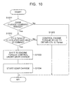
- Fig. 10 is an example of a control flowchart before the gear change;
- Fig. 11 is an example of a control flowchart after the gear change;
- Fig. 12 is an example of an engine torque control performed in step S1105 in Fig. 11;
- Fig. 13 is an example of an engine torque control performed in step S1105 in Fig. 11;
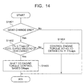
- Fig. 14 is an example of a control flowchart after the gear change;
- Fig. 15 is a schematic view of an example of a detailed entire configuration of an automobile using a control apparatus of the automobile according to the present invention; and
- Fig. 16 is an example of a control flowchart before the gear change.
-
- The embodiment of the present invention is described below with reference to the accompanying drawings.
- Referring to Fig. 1, there is shown a block diagram, in starting a gear change, of an embodiment of the present invention. If a gear change command is outputted from a gear change command output means 1, a torque comparison means 4 performs to compare the current output shaft torque with limit transmission output shaft torque. If the output shaft torque is larger than the limit transmission output shaft torque, a gear change authorization means 2 does not issue the gear change command to a gear change means 3. A torque control means 5 controls the output shaft torque so as to approximate to the limit transmission output shaft torque. This can achieve that, when the output shaft torque drops to the limit transmission output shaft torque or smaller, the gear change authorization means 2 issues a gear change command to the gear change means to start a gear change. This causes the output shaft torque to shift smoothly, thereby enabling a smooth gear change even if the speed is changed in a high output shaft torque condition.
- Referring to Fig. 2, there is shown a block diagram, in completing the gear change, of the embodiment of the present invention. When gear change end detecting means 6 outputs a gear change end signal, the torque comparison means 4 compares the current output shaft torque with target output shaft torque. Unless the output shaft torque is equal to the target output shaft torque, the torque control means 5 controls the output shaft torque so as to approximate to the target output shaft torque. This causes the output shaft torque to shift smoothly, thus enabling a smooth gear change even if the output shaft torque at the completion of the gear change differs from the target output shaft torque.
- Referring to Fig. 3, there is shown an example of an entire detailed configuration of an automobile using a control apparatus of the automobile according to the present invention. In the example shown in Fig. 3, an engine is used as a power generator and a gear transmission is used as power transmitting means.
- A
control unit 405 includes an electronic controlthrottle control unit 401 for controlling anelectronic control throttle 103, anengine control unit 402 for controlling the engine, and atransmission control unit 403 for controlling the transmission. - The
engine 101 includes theelectronic control throttle 103 for adjusting engine torque and anengine revolutions sensor 102 for detecting engine revolutions. Theengine 101 is controlled by anengine control unit 402. Theelectronic control throttle 103 is controlled by an electronic controlthrottle control unit 401. - The gear transmission is constructed to include a starting
clutch 202, a startingclutch actuator 203, awire 204, an input shaft 205, anoutput shaft 301,gears speed dog clutch 220A, a 3- to 4-speed dog clutch 220C, a 6-speed dog clutch 220E, ashift actuator 221, aselect actuator 222,shifter forks change assist clutch 225, a gear changeassist clutch actuator 226, and an outputshaft revolutions sensor 300. The 1- to 2-speed dog clutch 220A comprises aclutch hub 216A, asleeve 217A,synchronizer rings gear splines speed dog clutch 220C includes aclutch hub 216C, asleeve 217C,synchronizer rings 218C and 218D, andgear splines speed dog clutch 220E includes aclutch hub 216E, asleeve 217E, asynchronizer ring 218E, and agear spline 219E. A reverse mechanism is omitted in this diagram. -
Actuators transmission control unit 403 with an oil pressure or a motor. - Engine torque outputted from the
engine 101 is transmitted to the input shaft 205 of the gear transmission via the flywheel 201 and the startingclutch 202, transmitted to theoutput shaft 301 via any one of thegears clutch 202 for transmitting the engine torque to the input shaft 205 of the gear transmission is locked or released by the startingclutch actuator 203 to control transmissibility of the engine torque. - Traveling of one of the 1- to 4-speed and 6-speed is determined by moving any one of the
gears gears 207 and 209 rotatable to theoutput shaft 301 withmoving sleeves claw clutches shifter forks clutch hubs gear splines shift actuator 221 and theselect actuator 222. At this time in order to synchronize theclutch hubs gear splines synchronizer rings - At the 1-speed traveling, a drive shaft torque of the input shaft 205 is transmitted to the
output shaft 301 via the gear 206, thegear 207, and theclutch hub 216A. Thegear 207 is coupled to theclutch hub 216A through thesleeve 217A. At the 2-speed traveling, the drive torque of the input shaft 205 is transmitted to theoutput shaft 301 via thegear 208, the gear 209, and theclutch hub 216A. The gear 209 is coupled to theclutch hub 216A through thesleeve 217A. At the 3-speed traveling, the drive torque of the input shaft 205 is transmitted to theoutput shaft 301 via theclutch hub 216C, thegear 210, and the gear 211. Thegear 210 is coupled to theclutch hub 216C through thesleeve 217C. At the 4-speed traveling, the drive torque of the input shaft 205 is transmitted to theoutput shaft 301 via theclutch hub 216C, thegear 212, and thegear 214. Thegear 212 is coupled to theclutch hub 216C through thesleeve 217C. At the 6-speed traveling, the drive torque of the input shaft 205 is transmitted to theoutput shaft 301 via theclutch hub 216E, thegear 230, and the gear 231. Thegear 230 is coupled to theclutch hub 216E through thesleeve 217E. In this manner, thedog clutches dog clutches - At the 5-speed traveling, the input shaft 205 is fastened to the
gear 214 with the gear change assist clutch 225 before traveling. The gear change assist clutch 225 is driven by the gear change assistclutch actuator 226. During gear shift, the gear change assist clutch 225 is controlled to control the transmission torque, thereby preventing a sense of weakness or an occurrence of blowoff. - The
transmission control unit 403 receives inputs of automobile sensor signals from anaccelerator pedal sensor 406 for detecting an accelerator depression amount, aninhibitor switch 407 for detecting a shift lever position, the outputshaft revolutions sensor 300 for detecting the revolutions of the output shaft, amode switch 408 for changing between an automatic transmission mode and a manual transmission, aplus switch 409 for incrementing the gear change stage by one in the manual transmission mode, and aminus switch 410 for decrementing the gear change stage by one in the manual transmission mode. Thetransmission control unit 403 is coupled to theengine control unit 402 and to the electronic controlthrottle control unit 401 via acommunication line 404 such as control area network (CAN). - The
transmission control unit 403 keeps up on an operational condition on the basis of received signals and controls a starting clutch condition and a gear position to the appropriate ones. The starting clutch 202 controls fastening during fixed-speed traveling or gear change. Thetransmission control unit 403 controls theelectronic control throttle 103 via the electronic controlthrottle control unit 401 so as to prevent theengine 101 from blowing out during gear change in the automatic transmission mode. In addition thetransmission control unit 403 controls theelectronic control throttle 103 and the gear change assist clutch 225 for a smooth change from transmission torque immediately before the gear change to transmission torque immediately after the gear change. Furthermore, it sends a correction value for an ignition timing from thetransmission control unit 403 to theengine control unit 402 to control the ignition timing. If the output shaft torque before the gear change is greater than limit transmission output shaft torque obtained by multiplying a torque capacity of the gear change assist clutch 225 by 5-speed gear ratio, theelectronic control throttle 103 is controlled to absorb the shock caused by a rapid gear change before and after the gear change so as to reduce a sense of discomfort for a driver. - Referring to Fig. 4, there is shown an example of a timing chart of a gear change operation for the gear change assist clutch 225 with large and small torque capacities. Assuming that a low speed corresponds to 1-speed and a high speed to 2-speed, a solid line indicates operations of respective components of a gear change assist clutch having a large torque capacity and a phantom line indicates operations of respective components of a gear change assist clutch having a small torque capacity in the sample gear change of an upshift from the 1-speed to the 2-speed. The abscissa axis corresponds to time. An accelerator pedal position (0) is assumed to be fixed. A throttle opening (1) is assumed to be a function of the accelerator pedal position. For example, the throttle opening TVO is expressed by an equation "TVO = a * accelerator depression amount APS + b" (a and b are constants). Assuming that the throttle opening (1) is fixed during a period from time t0 to time A, engine revolutions (2) and output shaft revolutions (vehicle speed) (3) are increased. If the gear change conditions are fulfilled when the vehicle speed reaches the predetermined speed, a target gear position (6) changes from the 1-speed to the 2-speed at time A to start the gear change operation. The start of the gear change sets 0 to low-speed dog clutch torque (7) with the dog clutch of the 1-speed. At this time, a push load on the gear change assist clutch 225 is increased to transmit gear change assist clutch torque (9) to the output shaft. This push load, which is obtained based on engine torque characteristics, is controlled so that the output shaft torque before a start of the gear change smoothly shifts to the output shaft torque after a completion of the gear change. This control results in a small torque variation of the output shaft torque (10) as Tshock1 in the case of the torque capacity Tqmax1 with the gear change operation completed at time t1. On the other hand, if the torque capacity is Tqmax2 smaller than Tqmax1, the torque variation of the output shaft torque (10) is large as shown in Tshock2 with the gear change operation completed at time t2 later than the time t1. If the torque capacity of the gear change assist clutch is smaller than the output shaft torque as described above, the gear change shock is large and the gear change time is extended, thereby causing a driver to feel odd.
- To solve this problem, there is a method of controlling an electronic control throttle during the gear change operation. Referring to Fig. 5, there is shown an example of a timing chart of a gear change operation for controlling the electronic control throttle during the gear change. The operation up to the time A is the same as for one in Fig. 4. The throttle opening (1) is controlled so as to decrease the engine revolutions (2) quickly from the time A. This results in the gear change operation time of time t3, thus enabling the gear change operation time to be reduced. The gear change shock, however, is the same as the foregoing method and causes a driver to feel odd. The small torque capacity necessarily causes a torque reduction during the gear change in this manner. Therefore in this condition, the electronic control throttle is controlled before and after the gear change so as to minimize variations of the output shaft torque in a short period of time around the gear change. Referring to Fig. 6, there is shown an example of a timing chart of a gear change operation for controlling the electronic control throttle before and after the gear change. When a gear change command is issued, the throttle opening is controlled to drop the output shaft torque smoothly as indicated by a phantom line from time Z to time A. After that, when the output shaft torque drops to a limit transmission output shaft torque Tqmax2 at the time A, the low-speed dog clutch torque is decreased. During the gear change operation, a control operation is performed in the same manner as for one in Fig. 5. After a completion of the gear change at time B, the throttle opening is smoothly returned to one for the target output shaft torque. When the target output shaft torque is obtained at time C, the throttle opening is assumed to be a function of the accelerator pedal position. This control results in a smooth shift of the output shaft torque, thus enabling a smooth gear change even if the output shaft torque is high at the gear change.
- Referring to Fig. 7, there is shown an example of a control flowchart before the gear change. Processing in this flowchart is started at a fixed period on a timer (for example, 10 [ms]). Whether the gear change command is issued is determined in step S701; none is executed unless the command is issued or otherwise the processing progresses to step S702. In the step S702, it is determined whether a current output shaft torque CTo is equal to or smaller than limit transmission output shaft torque Tqmax obtained by multiplying a torque capacity of a gear change assist clutch by a 5-speed gear ratio. If the current output shaft torque is greater than the limit transmission output shaft torque, the processing progresses to step S705 to control the engine torque so that the current output shaft torque decreased to the limit transmission output shaft torque or smaller. If the current output shaft torque is equal to or smaller than the limit transmission output shaft torque, the processing progresses to step S703 to shift to the engine torque control under the gear change and the gear change is started in step S704. This results in a smooth change of the output shaft torque, thereby enabling a smooth gear change even if the output shaft torque before the gear change is greater than the limit transmission output shaft torque.
- Referring to Fig. 8, there is shown an example of an engine torque control operation performed in step S705 in Fig. 7. In step S801, it is determined whether the engine torque control operation is started for the first time after the gear change command is issued. If it is the first time, in step S807 the current output shaft torque CTo at the time when the gear change command is issued is incorporated as an initial value CTo0 and a counter n is initialized to 0. In step S802, it is determined whether the current output shaft torque CTo is equal to or smaller than the limit transmission output shaft torque Tqmax obtained by multiplying the torque capacity of the gear change assist clutch by the 5-speed gear ratio. If the current output shaft torque is greater than the limit transmission output shaft torque, target output shaft torque TTon is evaluated by an equation (1) in step S803, where ti1 indicates a period (for example, 10 [ms]) at which the operation in the step S705 is started and tc1 indicates a control time (for example, 200 [ms]) before the gear change.
- In step S804, a target throttle opening TTVOn is determined on the basis of the target output shaft torque TTon and the current engine revolutions CNe. In step S805, a command is issued so that the current throttle opening is equal to the determined target throttle opening TTVOn. In step S806, the counter n is incremented. This results in a smooth change of the output shaft torque, thus enabling a smooth gear change even if the output shaft torque before the gear change is greater than the limit transmission output shaft torque.
- Referring to Fig. 9, there is shown an example of an engine torque control operation performed in the step S705 in Fig. 7. In step S901, it is determined whether the engine torque control operation is started for the first time after the gear change command is issued. If it is the first time, in step S907 the current output shaft torque CTo at the time when the gear change command is issued is incorporated as an initial value CTo0 and the counter n is initialized to 0. In step S902, it is determined whether the current output shaft torque CTo is equal to or smaller than the limit transmission output shaft torque Tqmax obtained by multiplying the torque capacity of the gear change assist clutch by the 5-speed gear ratio. If the current output shaft torque is greater than the limit transmission output shaft torque, target output shaft torque TTon is evaluated by an equation (2) in step S903, where ti1 indicates a period (for example, 10 [ms]) at which the operation in the step S705 is started and tt1 indicates a time constant (for example, 200 [ms]).
- In step S904, a target throttle opening TTVOn is determined on the basis of the target output shaft torque TTon and the current engine revolutions CNe. In step S905, a command is issued so that the current throttle opening is equal to the determined target throttle opening TTVOn. In step S906, the counter n is incremented. This results in a smooth change of the output shaft torque, thus enabling a smooth gear change even if the output shaft torque before the gear change is greater than the limit transmission output shaft torque.
- Referring to Fig. 10, there is shown an example of a control flowchart before the gear change. Processing in this flowchart is started at a fixed period on the timer (for example, 10 [ms]). Whether the gear change command is issued is determined in step S1001; none is performed unless the command is issued or otherwise the processing progresses to step S1002. In the step S1002, it is determined whether the current output shaft torque CTo is equal to or smaller than the limit transmission output shaft torque Tqmax obtained by multiplying the torque capacity of the gear change assist clutch by the 5-speed gear ratio or whether the time tl1 [s] or more has already elapsed since the gear change command is issued. If the current output shaft torque is greater than the limit transmission output shaft torque and a time tl1 [s] has not elapsed yet since the gear change command is issued, the processing progresses to step S1005 to control the engine torque so that the current output shaft torque decreased to the limit transmission output shaft torque or smaller. If the current output shaft torque is equal to or smaller than the limit transmission output shaft torque or the time tl1 [s] has already elapsed since the gear change command is issued, the processing progresses to step S1003 to shift to the engine torque control under the gear change and the gear change is started in step S1004. This results in a smooth change of the output shaft torque, thereby enabling a smooth gear change even if the output shaft torque before the gear change is greater than the limit transmission output shaft torque. The limit transmission output shaft torque Tqmax set forth in the above necessarily need not be the value obtained by multiplying the torque capacity of the gear change assist clutch by the 5-speed gear ratio, but it is possible to use a value equal to or smaller than the limit transmission output shaft torque Tqmax for the control.
- Referring to Fig. 11, there is shown an example of a control flowchart after the gear change. Processing in this flowchart is started at a fixed period on the timer (for example, 10 [ms]). Whether the gear change is completed is determined in step S1101; none is executed unless it is completed or otherwise the processing progresses to step S1102. In the step S1102, it is determined whether the current output shaft torque CTo is equal to or greater than target output shaft torque Ttoaps evaluated based on the current accelerator pedal position. If the current output shaft torque is smaller than the target output shaft torque, the processing progresses to step S1104 to control the engine torque so that the current output shaft torque increases to the target output shaft torque or higher. If the current output shaft torque is equal to or greater than the target output shaft torque, the processing progresses to step S1103 to shift to the engine torque control based on the accelerator pedal position. This results in a smooth change of the output shaft torque, thereby enabling a smooth gear change even if the output shaft torque after the gear change is smaller than the target output shaft torque based on the accelerator pedal.
- Referring to Fig. 12, there is shown an example of an engine torque control operation performed in step S1104 in Fig. 11. In step S1201, it is determined whether the engine torque control operation is started for the first time after the completion of the gear change. If it is the first time, in step S1207 the current output shaft torque CTo at the time when the gear change is completed is incorporated as an initial value CTo0 and the counter n is initialized to 0. In step S1202, it is determined whether the current output shaft torque CTo is equal to or greater-than the target output shaft torque TToaps obtained based on the accelerator pedal position. If the current output shaft torque is smaller than the target output shaft torque, the target output shaft torque TTon is evaluated by an equation (3) in step S1203, where ti2 indicates a period (for example, 10 [ms]) at which the operation in the step S1104 is started and tc2 indicates a control time (for example, 200 [ms]) after the gear change.
- In step S1204, a target throttle opening TTVOn is determined on the basis of the target output shaft torque TTon and the current engine revolutions CNe. In step S1205, a command is issued so that the current throttle opening is equal to the determined target throttle opening TTVOn. In step S1206, the counter n is incremented. This results in a smooth change of the output shaft torque, thus enabling a smooth gear change even if the output shaft torque after the gear change is smaller than the target output shaft torque based on the accelerator pedal.
- Referring to Fig. 13, there is shown an example of an engine torque control operation performed in the step S1104 in Fig. 11. In step S1301, it is determined whether the engine torque control operation is started for the first time after the gear change is completed. If it is the first time, in step S1307 the current output shaft torque CTo at the time when the gear change is completed is incorporated as an initial value CTo0 and the counter n is initialized to 0. In step S1302, it is determined whether the current output shaft torque CTo is equal to or greater than the target output shaft torque TToaps obtained based on the accelerator pedal position. If the current output shaft torque is smaller than the target output shaft torque, the target output shaft torque TTon is evaluated by an equation (4) in step S1303, where ti2 indicates a period (for example, 10 [ms]) at which the operation in the step S1104 is started and tt2 indicates a time constant (for example, 200 [ms]).
- In step S1304, a target throttle opening TTVOn is determined on the basis of the target output shaft torque TTon and the current engine revolutions CNe. In step S1305, a command is issued so that the current throttle opening is equal to the determined target throttle opening TTVOn. In step S1306, the counter n is incremented. This results in a smooth change of the output shaft torque, thus enabling a smooth gear change even if the output shaft torque after the gear change is smaller than the target output shaft torque based on the accelerator pedal.
- Referring to Fig. 14, there is shown an example of a control flowchart after the gear change. Processing in this flowchart is started at a fixed period on the timer (for example, 10 [ms]). Whether the gear change is completed is determined in step S1401; none is executed unless the gear change is completed or otherwise the processing progresses to step S1402. In the step S1402, it is determined whether the current output shaft torque CTo is equal to or greater than the target output shaft torque TToaps obtained based on the accelerator pedal position or whether the time tl2 [s] or more has already elapsed since the completion of the gear change. If the current output shaft torque is smaller than the target output shaft torque and a time tl2 [s] has not elapsed yet since the completion of the gear change, the processing progresses to step S1404 to control the engine torque so that the current output shaft torque decreased to the target output shaft torque or smaller. If the current output shaft torque is equal to or greater than the target output shaft torque or the time tl2 [s] has already elapsed since the completion of the gear change, the processing progresses to step S1403 to shift to the engine torque control under the gear change. This results in a smooth change of the output shaft torque, thereby enabling a smooth gear change even if the output shaft torque after the gear change is smaller than the target output shaft torque based on the accelerator pedal. Each torque in Figs. 7 to 14 can be replaced by acceleration.
- Referring to Fig. 15, there is shown an example of a detailed entire configuration of an automobile using a control apparatus for the automobile according to the present invention. The automatic transmission in this illustration has a structure in which power from the
engine 101 can be divided into two for a first clutch 1501 and for a second clutch 1502 before input. At all times a 1-speed drive gear 1503 engages with a 1-speed drivengear 1504 and a 3-speed drive gear 1505 engages with a 3-speed drivengear 1506, while the 1-speed drive gear 1503 and the 3-speed drive gear 1505 rotate together with afirst input shaft 1511 if the first clutch 1501 is fastened. The 1-speed drivengear 1504 and the 3-speed drivengear 1506 are fastened to anoutput shaft 1513 through a 1-to 3-speed dog clutch 1514 to transmit the power to a tire. At all times a 2-speed drive gear 1509 engages with a 2-speed drivengear 1510 and a 4-speed drive gear 1507 engages with a 4-speed drivengear 1508, while the 2-speed drive gear 1509 and the 4-speed drive gear 1507 rotate together with asecond input shaft 1512 if the second clutch 1502 is fastened. The 2-speed drivengear 1510 and the 4-speed drivengear 1508 are fastened to theoutput shaft 1513 through a 2- to 4-speed dog clutch 1515 to transmit the power to a tire. In a gear change (for example, 1-speed to 2-speed), the 2-speed drivengear 1510 is fastened from the 1-speed running condition and then the first clutch 1501 is released and the second clutch 1502 is fastened. After that, the 1-speed drivengear 1504 is released. If a torque capacity becomes low due to a deterioration of the first clutch 1501 or the second clutch 1502 in this automatic transmission, perform a control operation as shown in Fig. 16. - Referring to Fig. 16, there is shown an example of a control flowchart before the gear change. Processing in this flowchart is started at a fixed period on the timer (for example, 10 [ms]). Whether the gear change command is issued is determined in step S1601; none is executed unless the command is issued or otherwise the processing progresses to step S1602. In the step S16002, it is determined whether the current output shaft torque CTo is equal to or smaller than the limit transmission output shaft torque Tq1max obtained by multiplying a torque capacity of a target geared clutch selected out of the first clutch and the second clutch by a target gear ratio. If the current output shaft torque is greater than the limit transmission output shaft torque, the processing progresses to step S1605 to control the engine torque so that the current output shaft torque decreased to the limit transmission output shaft torque or smaller. If the current output shaft torque is equal to or smaller than the limit transmission output shaft torque, the processing progresses to step S1603 to shift to the engine torque control under the gear change and the exchange control between the first clutch and the second clutch is started in step S1604. This results in a smooth change of the output shaft torque, thereby enabling a smooth gear change even if the output shaft torque before the gear change is greater than the limit transmission output shaft torque.
Claims (16)
- A control apparatus of an automatic transmission having torque transmission means between an input shaft (205) and an output shaft (301) of a gear transmission with said torque transmission means on at least one gear change stage serving as a friction clutch and said torque transmission means on other gear change stages serving as claw clutches, for controlling said friction clutch at a gear change from one gear change stage to another,
wherein, if output shaft torque exceeds torque generated under a gear change and transmitted by said friction clutch when a gear change command is issued, engine torque is controlled so as to make the output shaft torque appropriate for torque under the gear change transmitted by said friction clutch, and then an engine torque control is switched when the output shaft torque reaches a value appropriate for the torque under the gear change transmitted by said friction clutch to start to change the speed. - A control apparatus of an automatic transmission having torque transmission means between an input shaft (205) and an output shaft (301) of a gear transmission with said torque transmission means on at least one gear change stage serving as a friction clutch and said torque transmission means on other gear change stages serving as claw clutches, for controlling said friction clutch at a gear change from one gear change stage to another, wherein, if output shaft torque exceeds the maximum value of torque under a gear change transmitted by said friction clutch when a gear change command is issued, engine torque is controlled so as to make the output shaft torque decreased to a value equal to or lower than the maximum value of the torque under the gear change transmitted by said friction clutch, and then an engine torque control is switched when the output shaft torque reaches the maximum value of the torque under the gear change transmitted by said friction clutch to start to change the speed.
- A control apparatus of an automatic transmission according to claim 1, wherein the engine torque control is performed by controlling a throttle (103).
- A control apparatus of an automatic transmission according to claim 1, wherein the engine torque is controlled so as to make the output shaft torque near to a predetermined output shaft torque linearly.
- A control apparatus of an automatic transmission according to claim 1, wherein the engine torque is controlled so as to make the output shaft torque near to the predetermined output shaft torque with a primary delay.
- A control apparatus of an automatic transmission according to claim 1, wherein the engine torque is controlled by using an acceleration of a vehicle.
- A control apparatus of an automatic transmission according to claim 1, wherein when a predetermined period of time has elapsed after the issue of the gear change command, the engine torque control is switched to start the gear change.
- A control apparatus of an automatic transmission having torque transmission means between an input shaft (205) and an output shaft (301) of a gear transmission with said torque transmission means on at least one gear change stage serving as a friction clutch and said torque transmission means on other gear change stages serving as claw clutches, for controlling said friction clutch at a gear change from one gear change stage to another,
wherein, if output shaft torque is below target output shaft torque based on an accelerator pedal opening, engine torque is controlled so as to make the output shaft torque increased to a value equal to the target output shaft torque, and then an engine torque control is switched when the output shaft torque reaches the target output shaft torque. - A control apparatus of an automatic transmission according to claim 8, wherein the engine torque control is performed by controlling a throttle (103).
- A control apparatus of an automatic transmission according to claim 8, wherein the engine torque is controlled so as to make the output shaft torque near to the target output shaft torque linearly.
- A control apparatus of an automatic transmission according to claim 8, wherein the engine torque is controlled so as to make the output shaft torque near to the target output shaft torque with a primary delay.
- A control apparatus of an automatic transmission according to claim 8, wherein the engine torque is controlled by using an acceleration of a vehicle.
- A control apparatus of an automatic transmission according to claim 8, wherein the engine torque control is switched when a predetermined period of time has elapsed after the issue of the gear change command.
- A control apparatus of an automatic transmission having a torque transmission system between an input shaft (205) and an output shaft (301) divided into a frist transmission system and a second transmission system each having a combination of claw clutches, with torque transmission systems between an engine (101) and the first transmission system and between the engine (101) and the second transmission system serving as friction clutches, for controlling said friction clutches at a gear change from one gear change stage to another, wherein, if output shaft torque exceeds torque generated under the gear change and transmitted by said friction clutches when a gear change command is issued, engine torque is controlled so as to make the output shaft torque decreased to a value appropriate for the torque generated under the gear change and transmitted by said friction clutches, and then an engine torque control is switched when the output shaft torque reaches the value appropriate for the torque generated under the gear change and transmitted by said friction clutches to start to change the speed.
- A method of controlling an automatic transmission having torque transmission means between an input shaft (205) and an output shaft (301) of a gear transmission with said torque transmission means on at least one gear change stage serving as a friction clutch and said torque transmission means on other gear change stages serving as claw clutches, for controlling said friction clutch at a gear change from one gear change stage to another, wherein, if output shaft torque exceeds torque generated under the gear change and transmitted by said friction clutch when a gear change command is issued, engine torque is controlled so as to make the output shaft torque decreased to a value appropriate for the torque generated under the gear change and transmitted by said friction clutch, and then an engine torque control is switched when the output shaft torque reaches the value appropriate for the torque generated under the gear change and transmitted by said friction clutch to start to change the speed.
- A control apparatus of an automatic transmission having torque transmission means between an input shaft (205) and an output shaft (301) of a gear transmission with said torque transmission means on at least one gear change stage serving as a friction clutch and said torque transmission means on other gear change stages serving as claw clutches, for controlling said friction clutch at a gear change from one gear change stage to another, wherein, if output shaft torque exceeds the torque generated under the gear change and transmitted by said friction clutch when a gear change command is issued, engine torque is controlled so as to achieve a small deviation between the torque generated under the gear change and transmitted by said friction clutch and the output shaft torque before the gear change, and then the engine torque control is switched when the output shaft torque reaches a value appropriate for the torque generated under the gear change and transmitted by said friction clutch to start to change the speed.
Priority Applications (1)
| Application Number | Priority Date | Filing Date | Title |
|---|---|---|---|
| EP03026247A EP1411276A3 (en) | 2000-03-30 | 2001-03-22 | Control apparatus of automatic transmission |
Applications Claiming Priority (2)
| Application Number | Priority Date | Filing Date | Title |
|---|---|---|---|
| JP2000097817A JP2001280175A (en) | 2000-03-30 | 2000-03-30 | Control device and method for automatic transmission using gear mechanism |
| JP2000097817 | 2000-03-30 |
Related Child Applications (1)
| Application Number | Title | Priority Date | Filing Date |
|---|---|---|---|
| EP03026247A Division EP1411276A3 (en) | 2000-03-30 | 2001-03-22 | Control apparatus of automatic transmission |
Publications (1)
| Publication Number | Publication Date |
|---|---|
| EP1138986A1 true EP1138986A1 (en) | 2001-10-04 |
Family
ID=18612389
Family Applications (2)
| Application Number | Title | Priority Date | Filing Date |
|---|---|---|---|
| EP01106438A Withdrawn EP1138986A1 (en) | 2000-03-30 | 2001-03-22 | Apparatus and method for controlling an automatic transmission |
| EP03026247A Withdrawn EP1411276A3 (en) | 2000-03-30 | 2001-03-22 | Control apparatus of automatic transmission |
Family Applications After (1)
| Application Number | Title | Priority Date | Filing Date |
|---|---|---|---|
| EP03026247A Withdrawn EP1411276A3 (en) | 2000-03-30 | 2001-03-22 | Control apparatus of automatic transmission |
Country Status (3)
| Country | Link |
|---|---|
| US (2) | US6514172B2 (en) |
| EP (2) | EP1138986A1 (en) |
| JP (1) | JP2001280175A (en) |
Cited By (1)
| Publication number | Priority date | Publication date | Assignee | Title |
|---|---|---|---|---|
| EP1344965A3 (en) * | 2002-03-15 | 2010-03-24 | Hitachi Ltd. | Method of controlling automobile, automobile control apparatus, transmission, method of controlling transmission and vehicle system |
Families Citing this family (19)
| Publication number | Priority date | Publication date | Assignee | Title |
|---|---|---|---|---|
| WO2001081788A1 (en) * | 2000-04-25 | 2001-11-01 | Hitachi, Ltd. | Automatic transmission |
| JP2002206639A (en) * | 2000-11-08 | 2002-07-26 | Hitachi Ltd | Automatic transmissions and vehicles |
| GB0310482D0 (en) * | 2003-05-07 | 2003-06-11 | Zero Shift Ltd | Shaft engagement mechanism |
| JP4333209B2 (en) * | 2003-05-07 | 2009-09-16 | 株式会社日立製作所 | Automotive control device |
| CA2529279A1 (en) * | 2003-07-08 | 2005-01-20 | Zeroshift Limited | Transmission system |
| GB0510129D0 (en) * | 2005-05-18 | 2005-06-22 | Zeroshift Ltd | Sequential hub layout |
| US7967091B2 (en) * | 2006-11-16 | 2011-06-28 | Ford Global Technologies, Llc | Hybrid electric vehicle powertrain with engine start and transmission shift arbitration |
| JP5041974B2 (en) * | 2006-11-16 | 2012-10-03 | ヤマハ発動機株式会社 | Control system and vehicle |
| GB0623292D0 (en) * | 2006-11-22 | 2007-01-03 | Zeroshift Ltd | Transmission system |
| IT1393610B1 (en) * | 2009-04-06 | 2012-05-08 | Ferrari Spa | METHOD OF CONTROL OF A VEHICLE PROVIDED WITH AN AUTOMATIC MANUAL TRANSMISSION DURING A GEAR SHIFT OR DURING A CHECKOUT |
| US8175781B2 (en) * | 2009-06-17 | 2012-05-08 | GM Global Technology Operations LLC | Torque converter control for variable valve lift powertrain systems |
| DE102009028305A1 (en) * | 2009-08-06 | 2011-02-10 | Zf Friedrichshafen Ag | Method for operating a transmission device of a vehicle drive train |
| US20120103119A1 (en) * | 2010-11-02 | 2012-05-03 | Lin cheng-da | Electrically controlable transmission for controlling the stiffness of a vehicle shock absorber |
| GB201109100D0 (en) | 2011-05-27 | 2011-07-13 | Zeroshift Ltd | Transmission system |
| KR101664545B1 (en) * | 2014-06-03 | 2016-10-11 | 현대자동차주식회사 | Apparatus and method for controlling gear shifting clutch by automated manual transmission |
| US9358981B2 (en) * | 2014-08-21 | 2016-06-07 | Ford Global Technologies, Llc | Methods and system for improving launching of a hybrid vehicle |
| US9573596B2 (en) | 2015-04-28 | 2017-02-21 | Cnh Industrial America Llc | Self-propelled off-road vehicle with system for torque control at shift points |
| US9783188B2 (en) | 2016-01-13 | 2017-10-10 | Ford Global Technologies, Llc | EV mode shift strategy for hybrid vehicle |
| US10000203B2 (en) * | 2016-01-13 | 2018-06-19 | Ford Global Technologies, Llc | EV mode shift strategy for hybrid vehicle |
Citations (5)
| Publication number | Priority date | Publication date | Assignee | Title |
|---|---|---|---|---|
| GB1375467A (en) * | 1972-05-30 | 1974-11-27 | ||
| US4544057A (en) * | 1982-02-05 | 1985-10-01 | Automotive Products Plc | Rotary transmission |
| EP0355576A1 (en) * | 1988-08-08 | 1990-02-28 | Nissan Motor Co., Ltd. | Improved jolt control system for drive system |
| US5091854A (en) * | 1988-05-26 | 1992-02-25 | Mazda Motor Corporation | Control systems for vehicle engines coupled with automatic transmissions |
| US5669849A (en) * | 1995-02-03 | 1997-09-23 | Toyota Jidosha Kabushiki Kaisha | Apparatus for controlling concurrent releasing and engaging actions of frictional coupling devices for shifting vehicle automatic transmission |
Family Cites Families (15)
| Publication number | Priority date | Publication date | Assignee | Title |
|---|---|---|---|---|
| US4905544A (en) * | 1975-09-25 | 1990-03-06 | Ganoung David P | Powertrain control apparatus for improving fuel economy |
| JPS59197658A (en) * | 1983-04-26 | 1984-11-09 | Mazda Motor Corp | Drive controller for car |
| JPS6145163A (en) | 1984-08-10 | 1986-03-05 | Hitachi Ltd | automatic transmission system |
| JPH0623019B2 (en) * | 1984-10-29 | 1994-03-30 | 株式会社島津製作所 | Vehicle acceleration control device |
| JP2764749B2 (en) * | 1989-11-16 | 1998-06-11 | トヨタ自動車株式会社 | Transmission control device for automatic transmission |
| JPH0833175B2 (en) * | 1989-11-24 | 1996-03-29 | 株式会社ユニシアジェックス | Automatic transmission for vehicle |
| US5163530A (en) * | 1989-12-11 | 1992-11-17 | Nissan Motor Company, Limited | Control system for controlling driving torque delivered for driven wheels |
| KR0182775B1 (en) * | 1990-04-18 | 1999-04-01 | 미다 가쓰시게 | Torque control method and apparatus for internal combustion engine and motor vehicles employing the same |
| US5643133A (en) * | 1991-02-25 | 1997-07-01 | Hitachi, Ltd. | Change gear control device using acceleration and gear ratio as parameters for automatic transmission in a motor vehicle and the method therefor |
| JP3318945B2 (en) * | 1992-03-02 | 2002-08-26 | 株式会社日立製作所 | Vehicle control device, vehicle control system and vehicle control method |
| JP3418414B2 (en) * | 1992-03-19 | 2003-06-23 | 株式会社日立製作所 | Internal combustion engine torque control method and torque control device |
| JPH0672187A (en) * | 1992-05-28 | 1994-03-15 | Mitsubishi Electric Corp | Engine control device for vehicle with automatic transmission and control method thereof |
| JP3523003B2 (en) * | 1997-02-06 | 2004-04-26 | ジヤトコ株式会社 | Control device for automatic transmission |
| JPH11198686A (en) * | 1998-01-09 | 1999-07-27 | Honda Motor Co Ltd | Vehicle driving force control device |
| JP3649004B2 (en) * | 1998-10-30 | 2005-05-18 | アイシン・エィ・ダブリュ株式会社 | Shift control device for automatic transmission |
-
2000
- 2000-03-30 JP JP2000097817A patent/JP2001280175A/en active Pending
-
2001
- 2001-02-26 US US09/792,032 patent/US6514172B2/en not_active Expired - Fee Related
- 2001-03-22 EP EP01106438A patent/EP1138986A1/en not_active Withdrawn
- 2001-03-22 EP EP03026247A patent/EP1411276A3/en not_active Withdrawn
-
2002
- 2002-11-20 US US10/300,018 patent/US6705971B2/en not_active Expired - Fee Related
Patent Citations (5)
| Publication number | Priority date | Publication date | Assignee | Title |
|---|---|---|---|---|
| GB1375467A (en) * | 1972-05-30 | 1974-11-27 | ||
| US4544057A (en) * | 1982-02-05 | 1985-10-01 | Automotive Products Plc | Rotary transmission |
| US5091854A (en) * | 1988-05-26 | 1992-02-25 | Mazda Motor Corporation | Control systems for vehicle engines coupled with automatic transmissions |
| EP0355576A1 (en) * | 1988-08-08 | 1990-02-28 | Nissan Motor Co., Ltd. | Improved jolt control system for drive system |
| US5669849A (en) * | 1995-02-03 | 1997-09-23 | Toyota Jidosha Kabushiki Kaisha | Apparatus for controlling concurrent releasing and engaging actions of frictional coupling devices for shifting vehicle automatic transmission |
Cited By (1)
| Publication number | Priority date | Publication date | Assignee | Title |
|---|---|---|---|---|
| EP1344965A3 (en) * | 2002-03-15 | 2010-03-24 | Hitachi Ltd. | Method of controlling automobile, automobile control apparatus, transmission, method of controlling transmission and vehicle system |
Also Published As
| Publication number | Publication date |
|---|---|
| US20030069107A1 (en) | 2003-04-10 |
| EP1411276A2 (en) | 2004-04-21 |
| US6705971B2 (en) | 2004-03-16 |
| US20010027689A1 (en) | 2001-10-11 |
| JP2001280175A (en) | 2001-10-10 |
| US6514172B2 (en) | 2003-02-04 |
| EP1411276A3 (en) | 2005-09-14 |
Similar Documents
| Publication | Publication Date | Title |
|---|---|---|
| EP1138986A1 (en) | Apparatus and method for controlling an automatic transmission | |
| JP3499852B2 (en) | Power transmission mechanism | |
| JP3502058B2 (en) | Automatic transmission | |
| JP2001141047A (en) | Control device for synchronous mesh automatic transmission | |
| JP2003314635A (en) | Automatic transmission | |
| US6603214B1 (en) | Control equipment for a vehicle and control method thereof | |
| JP4887058B2 (en) | Control apparatus and control method for automobile | |
| RU2338099C2 (en) | Gearshift anti-jerk device | |
| JP2004516999A (en) | Power system control and adjustment method | |
| WO2003040594A1 (en) | Gear type speed change unit control device, control method, and automobile | |
| EP1508468B1 (en) | Control apparatus and control method for a changeover gear | |
| JP4007321B2 (en) | Automotive control device | |
| JPH0989090A (en) | Synchronization control device for vehicle | |
| JP4701957B2 (en) | Shift end determination device | |
| JP2010096235A (en) | Control device of clutch | |
| JP2002257225A (en) | Control device for automatic transmission | |
| JP2003156137A (en) | Vehicle shift control method and vehicle shift control device | |
| JP4457094B2 (en) | Start control device and start control method for twin clutch transmission | |
| JPS6353411B2 (en) | ||
| CN112576739B (en) | Method for automatically controlling a drivetrain having a servo-assisted gearbox | |
| KR100716626B1 (en) | Double Clutch Driving Method for Automatic Transmission | |
| EP0698754B1 (en) | Control system for automatic transmission for vehicle | |
| JP2000097319A (en) | Method and apparatus for downshifting an automotive transmission | |
| JP2004011695A (en) | Synchronous mesh type automatic transmission | |
| JP4792837B2 (en) | Actuator stroke amount determination device |
Legal Events
| Date | Code | Title | Description |
|---|---|---|---|
| PUAI | Public reference made under article 153(3) epc to a published international application that has entered the european phase |
Free format text: ORIGINAL CODE: 0009012 |
|
| AK | Designated contracting states |
Kind code of ref document: A1 Designated state(s): AT BE CH CY DE DK ES FI FR GB GR IE IT LI LU MC NL PT SE TR Kind code of ref document: A1 Designated state(s): DE FR GB IT |
|
| AX | Request for extension of the european patent |
Free format text: AL;LT;LV;MK;RO;SI |
|
| 17P | Request for examination filed |
Effective date: 20020125 |
|
| AKX | Designation fees paid |
Free format text: DE FR GB IT |
|
| 17Q | First examination report despatched |
Effective date: 20030606 |
|
| GRAP | Despatch of communication of intention to grant a patent |
Free format text: ORIGINAL CODE: EPIDOSNIGR1 |
|
| STAA | Information on the status of an ep patent application or granted ep patent |
Free format text: STATUS: THE APPLICATION IS DEEMED TO BE WITHDRAWN |
|
| 18D | Application deemed to be withdrawn |
Effective date: 20060225 |