EP1138983A2 - Gear drive mechanism for office products - Google Patents
Gear drive mechanism for office products Download PDFInfo
- Publication number
- EP1138983A2 EP1138983A2 EP01106931A EP01106931A EP1138983A2 EP 1138983 A2 EP1138983 A2 EP 1138983A2 EP 01106931 A EP01106931 A EP 01106931A EP 01106931 A EP01106931 A EP 01106931A EP 1138983 A2 EP1138983 A2 EP 1138983A2
- Authority
- EP
- European Patent Office
- Prior art keywords
- gear
- shaft
- drive mechanism
- washer
- shafts
- Prior art date
- Legal status (The legal status is an assumption and is not a legal conclusion. Google has not performed a legal analysis and makes no representation as to the accuracy of the status listed.)
- Granted
Links
Images


Classifications
-
- F—MECHANICAL ENGINEERING; LIGHTING; HEATING; WEAPONS; BLASTING
- F16—ENGINEERING ELEMENTS AND UNITS; GENERAL MEASURES FOR PRODUCING AND MAINTAINING EFFECTIVE FUNCTIONING OF MACHINES OR INSTALLATIONS; THERMAL INSULATION IN GENERAL
- F16H—GEARING
- F16H57/00—General details of gearing
- F16H57/02—Gearboxes; Mounting gearing therein
- F16H57/021—Shaft support structures, e.g. partition walls, bearing eyes, casing walls or covers with bearings
-
- B—PERFORMING OPERATIONS; TRANSPORTING
- B41—PRINTING; LINING MACHINES; TYPEWRITERS; STAMPS
- B41J—TYPEWRITERS; SELECTIVE PRINTING MECHANISMS, i.e. MECHANISMS PRINTING OTHERWISE THAN FROM A FORME; CORRECTION OF TYPOGRAPHICAL ERRORS
- B41J3/00—Typewriters or selective printing or marking mechanisms characterised by the purpose for which they are constructed
- B41J3/407—Typewriters or selective printing or marking mechanisms characterised by the purpose for which they are constructed for marking on special material
- B41J3/4075—Tape printers; Label printers
-
- F—MECHANICAL ENGINEERING; LIGHTING; HEATING; WEAPONS; BLASTING
- F16—ENGINEERING ELEMENTS AND UNITS; GENERAL MEASURES FOR PRODUCING AND MAINTAINING EFFECTIVE FUNCTIONING OF MACHINES OR INSTALLATIONS; THERMAL INSULATION IN GENERAL
- F16B—DEVICES FOR FASTENING OR SECURING CONSTRUCTIONAL ELEMENTS OR MACHINE PARTS TOGETHER, e.g. NAILS, BOLTS, CIRCLIPS, CLAMPS, CLIPS OR WEDGES; JOINTS OR JOINTING
- F16B2200/00—Constructional details of connections not covered for in other groups of this subclass
- F16B2200/69—Redundant disconnection blocking means
-
- Y—GENERAL TAGGING OF NEW TECHNOLOGICAL DEVELOPMENTS; GENERAL TAGGING OF CROSS-SECTIONAL TECHNOLOGIES SPANNING OVER SEVERAL SECTIONS OF THE IPC; TECHNICAL SUBJECTS COVERED BY FORMER USPC CROSS-REFERENCE ART COLLECTIONS [XRACs] AND DIGESTS
- Y10—TECHNICAL SUBJECTS COVERED BY FORMER USPC
- Y10T—TECHNICAL SUBJECTS COVERED BY FORMER US CLASSIFICATION
- Y10T74/00—Machine element or mechanism
- Y10T74/19—Gearing
- Y10T74/1956—Adjustable
-
- Y—GENERAL TAGGING OF NEW TECHNOLOGICAL DEVELOPMENTS; GENERAL TAGGING OF CROSS-SECTIONAL TECHNOLOGIES SPANNING OVER SEVERAL SECTIONS OF THE IPC; TECHNICAL SUBJECTS COVERED BY FORMER USPC CROSS-REFERENCE ART COLLECTIONS [XRACs] AND DIGESTS
- Y10—TECHNICAL SUBJECTS COVERED BY FORMER USPC
- Y10T—TECHNICAL SUBJECTS COVERED BY FORMER US CLASSIFICATION
- Y10T74/00—Machine element or mechanism
- Y10T74/19—Gearing
- Y10T74/19642—Directly cooperating gears
- Y10T74/19647—Parallel axes or shafts
-
- Y—GENERAL TAGGING OF NEW TECHNOLOGICAL DEVELOPMENTS; GENERAL TAGGING OF CROSS-SECTIONAL TECHNOLOGIES SPANNING OVER SEVERAL SECTIONS OF THE IPC; TECHNICAL SUBJECTS COVERED BY FORMER USPC CROSS-REFERENCE ART COLLECTIONS [XRACs] AND DIGESTS
- Y10—TECHNICAL SUBJECTS COVERED BY FORMER USPC
- Y10T—TECHNICAL SUBJECTS COVERED BY FORMER US CLASSIFICATION
- Y10T74/00—Machine element or mechanism
- Y10T74/19—Gearing
- Y10T74/19851—Gear and rotary bodies
Definitions
- the invention relates to a gear drive mechanism that drives a drive shaft in an office product, more particularly, to a gear drive mechanism that is provided with a removal preventive after a gear is fit to a cantilever-like shaft.
- label writers that print characters and the like on a label tape as conventional office products.
- a cassette in which the label tape is wound is installed.
- the label writer feeds the label tape from the cassette to a print head.
- the label writer prints characters and the like on the label tape by the print head and a platen roller and discharges the printed label tape outside a main body by a nip roller.
- Such a series of driving in the label writer is performed by a gear drive mechanism provided in the main body of the label writer under the cassette.
- the gear drive mechanism is structured such that a plurality of shafts including a drive shaft cantilevers from a base plate, gears are fit into the respective shafts, the gears fit into each shafts are engaged with each other, and the gears are prevented from coming off from the shafts .
- a general method for preventing the gears from coming off is that a groove is formed around an end of the shaft and a removal preventive washer is fit into the groove.
- an E-shaped removal preventive clip that is an elastic metal plate is used for the removal preventive washer.
- the E-shaped removal preventive clip is shaped like a letter C having a protrusion at the center.
- the E-shaped removal preventive clip has an opening with respect to the shaft, so that the E-shaped removal preventive clip can be easily attached/detached to/from the shaft.
- This invention provides a gear drive mechanism that is easy to be disassembled and contributes to miniaturization of the office products by thinning the gear drive mechanism.
- a gear drive mechanism for office products of claim 1 that drives a specific shaft by which a plurality of shafts cantilever from a base plate attached within the office product, and gears are fit to the shafts and engaged with each other, is characterized in that a groove is formed around an end of at least one of the shaft other than the specific shaft, a washer having a ring-shaped and a slit in a direction of diameter is fit in the groove as a removal preventive of the gear, and a recessed portion is provided in a part of a side surface of the gear throughout the washer.
- the gear can be prevented from coming off by using the thin ring-shaped washer having a simple structure and the slit in the direction of diameter. Because the washer has the simple structure, a diameter and length of the shaft can be minimized using the washer conforming to the shaft. Further, the gear drive mechanism can be easily disassembled by which the slit in the washer is aligned with the recessed portion provided to the side surface of the gear and then a tool is inserted in the recessed portion.
- the gear can be prevented from coming off by using the thin ring-shaped washer having a simple structure and the slit in the direction of diameter. Therefore, the gear drive mechanism can be thin, so that the office products can be downsized. Further, the gear drive mechanism can be easily disassembled by which the slit in the washer is aligned with the recessed portion provided to the side surface of the gear and then a tool is inserted in the recessed portion.
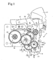
- FIG. 1 is a diagram showing a structure of a gear drive mechanism 1 installed in an office product.
- FIG. 2 is an enlarged sectional view showing a structure of a gear removal preventive 17 of the gear drive mechanism 1.
- FIG. 3 is a perspective view of a washer 25 used in the gear removal preventive 17.
- the gear drive mechanism 1 shown in FIG. 1, for example, is applied to a label writer X shown in FIG. 4, which is an office product, as its drive mechanism.
- the label writer X feeds a label tape from a label cassette and prints characters and the like on the label tape.
- the gear drive mechanism 1 includes a plurality of shafts, a first shaft 2 to a seventh shaft 8; a plurality of gears, a first gear 9 to a seventh gear 15, which are fit into the respective shafts; and the gear removal preventive 17 for the first gear 9 of the first shaft 2 and the third gear 11 of the third gear 4.
- These members 2 to 15 and 17 are provided on a base plate 18.
- the first gear 2 to seventh gear 8 upwardly protrude from the base plate 18 in parallel.
- the fourth gear 5 is a take-up shaft of the label cassette and a drive shaft.
- the sixth shaft 7 is a drive shaft for driving a tape feed roller cam 36 provided to the label cassette.
- the first gear 9 to seventh gear 15 shown in the drawing are fit into the first shaft 2 to the seventh shaft 8, respectively.
- the first gear 9 including a small-diameter gear 9A and a large-diameter gear 9B integrated in this order from the base plate 18 side is fit and the removal preventive 17 described later is provided to the shaft at its end.
- the large-diameter gear 9B of the first gear 9 engages an output gear 22 of the DC motor 19.
- the second gear 10 including a large-diameter gear 10B and a small-diameter gear 10A integrated in this order from the base plate 18 side is fit.
- the large-diameter gear 10A of the second gear 10 engages the small-diameter 9B of the first gear 9.
- the large-diameter gear 10A of the second gear 10 is prevented from coming off because the large-diameter gear 10 A is sandwiched between the large-diameter gear 9B of the first gear 9 and the base plate 18.
- the third gear 11 including a small-diameter gear 11A and a large-diameter gear 11B integrated in this order from the base plate 18 side is fit and the removal preventive 17 is provided to the shaft at its end.
- the large-diameter gear 11B of the third gear 11 engages the small-diameter gear 10B of the second gear 10.
- the fourth gear 12 and a take-up shaft 28 are fit in this order from the base plate 18 side.
- the fourth gear 12 engages the large-diameter gear 11B of the third gear 11.
- the fourth shaft 5 and the take-up shaft 28 protrude toward you and engage the cassette.
- the E-shaped removal preventive clip described above is fit to the end of the fourth shaft 5. Therefore, the fourth gear 12 and the take-up shaft 28 is prevented from coming off from the forth shaft 5.
- the fifth gear 13 is fit in line with the base plate 18.
- the fifth gear 13 engages the small-diameter gear 11A of the third gear 11.
- the fifth gear 13 is prevented from coming off because the fifth gear 13 is sandwiched between the large-diameter gear 11B of the third gear 11 and the base plate 18.
- the sixth gear 14 is fit in line with the base plate 18.
- the seventh gear 15 is fit in line with the base plate 18.
- the sixth gear 14 and the seventh gear 15 engage the fifth gear 13.
- the sixth gear 14 and the seventh gear 15 each has collar 16, 16.
- the sixth gear 14 and the seventh gear 15 are prevented from coming off because the collars 16, 16 of the sixth gear 14 and the seventh gear 15 are sandwiched between the lower surface of the fifth gear 13 and the base plate 18.
- the gear drive mechanism 1 transmits rotation of the DC motor 19 to the gear 12 via the gears 9, 10, 11 while reducing its speed, and rotates and drives the tape feed roller cam 36 and the seventh gear 15 via the gears 11 to 13 while rotating and driving the take-up shaft 28.
- the seventh gear 15 rotates and drives the platen roller 20 via a gear not shown which is provided under the platen roller 20 on the same shaft as the platen roller 20 so that the gear can rotate together with the platen roller 20.
- the gear removal preventive 17 is applied to the first shaft 2 and the third shaft 4 that are countershafts and prevent the gear from coming out at the end.
- the gear removal preventive 17 for the third shaft 4 includes a removal preventive groove 23, an insertion groove 24, and a washer 25.
- the removal preventive groove 23 is a circular groove formed around the end of the third shaft 4.
- the insertion groove 24 is formed in a side surface of the large-diameter gear 11B of the fourth gear 11.
- the insertion groove 24 is formed around the third shaft 4, extending in a direction of the diameter.
- the washer 25 is formed in a ring shape and has a slit 26 extending in the direction of diameter.
- the washer 25 is made of resin, such as plastic material, so that the thickness of the washer 25 can be 0.25 mm or less.
- the width of the removal preventive groove 23 and the insertion groove 24 of FIG. 2 is also formed so as to be the same dimension as the thickness of the washer 25.
- the washer 25 is fit in the removal preventive groove 23 using the slit 26 with elastically deformed as shown by double dashed chain line. At the same time, the washer is installed in the insertion groove 24 by releasing the elastic deformation.
- the removal preventive 17 for the first shaft 2 has the same structure as that of the removal preventive 17 for the third shaft 4, except that the removal preventive 17 for the first shaft 2 has no insertion groove 24.
- the first gear 9 and the forth gear 11 are prevented from coming off from the first shaft 2 and the third shaft 4, respectively. Because the fourth gear 11 is prevented from coming off, the second gear 10 and the fifth gear 13 provided under the fourth gear 11 are also prevented from coming off the shafts.
- the washer 25 is detachable from the fourth gear 11 using a recessed portion 27.
- the recessed portion 27 is formed within the insertion groove 24 provided in the side surface of the fourth gear 12 and outwardly extends in the direction of diameter of the fourth gear 11 from the third shaft 4.
- the slot 26 is positioned over/near the recessed portion 27.
- a slim tool is inserted into the recessed portion 27 and the washer 25 is lifted from the fourth gear 11.
- the washer 25 is vertically stretched at the slit 26 as a boundary.
- the washer 25 can be removed from the removal preventive groove 23 by moving the tool along the shaft.
- the washer 25 for the first gear 9 can be also removed from the first shaft 2 in the same manner.
- the gears 9 to 15 can be prevented from coming off using the thin washer 25.
- the washer 25 is made of plastic material, the washer can be thin, that is, the thickness of the washer can be 0.25 mm or less. Therefore, the removal prevention groove 23 of the third shaft 4 and the first shaft 2 can be also narrow conforming to the thickness of the washer 25. The amount of protrusion of the third shaft 4 and the first shaft 2 from the fourth gear 11 and the first gear 9 can be restricted to a minimum. Accordingly, the thickness of the gear drive mechanism 1 can be reduced.
- the washer 25 By inserting the slim tool into the recessed portion 27, the washer 25 can be easily removed from the fourth gear 12 and the first gear 9 and the gears 9 to 15 can be disassembled.
- the gear drive mechanism 1 is applied to the label writer X, which is the office product, as a drive mechanism.
- the label writer X includes a lid 31 and a main body 32.
- the lid 31 is provided to the main body 32 by hinges and freely covers and uncovers the main body 32.
- the lid 31 is provided with a keyboard for inputting data of characters.
- a control circuit board that processes the data, the gear drive mechanism 1, the DC motor 19, the platen roller 20 and the print head 42 are provided.
- the gear drive mechanism 1 is attached to the bottom of the main body 32 so as to be under a cover 33 provided in the main body 32.
- a cover 33 provided in the main body 32.
- an opening 34 is formed so that the take-up shaft 28 of the fourth shaft 5 passes therethrough.
- the label cassette 35 is installed on the upper side of the cover 33.
- the label cassette 35 is engaged with the take-up shaft 28 protruding from the cover 33 and then installed in the main body 32.
- the label tape is housed in the label cassette 35 in a wound state.
- the label writer X feeds the label tape to the print head 42 from the label cassette 35 and prints input characters and the like onto the label tape using the print head 42 and the platen roller 20 by driving the gear drive mechanism 1 by the DC motor 19. Then, the label writer X discharges the printed label tape outside of the main body 32 by the tape feed roller cam 36 provided to the end of the sixth shaft 7 and the feed roller 21 and cuts the label tape by pressing the lever 43 for moving the cutter.
- the gear drive mechanism 1 of the embodiment of the invention when the gear drive mechanism 1 of the embodiment of the invention is applied to the label writer X that is the office product, the gear drive mechanism 1 can become thin so that the label writer X can be also thin. Therefore, a downsizing of the label writer X can be achieved.
- the ends of the shafts, except for the fourth shaft 5 that is the take-up shaft, are covered with the cover 33. Therefore, the ends of the shafts are hidden, so that the inside of the main body 32 of the label writer X is visually simplified. Further, the gear drive mechanism 1 is thin, so that the space for the cassette installation is provided over the gear drive mechanism 1 and the cover 33.
- the gear drive mechanism 1 of the embodiment of the invention has been described using an example that the gear drive mechanism 1 is applied to the label writer X.
- the invention is not restricted to the embodiment described above.
- the gear drive mechanism 1 can be also applied to other office products, such as printers and facsimile machines.
- the gear drive mechanism 1 is applied to the small office products, the internal space in the main body can be made effective use.
- the removal preventive 17 including the washer 25 is applied to the first shaft 2 and the third shaft 4. Because the largest gear is fit into the third shaft 4, the removal preventive 17 using the washer 25 is applied to only the third shaft 4. As a result, the thickness of the gear fit to the first shaft 2 becomes thin, so that the removal preventive 17 using the specified E-shaped removal preventive washer can be used. Further, the number of shafts and gears structuring the gear drive mechanism 1 and an arrangement are not restricted to the structure of FIG. 1.
Landscapes
- Engineering & Computer Science (AREA)
- General Engineering & Computer Science (AREA)
- Mechanical Engineering (AREA)
- Gear Transmission (AREA)
- Gears, Cams (AREA)
Abstract
Description
Claims (3)
- A gear drive mechanism for office products that drives a specific shaft by which a plurality of shafts cantilever from a base plate attached within the office product, and gears are fit to the shafts and engaged with each other
characterized in that a groove is formed around an end of at least one of the shaft other than the specific shaft, a washer having a ring-shaped and a slit in a direction of diameter is fit in the groove as a removal preventive of the gear, and a recessed portion is provided in a part of a side surface of the gear throughout the washer. - The gear drive mechanism for the office products claimed in claim 1,
characterized in that the washer is made of plastic and is 0.25 mm or less in thickness. - The gear drive mechanism for the office products claimed in claim 1 or 2,
characterized in that a cover having an opening through which the drive shaft passes is attached so as to be opposed to the base plate.
Applications Claiming Priority (2)
| Application Number | Priority Date | Filing Date | Title |
|---|---|---|---|
| JP2000101171 | 2000-03-31 | ||
| JP2000101171A JP2001280448A (en) | 2000-03-31 | 2000-03-31 | Office equipment gear drive mechanism |
Publications (3)
| Publication Number | Publication Date |
|---|---|
| EP1138983A2 true EP1138983A2 (en) | 2001-10-04 |
| EP1138983A3 EP1138983A3 (en) | 2001-11-14 |
| EP1138983B1 EP1138983B1 (en) | 2004-06-02 |
Family
ID=18615264
Family Applications (1)
| Application Number | Title | Priority Date | Filing Date |
|---|---|---|---|
| EP01106931A Expired - Lifetime EP1138983B1 (en) | 2000-03-31 | 2001-03-20 | Gear drive mechanism for office products |
Country Status (4)
| Country | Link |
|---|---|
| US (1) | US6792823B2 (en) |
| EP (1) | EP1138983B1 (en) |
| JP (1) | JP2001280448A (en) |
| DE (1) | DE60103579T2 (en) |
Families Citing this family (12)
| Publication number | Priority date | Publication date | Assignee | Title |
|---|---|---|---|---|
| JP2005257072A (en) * | 2004-02-12 | 2005-09-22 | Seiko Instruments Inc | Gear transmission and electronic device |
| US7491148B2 (en) * | 2004-06-18 | 2009-02-17 | Autocraft Industries, Inc. | System for improving the refurbishing of a transmission |
| US8800401B2 (en) * | 2008-07-31 | 2014-08-12 | Deere & Company | Transmission gear engagement mechanism and method of operation |
| DE102009028380B4 (en) * | 2009-08-10 | 2015-05-07 | Zf Lenksysteme Gmbh | Device for pressing a screw |
| USD690192S1 (en) | 2011-07-13 | 2013-09-24 | Smc Kabushiki Kaisha | Internal snap member |
| USD690191S1 (en) * | 2011-07-13 | 2013-09-24 | Smc Kabushiki Kaisha | Internal snap member |
| USD688123S1 (en) | 2011-07-13 | 2013-08-20 | Smc Kabushiki Kaisha | Internal snap member |
| JP5975436B2 (en) * | 2012-05-30 | 2016-08-23 | 極東産機株式会社 | Automatic wallpaper pasting machine |
| CN103899711B (en) * | 2012-12-28 | 2016-12-28 | 中山市云创知识产权服务有限公司 | Back gear |
| DE102016207155A1 (en) * | 2016-04-27 | 2017-11-02 | Bühler Motor GmbH | actuator |
| DE102018110879B4 (en) * | 2018-05-07 | 2025-05-08 | Schaeffler Technologies AG & Co. KG | Arrangement for securing the axial position of a sun gear of a planetary gear stage on a rotor shaft of an electrical machine and use of such an arrangement |
| US11622598B2 (en) * | 2021-08-16 | 2023-04-11 | Orthofeet, Inc. | Easy-entry shoe with a spring-flexible rear |
Family Cites Families (34)
| Publication number | Priority date | Publication date | Assignee | Title |
|---|---|---|---|---|
| US2026454A (en) * | 1933-01-10 | 1935-12-31 | Seidel & Naumann Ag | Locking disk |
| CH282171A (en) * | 1948-07-07 | 1952-04-15 | Honegger Willy | Device for connecting two parts to one another. |
| US2886355A (en) * | 1955-08-09 | 1959-05-12 | Waldes Kohinoor Inc | Coupled assemblies and coupling ring for use therein |
| US2834620A (en) * | 1956-05-14 | 1958-05-13 | Gen Electric | Improved rotative drive assembly |
| US3340760A (en) * | 1965-05-05 | 1967-09-12 | Markite Corp | Means for preventing axial movement of a shaft or stud |
| DE1450966A1 (en) * | 1965-05-07 | 1969-05-14 | Walter Engelmann | Lock washer open on one side |
| US3396554A (en) * | 1966-04-14 | 1968-08-13 | Gen Motors Corp | Retaining ring for a universal joint member |
| US3469494A (en) * | 1966-12-12 | 1969-09-30 | Eaton Yale & Towne | Internal retaining ring |
| US3588154A (en) * | 1968-10-29 | 1971-06-28 | Bendix Corp | Torque coupling device |
| US3531144A (en) * | 1969-02-27 | 1970-09-29 | Ingersoll Rand Co | Retainer ring |
| US3595123A (en) * | 1969-08-25 | 1971-07-27 | Waldes Kohinoor Inc | Radial assembly-tire spring retaining rings |
| US3992117A (en) * | 1975-03-27 | 1976-11-16 | General Motors Corporation | Shaft retaining ring |
| US4124318A (en) * | 1978-03-23 | 1978-11-07 | General Motors Corporation | Splined assembly with retaining rings |
| US4405251A (en) * | 1980-03-06 | 1983-09-20 | Miller Fluid Power Corporation | Retaining ring locking device |
| US4470735A (en) * | 1981-12-21 | 1984-09-11 | United Technologies Corporation | Self-locking bolt |
| US4692079A (en) * | 1984-09-14 | 1987-09-08 | Waldes Truarc Inc. | Bowed internal spring retaining ring that functions regardless of its orientation when installed in a groove |
| US4630506A (en) * | 1984-12-06 | 1986-12-23 | Dana Corporation | Drive axle and method of assembling same |
| US5094117A (en) * | 1990-12-26 | 1992-03-10 | Chrysler Corporation | Infinitely adjustable bolt locking plate |
| US5131894A (en) * | 1991-02-27 | 1992-07-21 | Dana Corporation | Axle shaft retainer of use in differential case |
| US5127764A (en) * | 1991-04-24 | 1992-07-07 | Shop Vac Corporation | Clip ring spread preventer |
| JPH0658376A (en) * | 1992-08-07 | 1994-03-01 | Matsushita Graphic Commun Syst Inc | Driving force transmitting device |
| JPH0658737A (en) | 1992-08-10 | 1994-03-04 | Nippon Telegr & Teleph Corp <Ntt> | Three dimensional body discrimination device |
| DE4229726C2 (en) * | 1992-09-05 | 1996-05-23 | Gkn Automotive Ag | Arrangement of drive shaft and slid on hub |
| KR0122443B1 (en) * | 1993-09-28 | 1997-11-17 | 김광호 | Facsimile device for general paper |
| US5620388A (en) * | 1995-03-03 | 1997-04-15 | Ford Motor Company | Axle axial motion limiting device for a rotating component shaft position adjustment |
| US5762173A (en) * | 1995-04-25 | 1998-06-09 | Mita Industrial Co., Ltd. | Electromagnetic clutch |
| JPH09242851A (en) * | 1996-03-07 | 1997-09-16 | Tec Corp | Power transmission device |
| US5671640A (en) * | 1996-04-30 | 1997-09-30 | Tractech Inc. | Locking differential with pre-load means and C-clip retainers |
| JP3576730B2 (en) * | 1996-12-25 | 2004-10-13 | スター精密株式会社 | Printer |
| US6014916A (en) * | 1998-05-05 | 2000-01-18 | Vehicular Technologies, Inc. | Two part pinion pin for a differential assembly |
| US6070945A (en) * | 1998-07-15 | 2000-06-06 | Kennametal Inc. | Cutting tool retainer |
| US6116809A (en) * | 1998-08-26 | 2000-09-12 | General Motors Corporation | Rotating assembly with internal retaining ring |
| US6490426B1 (en) * | 2000-11-03 | 2002-12-03 | Xerox Corporation | Modular imaging member flange assembly |
| US6557947B1 (en) * | 2001-04-27 | 2003-05-06 | Torque-Traction Technologies, Inc. | Three quarter floating automotive axle |
-
2000
- 2000-03-31 JP JP2000101171A patent/JP2001280448A/en active Pending
-
2001
- 2001-03-20 DE DE60103579T patent/DE60103579T2/en not_active Expired - Lifetime
- 2001-03-20 EP EP01106931A patent/EP1138983B1/en not_active Expired - Lifetime
- 2001-03-22 US US09/813,863 patent/US6792823B2/en not_active Expired - Lifetime
Also Published As
| Publication number | Publication date |
|---|---|
| DE60103579D1 (en) | 2004-07-08 |
| EP1138983A3 (en) | 2001-11-14 |
| JP2001280448A (en) | 2001-10-10 |
| EP1138983B1 (en) | 2004-06-02 |
| DE60103579T2 (en) | 2005-06-16 |
| US20010026719A1 (en) | 2001-10-04 |
| US6792823B2 (en) | 2004-09-21 |
Similar Documents
| Publication | Publication Date | Title |
|---|---|---|
| EP1138983B1 (en) | Gear drive mechanism for office products | |
| EP0598418B1 (en) | A tape supply cartridge for a thermal printing device | |
| EP1052107B1 (en) | Thermal printer | |
| JP4492125B2 (en) | Roll sheet holder and tape printer | |
| JP2009107287A (en) | Printing device | |
| US5254200A (en) | Method and apparatus for peeling a releasable sheet from an adhesive label | |
| JPH06122239A (en) | Printing sheet cartridge and printing equipment | |
| JP4487953B2 (en) | Image forming apparatus | |
| EP1504913A1 (en) | Tape printing apparatus having a tape discharge mechanism and method of discharging a tape | |
| JP2005212139A (en) | Label printer | |
| EP0046893A2 (en) | Shingler wheel for sheet feed apparatus and sheet feed apparatus comprising the same | |
| JP2001001292A (en) | Recording material cutting device | |
| US5702189A (en) | Rack and pinion cleaning mechanism in a serial printer | |
| KR200309793Y1 (en) | The bar code printer | |
| JP3753573B2 (en) | Printing device and printing control method | |
| JP3864066B2 (en) | Tape printer | |
| JP3041381U (en) | Tape cartridge | |
| JPS5935406Y2 (en) | Printer paper tension adjustment device | |
| JPS6021273A (en) | Printing apparatus | |
| JP3481827B2 (en) | Tape cartridge | |
| JPH056132Y2 (en) | ||
| JPH028779Y2 (en) | ||
| JP2002274738A (en) | Sheet handling equipment | |
| JP3311525B2 (en) | Ink coating device for printing machine | |
| JP2008037110A (en) | Roll sheet holder |
Legal Events
| Date | Code | Title | Description |
|---|---|---|---|
| PUAI | Public reference made under article 153(3) epc to a published international application that has entered the european phase |
Free format text: ORIGINAL CODE: 0009012 |
|
| PUAL | Search report despatched |
Free format text: ORIGINAL CODE: 0009013 |
|
| AK | Designated contracting states |
Kind code of ref document: A2 Designated state(s): BE DE FR GB Kind code of ref document: A2 Designated state(s): AT BE CH CY DE DK ES FI FR GB GR IE IT LI LU MC NL PT SE TR |
|
| AX | Request for extension of the european patent |
Free format text: AL;LT;LV;MK;RO;SI |
|
| AK | Designated contracting states |
Kind code of ref document: A3 Designated state(s): AT BE CH CY DE DK ES FI FR GB GR IE IT LI LU MC NL PT SE TR |
|
| AX | Request for extension of the european patent |
Free format text: AL;LT;LV;MK;RO;SI |
|
| 17P | Request for examination filed |
Effective date: 20020423 |
|
| AKX | Designation fees paid |
Free format text: BE DE FR GB |
|
| 17Q | First examination report despatched |
Effective date: 20020902 |
|
| GRAP | Despatch of communication of intention to grant a patent |
Free format text: ORIGINAL CODE: EPIDOSNIGR1 |
|
| GRAS | Grant fee paid |
Free format text: ORIGINAL CODE: EPIDOSNIGR3 |
|
| GRAA | (expected) grant |
Free format text: ORIGINAL CODE: 0009210 |
|
| AK | Designated contracting states |
Kind code of ref document: B1 Designated state(s): BE DE FR GB |
|
| REG | Reference to a national code |
Ref country code: GB Ref legal event code: FG4D |
|
| REF | Corresponds to: |
Ref document number: 60103579 Country of ref document: DE Date of ref document: 20040708 Kind code of ref document: P |
|
| ET | Fr: translation filed | ||
| PLBE | No opposition filed within time limit |
Free format text: ORIGINAL CODE: 0009261 |
|
| STAA | Information on the status of an ep patent application or granted ep patent |
Free format text: STATUS: NO OPPOSITION FILED WITHIN TIME LIMIT |
|
| 26N | No opposition filed |
Effective date: 20050303 |
|
| REG | Reference to a national code |
Ref country code: FR Ref legal event code: PLFP Year of fee payment: 16 |
|
| REG | Reference to a national code |
Ref country code: FR Ref legal event code: PLFP Year of fee payment: 17 |
|
| REG | Reference to a national code |
Ref country code: FR Ref legal event code: PLFP Year of fee payment: 18 |
|
| PGFP | Annual fee paid to national office [announced via postgrant information from national office to epo] |
Ref country code: DE Payment date: 20190215 Year of fee payment: 19 Ref country code: GB Payment date: 20190227 Year of fee payment: 19 |
|
| PGFP | Annual fee paid to national office [announced via postgrant information from national office to epo] |
Ref country code: BE Payment date: 20190313 Year of fee payment: 19 Ref country code: FR Payment date: 20190220 Year of fee payment: 19 |
|
| REG | Reference to a national code |
Ref country code: DE Ref legal event code: R119 Ref document number: 60103579 Country of ref document: DE |
|
| REG | Reference to a national code |
Ref country code: BE Ref legal event code: MM Effective date: 20200331 |
|
| PG25 | Lapsed in a contracting state [announced via postgrant information from national office to epo] |
Ref country code: FR Free format text: LAPSE BECAUSE OF NON-PAYMENT OF DUE FEES Effective date: 20200331 Ref country code: DE Free format text: LAPSE BECAUSE OF NON-PAYMENT OF DUE FEES Effective date: 20201001 |
|
| PG25 | Lapsed in a contracting state [announced via postgrant information from national office to epo] |
Ref country code: BE Free format text: LAPSE BECAUSE OF NON-PAYMENT OF DUE FEES Effective date: 20200331 |
|
| GBPC | Gb: european patent ceased through non-payment of renewal fee |
Effective date: 20200320 |
|
| PG25 | Lapsed in a contracting state [announced via postgrant information from national office to epo] |
Ref country code: GB Free format text: LAPSE BECAUSE OF NON-PAYMENT OF DUE FEES Effective date: 20200320 |