EP1138949A2 - Compresseur avec système de protection et de réglage - Google Patents
Compresseur avec système de protection et de réglage Download PDFInfo
- Publication number
- EP1138949A2 EP1138949A2 EP01301752A EP01301752A EP1138949A2 EP 1138949 A2 EP1138949 A2 EP 1138949A2 EP 01301752 A EP01301752 A EP 01301752A EP 01301752 A EP01301752 A EP 01301752A EP 1138949 A2 EP1138949 A2 EP 1138949A2
- Authority
- EP
- European Patent Office
- Prior art keywords
- compressor
- protection
- control system
- control
- communication
- Prior art date
- Legal status (The legal status is an assumption and is not a legal conclusion. Google has not performed a legal analysis and makes no representation as to the accuracy of the status listed.)
- Granted
Links
Images


Classifications
-
- F—MECHANICAL ENGINEERING; LIGHTING; HEATING; WEAPONS; BLASTING
- F04—POSITIVE - DISPLACEMENT MACHINES FOR LIQUIDS; PUMPS FOR LIQUIDS OR ELASTIC FLUIDS
- F04C—ROTARY-PISTON, OR OSCILLATING-PISTON, POSITIVE-DISPLACEMENT MACHINES FOR LIQUIDS; ROTARY-PISTON, OR OSCILLATING-PISTON, POSITIVE-DISPLACEMENT PUMPS
- F04C28/00—Control of, monitoring of, or safety arrangements for, pumps or pumping installations specially adapted for elastic fluids
- F04C28/24—Control of, monitoring of, or safety arrangements for, pumps or pumping installations specially adapted for elastic fluids characterised by using valves controlling pressure or flow rate, e.g. discharge valves or unloading valves
- F04C28/26—Control of, monitoring of, or safety arrangements for, pumps or pumping installations specially adapted for elastic fluids characterised by using valves controlling pressure or flow rate, e.g. discharge valves or unloading valves using bypass channels
-
- F—MECHANICAL ENGINEERING; LIGHTING; HEATING; WEAPONS; BLASTING
- F04—POSITIVE - DISPLACEMENT MACHINES FOR LIQUIDS; PUMPS FOR LIQUIDS OR ELASTIC FLUIDS
- F04C—ROTARY-PISTON, OR OSCILLATING-PISTON, POSITIVE-DISPLACEMENT MACHINES FOR LIQUIDS; ROTARY-PISTON, OR OSCILLATING-PISTON, POSITIVE-DISPLACEMENT PUMPS
- F04C28/00—Control of, monitoring of, or safety arrangements for, pumps or pumping installations specially adapted for elastic fluids
-
- F—MECHANICAL ENGINEERING; LIGHTING; HEATING; WEAPONS; BLASTING
- F04—POSITIVE - DISPLACEMENT MACHINES FOR LIQUIDS; PUMPS FOR LIQUIDS OR ELASTIC FLUIDS
- F04C—ROTARY-PISTON, OR OSCILLATING-PISTON, POSITIVE-DISPLACEMENT MACHINES FOR LIQUIDS; ROTARY-PISTON, OR OSCILLATING-PISTON, POSITIVE-DISPLACEMENT PUMPS
- F04C18/00—Rotary-piston pumps specially adapted for elastic fluids
- F04C18/02—Rotary-piston pumps specially adapted for elastic fluids of arcuate-engagement type, i.e. with circular translatory movement of co-operating members, each member having the same number of teeth or tooth-equivalents
- F04C18/0207—Rotary-piston pumps specially adapted for elastic fluids of arcuate-engagement type, i.e. with circular translatory movement of co-operating members, each member having the same number of teeth or tooth-equivalents both members having co-operating elements in spiral form
- F04C18/0215—Rotary-piston pumps specially adapted for elastic fluids of arcuate-engagement type, i.e. with circular translatory movement of co-operating members, each member having the same number of teeth or tooth-equivalents both members having co-operating elements in spiral form where only one member is moving
-
- F—MECHANICAL ENGINEERING; LIGHTING; HEATING; WEAPONS; BLASTING
- F04—POSITIVE - DISPLACEMENT MACHINES FOR LIQUIDS; PUMPS FOR LIQUIDS OR ELASTIC FLUIDS
- F04C—ROTARY-PISTON, OR OSCILLATING-PISTON, POSITIVE-DISPLACEMENT MACHINES FOR LIQUIDS; ROTARY-PISTON, OR OSCILLATING-PISTON, POSITIVE-DISPLACEMENT PUMPS
- F04C23/00—Combinations of two or more pumps, each being of rotary-piston or oscillating-piston type, specially adapted for elastic fluids; Pumping installations specially adapted for elastic fluids; Multi-stage pumps specially adapted for elastic fluids
- F04C23/001—Combinations of two or more pumps, each being of rotary-piston or oscillating-piston type, specially adapted for elastic fluids; Pumping installations specially adapted for elastic fluids; Multi-stage pumps specially adapted for elastic fluids of similar working principle
-
- F—MECHANICAL ENGINEERING; LIGHTING; HEATING; WEAPONS; BLASTING
- F04—POSITIVE - DISPLACEMENT MACHINES FOR LIQUIDS; PUMPS FOR LIQUIDS OR ELASTIC FLUIDS
- F04C—ROTARY-PISTON, OR OSCILLATING-PISTON, POSITIVE-DISPLACEMENT MACHINES FOR LIQUIDS; ROTARY-PISTON, OR OSCILLATING-PISTON, POSITIVE-DISPLACEMENT PUMPS
- F04C23/00—Combinations of two or more pumps, each being of rotary-piston or oscillating-piston type, specially adapted for elastic fluids; Pumping installations specially adapted for elastic fluids; Multi-stage pumps specially adapted for elastic fluids
- F04C23/008—Hermetic pumps
-
- F—MECHANICAL ENGINEERING; LIGHTING; HEATING; WEAPONS; BLASTING
- F04—POSITIVE - DISPLACEMENT MACHINES FOR LIQUIDS; PUMPS FOR LIQUIDS OR ELASTIC FLUIDS
- F04C—ROTARY-PISTON, OR OSCILLATING-PISTON, POSITIVE-DISPLACEMENT MACHINES FOR LIQUIDS; ROTARY-PISTON, OR OSCILLATING-PISTON, POSITIVE-DISPLACEMENT PUMPS
- F04C28/00—Control of, monitoring of, or safety arrangements for, pumps or pumping installations specially adapted for elastic fluids
- F04C28/28—Safety arrangements; Monitoring
-
- F—MECHANICAL ENGINEERING; LIGHTING; HEATING; WEAPONS; BLASTING
- F04—POSITIVE - DISPLACEMENT MACHINES FOR LIQUIDS; PUMPS FOR LIQUIDS OR ELASTIC FLUIDS
- F04C—ROTARY-PISTON, OR OSCILLATING-PISTON, POSITIVE-DISPLACEMENT MACHINES FOR LIQUIDS; ROTARY-PISTON, OR OSCILLATING-PISTON, POSITIVE-DISPLACEMENT PUMPS
- F04C29/00—Component parts, details or accessories of pumps or pumping installations, not provided for in groups F04C18/00 - F04C28/00
- F04C29/0007—Injection of a fluid in the working chamber for sealing, cooling and lubricating
- F04C29/0014—Injection of a fluid in the working chamber for sealing, cooling and lubricating with control systems for the injection of the fluid
-
- F—MECHANICAL ENGINEERING; LIGHTING; HEATING; WEAPONS; BLASTING
- F04—POSITIVE - DISPLACEMENT MACHINES FOR LIQUIDS; PUMPS FOR LIQUIDS OR ELASTIC FLUIDS
- F04C—ROTARY-PISTON, OR OSCILLATING-PISTON, POSITIVE-DISPLACEMENT MACHINES FOR LIQUIDS; ROTARY-PISTON, OR OSCILLATING-PISTON, POSITIVE-DISPLACEMENT PUMPS
- F04C29/00—Component parts, details or accessories of pumps or pumping installations, not provided for in groups F04C18/00 - F04C28/00
- F04C29/02—Lubrication; Lubricant separation
-
- F—MECHANICAL ENGINEERING; LIGHTING; HEATING; WEAPONS; BLASTING
- F04—POSITIVE - DISPLACEMENT MACHINES FOR LIQUIDS; PUMPS FOR LIQUIDS OR ELASTIC FLUIDS
- F04C—ROTARY-PISTON, OR OSCILLATING-PISTON, POSITIVE-DISPLACEMENT MACHINES FOR LIQUIDS; ROTARY-PISTON, OR OSCILLATING-PISTON, POSITIVE-DISPLACEMENT PUMPS
- F04C29/00—Component parts, details or accessories of pumps or pumping installations, not provided for in groups F04C18/00 - F04C28/00
- F04C29/04—Heating; Cooling; Heat insulation
-
- G—PHYSICS
- G05—CONTROLLING; REGULATING
- G05B—CONTROL OR REGULATING SYSTEMS IN GENERAL; FUNCTIONAL ELEMENTS OF SUCH SYSTEMS; MONITORING OR TESTING ARRANGEMENTS FOR SUCH SYSTEMS OR ELEMENTS
- G05B23/00—Testing or monitoring of control systems or parts thereof
- G05B23/02—Electric testing or monitoring
- G05B23/0205—Electric testing or monitoring by means of a monitoring system capable of detecting and responding to faults
- G05B23/0218—Electric testing or monitoring by means of a monitoring system capable of detecting and responding to faults characterised by the fault detection method dealing with either existing or incipient faults
- G05B23/0224—Process history based detection method, e.g. whereby history implies the availability of large amounts of data
- G05B23/0227—Qualitative history assessment, whereby the type of data acted upon, e.g. waveforms, images or patterns, is not relevant, e.g. rule based assessment; if-then decisions
- G05B23/0235—Qualitative history assessment, whereby the type of data acted upon, e.g. waveforms, images or patterns, is not relevant, e.g. rule based assessment; if-then decisions based on a comparison with predetermined threshold or range, e.g. "classical methods", carried out during normal operation; threshold adaptation or choice; when or how to compare with the threshold
-
- G—PHYSICS
- G05—CONTROLLING; REGULATING
- G05B—CONTROL OR REGULATING SYSTEMS IN GENERAL; FUNCTIONAL ELEMENTS OF SUCH SYSTEMS; MONITORING OR TESTING ARRANGEMENTS FOR SUCH SYSTEMS OR ELEMENTS
- G05B23/00—Testing or monitoring of control systems or parts thereof
- G05B23/02—Electric testing or monitoring
- G05B23/0205—Electric testing or monitoring by means of a monitoring system capable of detecting and responding to faults
- G05B23/0259—Electric testing or monitoring by means of a monitoring system capable of detecting and responding to faults characterized by the response to fault detection
- G05B23/0286—Modifications to the monitored process, e.g. stopping operation or adapting control
- G05B23/0291—Switching into safety or degraded mode, e.g. protection and supervision after failure
-
- G—PHYSICS
- G05—CONTROLLING; REGULATING
- G05B—CONTROL OR REGULATING SYSTEMS IN GENERAL; FUNCTIONAL ELEMENTS OF SUCH SYSTEMS; MONITORING OR TESTING ARRANGEMENTS FOR SUCH SYSTEMS OR ELEMENTS
- G05B9/00—Safety arrangements
- G05B9/02—Safety arrangements electric
-
- F—MECHANICAL ENGINEERING; LIGHTING; HEATING; WEAPONS; BLASTING
- F04—POSITIVE - DISPLACEMENT MACHINES FOR LIQUIDS; PUMPS FOR LIQUIDS OR ELASTIC FLUIDS
- F04C—ROTARY-PISTON, OR OSCILLATING-PISTON, POSITIVE-DISPLACEMENT MACHINES FOR LIQUIDS; ROTARY-PISTON, OR OSCILLATING-PISTON, POSITIVE-DISPLACEMENT PUMPS
- F04C2240/00—Components
- F04C2240/60—Shafts
- F04C2240/603—Shafts with internal channels for fluid distribution, e.g. hollow shaft
-
- F—MECHANICAL ENGINEERING; LIGHTING; HEATING; WEAPONS; BLASTING
- F04—POSITIVE - DISPLACEMENT MACHINES FOR LIQUIDS; PUMPS FOR LIQUIDS OR ELASTIC FLUIDS
- F04C—ROTARY-PISTON, OR OSCILLATING-PISTON, POSITIVE-DISPLACEMENT MACHINES FOR LIQUIDS; ROTARY-PISTON, OR OSCILLATING-PISTON, POSITIVE-DISPLACEMENT PUMPS
- F04C2270/00—Control; Monitoring or safety arrangements
- F04C2270/02—Power
-
- F—MECHANICAL ENGINEERING; LIGHTING; HEATING; WEAPONS; BLASTING
- F04—POSITIVE - DISPLACEMENT MACHINES FOR LIQUIDS; PUMPS FOR LIQUIDS OR ELASTIC FLUIDS
- F04C—ROTARY-PISTON, OR OSCILLATING-PISTON, POSITIVE-DISPLACEMENT MACHINES FOR LIQUIDS; ROTARY-PISTON, OR OSCILLATING-PISTON, POSITIVE-DISPLACEMENT PUMPS
- F04C2270/00—Control; Monitoring or safety arrangements
- F04C2270/12—Vibration
-
- F—MECHANICAL ENGINEERING; LIGHTING; HEATING; WEAPONS; BLASTING
- F04—POSITIVE - DISPLACEMENT MACHINES FOR LIQUIDS; PUMPS FOR LIQUIDS OR ELASTIC FLUIDS
- F04C—ROTARY-PISTON, OR OSCILLATING-PISTON, POSITIVE-DISPLACEMENT MACHINES FOR LIQUIDS; ROTARY-PISTON, OR OSCILLATING-PISTON, POSITIVE-DISPLACEMENT PUMPS
- F04C2270/00—Control; Monitoring or safety arrangements
- F04C2270/18—Pressure
-
- F—MECHANICAL ENGINEERING; LIGHTING; HEATING; WEAPONS; BLASTING
- F04—POSITIVE - DISPLACEMENT MACHINES FOR LIQUIDS; PUMPS FOR LIQUIDS OR ELASTIC FLUIDS
- F04C—ROTARY-PISTON, OR OSCILLATING-PISTON, POSITIVE-DISPLACEMENT MACHINES FOR LIQUIDS; ROTARY-PISTON, OR OSCILLATING-PISTON, POSITIVE-DISPLACEMENT PUMPS
- F04C2270/00—Control; Monitoring or safety arrangements
- F04C2270/19—Temperature
-
- F—MECHANICAL ENGINEERING; LIGHTING; HEATING; WEAPONS; BLASTING
- F04—POSITIVE - DISPLACEMENT MACHINES FOR LIQUIDS; PUMPS FOR LIQUIDS OR ELASTIC FLUIDS
- F04C—ROTARY-PISTON, OR OSCILLATING-PISTON, POSITIVE-DISPLACEMENT MACHINES FOR LIQUIDS; ROTARY-PISTON, OR OSCILLATING-PISTON, POSITIVE-DISPLACEMENT PUMPS
- F04C2270/00—Control; Monitoring or safety arrangements
- F04C2270/86—Detection
-
- F—MECHANICAL ENGINEERING; LIGHTING; HEATING; WEAPONS; BLASTING
- F04—POSITIVE - DISPLACEMENT MACHINES FOR LIQUIDS; PUMPS FOR LIQUIDS OR ELASTIC FLUIDS
- F04C—ROTARY-PISTON, OR OSCILLATING-PISTON, POSITIVE-DISPLACEMENT MACHINES FOR LIQUIDS; ROTARY-PISTON, OR OSCILLATING-PISTON, POSITIVE-DISPLACEMENT PUMPS
- F04C2270/00—Control; Monitoring or safety arrangements
- F04C2270/90—Remote control, e.g. wireless, via LAN, by radio, or by a wired connection from a central computer
-
- G—PHYSICS
- G05—CONTROLLING; REGULATING
- G05B—CONTROL OR REGULATING SYSTEMS IN GENERAL; FUNCTIONAL ELEMENTS OF SUCH SYSTEMS; MONITORING OR TESTING ARRANGEMENTS FOR SUCH SYSTEMS OR ELEMENTS
- G05B2219/00—Program-control systems
- G05B2219/30—Nc systems
- G05B2219/37—Measurements
- G05B2219/37435—Vibration of machine
-
- G—PHYSICS
- G05—CONTROLLING; REGULATING
- G05B—CONTROL OR REGULATING SYSTEMS IN GENERAL; FUNCTIONAL ELEMENTS OF SUCH SYSTEMS; MONITORING OR TESTING ARRANGEMENTS FOR SUCH SYSTEMS OR ELEMENTS
- G05B2223/00—Indexing scheme associated with group G05B23/00
- G05B2223/06—Remote monitoring
Definitions
- the present invention relates to the control and protection of compressors. More particularly, the present invention relates to a compressor control and protection system which combines compressor temperature control, phase protection, vibration protection, oil level control and protection, pressure sensing and pulse width modulation control.
- Scroll type machines are becoming more and more popular for use as compressors in both refrigeration as well as air conditioning applications due primarily to their capability of extremely efficient operation.
- these machines incorporate a pair of intermeshed spiral wraps, one of which is caused to orbit relative to the other so as to define one or more moving chambers which progressively decrease in size as the travel from an outer suction port toward a center discharge port.
- the means for causing the orbiting of one of the scroll members is in many cases an electrical motor.
- the electric motor operates to drive the one scroll member via a suitable drive shaft affixed to the motor rotor.
- the bottom of the hermetic shell normally contains an oil sump for lubricating and cooling purposes.
- Scroll compressors depend upon a number of seals to be created to define the moving or successive chambers.
- One type of seal which must be created are the seals between opposed flank surfaces of the wraps. These flank seals are created adjacent to the outer suction port and travel radially inward along the flank surface due to the orbiting movement of one scroll with respect to the other scroll. Additionally sealing is required between the end plate of one scroll member and the tip of the wrap of the other scroll member. Because scroll compressors depend upon the seals between flank surfaces of the wraps and the seals between the end plates and opposing wrap tips, suction and discharge valves are generally not required.
- the central monitoring system can be a centralized rack gateway which communicates with each individual compressor, a rack/system control that acts as a gateway to communicate with each individual compressor or an Internet web server that communicates with a gateway associated with each compressor.
- the present invention provides the art with an advanced compressor control and protection system.
- the advanced compressor control and protection system incorporates internally integrated sensing, protection and control functions not provided by the prior art motor protection modules in use today.
- the control and protection system of the present invention integrates these functions with the compressor for improved overall system cost, reliability and value and thus provides improved compressor protection, simpler system wiring, diagnostics and communications.
- the advanced compressor control and protection system of the present invention provides a common hardware platform for a broad range of compressor modules.
- the system of the present invention provides a reduction in cost due to common electronics platform for all sensing and control functions, higher reliability due to improved protection. because of common logic incorporating a multiplicity of sensor and status information as well as reduction in cost and improved reliability due to reduction in field wiring of individual stand-alone protection systems.
- the present invention utilizes a low-cost communications enabling approach using intermediate communications protocol to facilitate use of adapters and gateways for virtually any communications network with minimal cost burden on non-network applications.
- Multiple sensors are adapted for use internally within the compressor which provide signals which are analogous to the actual physical quantities being measured. Examples are discharge temperature, motor winding temperatures, gas pressure (suction, discharge) and differential pressures, liquid level, liquid refrigerant, relative percentage of liquid refrigerant versus oil and others.
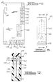
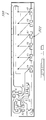
- FIG. 1 and 2 a scroll compressor which incorporates the compressor protection and control subsystem in accordance with the present invention which is designated generally by reference numeral 10. While the compressor protection and control subsystem is being illustrated for exemplary purposes in association with a hermetic scroll compressor, it is within the scope of the present invention to use the compressor protection and control subsystem with other rotary compressors also.
- Compressor 10 comprises a generally cylindrical hermetic shell 12 having welded at the upper end thereof a cap 14 and at the lower end thereof a base 16 having a plurality of mounting feet (not shown) integrally formed therewith.
- Cap 14 is provided with a refrigerant discharge fitting 18 which may have the usual discharge valve therein (not shown).
- Other major elements affixed to the shell include a transversely extending partition 22 which is welded about its periphery at the same point that cap 14 is welded to shell 12, a main bearing housing 24 which is suitably secured to shell 12, a lower bearing housing 26 also having a plurality of radially outwardly extending legs each of which is also suitably secured to shell 12 and an electrical enclosure 28 ( Figure 2).
- a motor stator 30 which is generally square in cross-section but with the corners rounded off is press fitted into shell 12. The flats between the rounded corners on the stator provide passageways between the stator and shell, which facilitate the return flow of lubricant from the top of the shell to the bottom.
- a drive shaft or crankshaft 32 having an eccentric crank pin 34 at the upper end thereof is rotatably journaled in a bearing 36 in main bearing housing 24 and a second bearing 38 in lower bearing housing 26.
- Crankshaft 32 has at the lower end a relatively large diameter concentric bore 40 which communicates with a radially outwardly inclined smaller diameter bore 42 extending upwardly therefrom to the top of crankshaft 32. Disposed within bore 40 is a stirrer 44.
- the lower portion of the interior shell 12 defines an oil sump 46 which is filled with lubricating oil to a level slightly above the lower end of a rotor 48, and bore 40 acts as a pump to pump lubricating fluid up the crankshaft 32 and into passageway 42 and ultimately to all of the various portions of the compressor which require lubrication.
- Crankshaft 32 is rotatively driven by an electric motor including stator 30, windings 50 passing therethrough and rotor 48 press fitted on the crankshaft 32 and having upper and lower counterweights 52 and 54, respectively.
- main bearing housing 24 The upper surface of main bearing housing 24 is provided with a flat thrust bearing surface 56 on which is disposed an orbiting scroll member 58 having the usual spiral vane or wrap 60 on the upper surface thereof.
- orbiting scroll member 58 Projecting downwardly from the lower surface of orbiting scroll member 58 is a cylindrical hub having a journal bearing 62 therein and in which is rotatively disposed a drive bushing 64 having an inner bore 66 in which crank pin 32 is drivingly disposed.
- Crank pin 32 has a flat on one surface which drivingly engages a flat surface (not shown) formed in a portion of bore 66 to provide a radially compliant driving arrangement, such as shown in assignee's U.S. Letters Patent 4,877,382, the disclosure of which is hereby incorporated herein by reference.
- Oldham coupling 68 is also provided positioned between orbiting scroll member 58 and bearing housing 24 and keyed to orbiting scroll member 58 and a non-orbiting scroll member 70 to prevent rotational movement of orbiting scroll member 58.
- Oldham coupling 68 is preferably of the type disclosed in assignee's copending U.S. Letters Patent 5,320,506, the disclosure of which is hereby incorporated herein by reference.
- Non-orbiting scroll member 70 is also provided having a wrap 72 positioned in meshing engagement with wrap 60 of orbiting scroll member 58.
- Non-orbiting scroll member 70 has a centrally disposed discharge passage 74 which communicates with an upwardly open recess 76 which in turn is in fluid communication with a discharge muffler chamber 78 defined by cap 14 and partition 22.
- An annular recess 80 is also formed in non-orbiting scroll member 70 within which is disposed a seal assembly 82.
- Recesses 76 and 80 and seal assembly 82 cooperate to define axial pressure biasing chambers which receive pressurized fluid being compressed by wraps 60 and 72 so as to exert an axial biasing force on non-orbiting scroll member 70 to thereby urge the tips of respective wraps 60, 72 into sealing engagement with the opposed end plate surfaces.
- Seal assembly 82 is preferably of the type described in greater detail in U.S. Patent No. 5,156,539, the disclosure of which is hereby incorporated herein by reference.
- Non-orbiting scroll member 70 is designed to be mounted to bearing housing 24 in a suitable manner such as disclosed in the aforementioned U.S. Patent No. 4,877,382 or U.S. Patent No. 5,102,316, the disclosure of which is hereby incorporated herein by reference.
- electrical enclosure 28 includes an electrical case 84, a compressor protection and control subsystem 86 and a cover 88.
- Electrical case 84 is mounted to shell 12 using a plurality of studs 90 ( Figure 2) which are resistance welded to shell 12.
- Compressor protection and control subsystem 86 is mounted within electrical case 84 using a pair of mounting screws 92.
- Compressor protection and control subsystem 86 is connected to the various components of compressor 10 using wiring which has been omitted from the Figures for purposes of clarity. The connections for compressor protection and control subsystem 86 will be discussed in greater detail below.
- Compressor protection and control subsystem 86 includes a status display 94 which indicates the status of protection and control subsystem 86 and thus the operating status of compressor 10.
- Cover 88 is attached to electrical enclosure 84 using a plurality of screws 98.
- Cover 88 defines an aperture 100 which aligns with status display 94 to enable an individual to determine the operating status of compressor 10 without having to remove cover 88.
- Status display 94 is capable of displaying numbers and some alpha characters to indicate the various fault codes associated with compressor protection and control subsystem 86.
- Compressor protection and control subsystem 86 includes status display 94 as well as terminals 102 through 136 some of which are connected to internally integrated sensors which are in turn connected to a control block 138. Terminals 102 and 104 are connected to a high pressure cut off switch 140 and a low pressure cut off switch 142 through an isolated pressure switch sensing monitor 144. High pressure cut off switch 140 will notify compressor protection and control subsystem 86 of a higher than acceptable pressure reading for compressor 10 and low pressure cut off switch 142 will notify compressor protection and control subsystem 86 of a lower than acceptable pressure reading for compressor 10.
- Terminal 106 is connected to a pressure sensor 146 which monitors the discharge pressure of compressor 10.
- Terminal 108 is connected to a pressure sensor 148 which monitors the suction pressure of compressor 10.
- Terminal 110 is connected to a temperature sensor 150 which monitors the temperature of the discharge gas of compressor 10.
- Terminal 112 is connected to an oil level sensor 152 which monitors the oil level sump 46 of compressor 10. Input from sensors 146-152 are connected to terminals 106-112, respectively, through an analog to digital convertor 154 prior to being input to control block 138.
- Terminals 114, 116, and 118 are connected to a first, a second and a third phase wiring, 156-160, for compressor 10 in order to monitor the status of the three-phase power supply for compressor 10.
- Wirings 156-160 are connected to control block 138 and terminals 114-118 through an isolation and signal conditioner 162.
- Terminals 120 and 122 are connected to a group of motor temperature sensors 164 through a PTC Input circuit 166.
- Terminal 124 is connected to a compressor control system 168 which indicates that all monitored systems are acceptable and compressor 10 is free to operate.
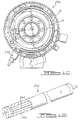
- Vibration detection can be added to compressor protection and control subsystem 86 by incorporating a preferred vibration sensor 180 within compressor protection and control subsystem 86 as shown in dashed lines in Figure 4.
- Vibration sensor 180 is shown in Figures 6 and 7 and it comprises a cover 182, a contractor ring 184, a terminal rod 186, a spring wire 188, a ball 190, and an end cap 192.
- Cover 182 is a generally rectangular shaped plastic component defining a internal circular bore 194.
- Contractor ring 184 is fit within an enlarged portion of bore 194 and rests against a shoulder 196 formed by bore 194.
- Terminal rod 186 extends through a side wall of cover 182.
- Terminal rod 186 is welded to contractor ring 184 such that the end of terminal rod 186 extending through cover 182 can be utilized as a solder point for vibration sensor 180.
- Spring wire 188 is an L-shaped wire member which has one end of the L extending through the side wall of cover 182 and the opposite end of the L extending axially down the center line of circular bore 194 such that the end of spring wire 188 terminates in approximately the center of contractor ring 184.
- Ball 190 includes a radially extending bore 198 which extends from the outer surface of ball 190 to approximately the center of ball 190.
- ball 190 and spring wire 188 are assembled by inserting spring wire 188 into bore 198 and applying a strong permanent epoxy or by other methods known well in the art.
- the end of spring wire 188 which extends out of cover 182 is used as a solder point for vibration sensor 180.
- End cap 192 is attached to cover 182 by use of a permanent set epoxy which seals bore 194 and thus protects the electrical contacts of vibration sensor 180.
- spring wire 188 is made from spring quality steel or music wire
- ball 190 is made form stainless steel (either 302 or 304)
- contractor ring 184 is made from a seamless 304 stainless steel hollow tubular stock.
- Contractor ring 184 and ball 190 are preferably plated with gold up to a thickness of 0.000015 inches to prevent oxidation.
- spring wire 188 and contractor ring 184 are molded in place.
- Ball 190 is then secure to spring wire 188 and then end cap 192 is assembled.
- Ball 190 and spring wire 188 comprise a simple spring-mass system.
- Spring wire 188 has the dual purpose of serving as one electrical terminal and also to act as the stiffness member of the spring-mass system.
- Vibration sensor 180 is located on the circuit board for compressor protection and control subsystem 86 and is most sensitive to vibration in the plane which is perpendicular to the long axis of vibration sensor 180 or the long axis of spring wire 188.
- Sensor 180 is actually a form of electrical switch which requires a minimum displacement before the momentary circuit closures or pulses begin to appear.
- a sensor input network block includes an RC filter which reduces the noise content of the signal.
- the response of vibration sensor 180 is governed by the stiffness of spring wire 188 and the mass of ball 190.
- System response is measured in terms of the amplitude of oscillations of ball 190 when vibration sensor 180 is attached to compressor 10.
- sensor 180 is designed to have a natural frequency close to the operating frequency of compressor 10.
- the natural frequency of sensor 180 is maintained on the higher side of the operating frequency of compressor 10 to eliminate nuisance trips.
- the stiffness of spring wire 188 is a function of the diameter, length and material of spring wire 188, the mass of ball 190 is a function of its material and its diameter.
- the sensitivity of sensor 180 is determined by the gap between ball 190 and contact ring 184 and how close the natural frequency of sensor 180 is to the operating frequency of compressor 10. If the two frequencies are close, the system may be over sensitive; i.e. a small change in input vibration amplitude will result in a significant change in output vibration of movement of ball 190. Similarly, if the two frequencies are far apart, the system may be under sensitive and require a larger input vibration amplitude to cause a small change in output vibration or movement of ball 190.
- Computer studies and parallel experimental work has determined that a preferred sensor 180 will trigger at input signal levels of 10-15 mils of input vibration. This preferred design is insensitive to input vibration under 8 mils.
- Compressor protection and control subsystem module 86 preferably includes a first counter which continuously counts any pulses or triggering that are present using a 10 second time interval. If the number of pulses counted during any 10 second interval exceeds a predetermined number, a limit condition flag is turned on. Conversely, if the number of pulses counted during any 10 second interval is less than a predetermined number, the limit condition flag is turned off. Compressor protection and control subsystem 86 implements a second counter which is an up-down counter. It is clocked by an internal 1 second clock.
- the counter is limited to 0 counts in the down direction and 120 counts in the up direction. If the condition limit flag is turned on, the counter counts up. If the limit condition flag is turned off, the counter counts down. If at any time the count reaches 120, control and protection module 86 turns off the control relay and sets status display 94 to indicate a "vibration trip condition". Recycling of power to compressor protection and control subsystem 86 is required to clear this condition and reset the counter to 0.
- Control block 138 of compressor protection and control subsystem 86 can also be used to control other various and perhaps optional systems incorporated into compressor 10.
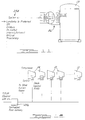
- Terminal 126 is designed to be connected to a solenoid control system 210 which in turn is connected to an unloading control for a compressor for controlling the capacity of a compressor 214 shown in Figure 8.
- Compressor 214 is identical to compressor 10 except for the incorporation of a capacity control system 216 which is controlled by control block 138.
- Terminal 128 is designed to be connected to a solenoid control system 218 which is, in turn, connected to a liquid injection system 222 for controlling the liquid injection for a compressor 224 shown in Figure 9.
- Compressor 224 is identical to compressor 10 except for the incorporation of liquid injection system 222.
- Terminal 130 is designed to be connected to a solenoid control system 226 which is, in turn, connected to an oil injection system 230 for controlling oil injection for a compressor 234 shown in Figure 10.
- Compressor 234 is identical to compressor 10 except for the incorporation of oil injection system 230.
- Terminal 132 is designed to be connected to a heater control system 236 which is, in turn, connected to a crankcase heater 238 for heating the lubricating oil in sump 46 of compressor 10 as shown in Figure 1.
- Figures 8-10 each show a separate system added to compressor 10, it is within the scope of the present invention to include one or more of systems 216, 222 or 230 if desired.
- Gateway 250 uses Motorola's Serial Peripheral Interface (SPI) for communicating with bridge or gateway modules. Motorola's SPI was designed to allow communications between a microcontroller and integrated circuits on a board providing expanded peripheral functions. Another bus, the I 2 C is similar to the SPI and was developed by Signetics/Philips Semiconductor. By using one of these buses, the only hardware required for connection to a pluggable gateway board is a suitable connector. By taking this approach, the system communications protocol is limited only by the gateways made available.
- SPI Serial Peripheral Interface
- the SPI and I 2 C are the lowest cost approaches to providing communications and all that is needed is an adapter or a gateway.
- the preferred embodiment uses a serial interface using RS-485.
- the protocol used by the advanced compressor control and protection system of the present invention for either the simple SPI-to-gateway communications or in the case of an RS-485 based local network application is a master-slave protocol.
- the system control is the master when the local RS-485 interface is used. If another protocol is required, the gateway module acts as the master on the compressor control interface side.
- Node Address is contained in the five most significant bits of Byte 0.
- the message type is contained in the least significant three bits of Byte 0. Eight message types are defined as follows:
- a message type may have up to 8 packets. Each packet may be 1 to 32 bytes in length and is sent in a separate message. The first message sent has the packet number set to the number of packets to be sent. Each subsequent message has the packet number decremented. The last message contains the last packet to be sent and is packet number zero (0).
- the packet Number is contained in the most significant 3 bits of Byte 1.
- the Packet Length specifies the length of the Data Packet in each message.
- the Packet Length is contained in the least significant 5 bits of Byte 1.
- Each message contains a data packet with up to 31 data bytes. The only exception is a packet length of zero (0) bytes. In this case there is no data packet in the message.
- Node definitions can be created for any component in a system that is capable of supporting communications.
- a good example would be a refrigeration case control.
- node definitions for individual or groups of sensors and actuators would make sense. These definitions would define the specific messages and their content as required for the particular devices. This document release focuses on the compressor node only.
- the compressor node utilizes all message types available.
- the Configuration data message type 5 is used to transfer the compressor configuration data between the system master and each compressor node.
- the compressor is shipped with the data preconfigured.
- the system master may send a Configuration Request to a selected compressor node and get an image of the stored data. It may modify that data or it may construct a completely new image and send it to the compressor for storage by sending it in the appropriate series of Configuration Data packets.
- Typical configuration variables are listed below.
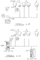
- compressor 10 is illustrated showing the Serial Peripheral Interface (SPI) for connecting compressor protection and control subsystem 86 of compressor 10 to a central control system 254.
- SPI Serial Peripheral Interface
- subsystem 86 of compressor 10 can be controlled by and communicate with a master network.
- the connection and communication with the master network is preferably through LonWorks but other network connections such as SPi, CANBus, Device Net, Internet/Intranet, BAC net or a Proprietary connection can be established.
- Figure 12 illustrates the network system when a centralized rack gateway 256 is utilized to communicate with a group of compressors 10
- Figure 13 illustrates the network system when a rack/system control 258 acts as the gateway for communicating with a group of compressors 10
- Figure 14 illustrates the network system when an Internet web server 260 or a local Intranet server 262 is utilized to communicate with individual Ethernet gateways associated with each compressor 10.
- a capacitance based sensor 300 shown in Figure 15 is one option for an oil sensor. There is a large enough dielectric constant of oil versus refrigerant gas to be able to derive a usable signal. The volume construction of such a device having a consistent capacitance from unit to unit without calibration is feasible if the electrodes are arranged coaxially. Sensor 300 is comprised of a hollow stainless tube 302 with a small coaxially positioned rod 304.
- thermocouple liquid level sensor 320 is shown in Figure 16.
- Sensor 320 comprises an unevenly heated thermocouple array 322.
- Sensor 320 requires a compensation for the effect of different gas densities by using a separate unevenly heated thermocouple pair which is always disposed within the suction gas of the compressor.
- a mathematical model was developed using the output from the thermocouple disposed in the gas to correct the output of the thermocouple disposed in the lubricant for variation pressure and temperature of the suction gas over the compressor's operating envelope.
- FIG. 17 a system schematic for a compressor protection and control subsystem 86' for use with a semi-hermetic rotary compressor is disclosed.
- Subsystem 86' shown in Figure 17, is similar to subsystem 86 shown in Figure 5 except for the addition of control for an oil switch 300.
- a semi-hermetic rotary compressor is similar to a hermetic rotary compressor except that the shell for the semi-hermetic rotary compressor is bolted together rather than being welded as shown for shell 12.
- the semi-hermetic rotary compressor is typically equipped with a positive displacement lubricant pump which maintains an oil pressure within the lubrication system for the semi-hermetic rotary compressor.
- a pressure sensor monitors the pressure for the lubrication system with the pressure sensor communicating with control block 138 through a pair of terminals 302 and 304.
- Logic within control block 138 monitors the lubrication after lubrication pressure is determined to be low or inadequate for a specified period of time. The time delay used for controlling the compressor for a lack of sufficient oil pressure avoids problems associated with mis-trips caused to varying oil pressure.
- the function and operation of the remainder of compressor protection and control subsystem 86' is the same as that described above for compressor protection and control subsystem 86.
Priority Applications (1)
| Application Number | Priority Date | Filing Date | Title |
|---|---|---|---|
| EP04022784.5A EP1500821B1 (fr) | 2000-02-29 | 2001-02-26 | Compresseur avec un système de contrôle et de protection |
Applications Claiming Priority (2)
| Application Number | Priority Date | Filing Date | Title |
|---|---|---|---|
| US515802 | 2000-02-29 | ||
| US09/515,802 US6302654B1 (en) | 2000-02-29 | 2000-02-29 | Compressor with control and protection system |
Related Child Applications (1)
| Application Number | Title | Priority Date | Filing Date |
|---|---|---|---|
| EP04022784.5A Division EP1500821B1 (fr) | 2000-02-29 | 2001-02-26 | Compresseur avec un système de contrôle et de protection |
Publications (3)
| Publication Number | Publication Date |
|---|---|
| EP1138949A2 true EP1138949A2 (fr) | 2001-10-04 |
| EP1138949A3 EP1138949A3 (fr) | 2002-06-05 |
| EP1138949B1 EP1138949B1 (fr) | 2005-04-27 |
Family
ID=24052795
Family Applications (2)
| Application Number | Title | Priority Date | Filing Date |
|---|---|---|---|
| EP04022784.5A Expired - Lifetime EP1500821B1 (fr) | 2000-02-29 | 2001-02-26 | Compresseur avec un système de contrôle et de protection |
| EP01301752A Expired - Lifetime EP1138949B1 (fr) | 2000-02-29 | 2001-02-26 | Compresseur avec système de protection et de réglage |
Family Applications Before (1)
| Application Number | Title | Priority Date | Filing Date |
|---|---|---|---|
| EP04022784.5A Expired - Lifetime EP1500821B1 (fr) | 2000-02-29 | 2001-02-26 | Compresseur avec un système de contrôle et de protection |
Country Status (8)
| Country | Link |
|---|---|
| US (6) | US6302654B1 (fr) |
| EP (2) | EP1500821B1 (fr) |
| KR (2) | KR20010085695A (fr) |
| CN (2) | CN1632317B (fr) |
| AU (5) | AU782338B2 (fr) |
| BR (1) | BR0100912B1 (fr) |
| DE (1) | DE60110300T8 (fr) |
| TW (1) | TW546442B (fr) |
Cited By (28)
| Publication number | Priority date | Publication date | Assignee | Title |
|---|---|---|---|---|
| EP1219836A2 (fr) * | 2000-12-20 | 2002-07-03 | Carrier Corporation | Compresseur avec regulation de la pression de sortie |
| WO2005022049A2 (fr) * | 2003-08-25 | 2005-03-10 | Computer Process Controls, Inc. | Systeme de commande de refrigeration |
| EP1577559A1 (fr) * | 2004-03-15 | 2005-09-21 | VARIAN S.p.A. | Dispositif de pompage à vide |
| GB2413365A (en) * | 2004-04-19 | 2005-10-26 | Scroll Tech | Compressor assembly with receiver and memory unit |
| WO2009091901A1 (fr) * | 2008-01-17 | 2009-07-23 | Bitzer Scroll Inc. | Compresseur à spirale ayant une bande d'alimentation standardisée |
| US7647201B2 (en) | 2005-04-26 | 2010-01-12 | Emerson Climate Technologies, Inc. | Compressor information network and method |
| WO2010144596A3 (fr) * | 2009-06-11 | 2011-01-27 | Illinois Tool Works Inc. | Prévention du blocage par congélation d'un compresseur par temps froid |
| US8065886B2 (en) | 2001-05-03 | 2011-11-29 | Emerson Retail Services, Inc. | Refrigeration system energy monitoring and diagnostics |
| US8473106B2 (en) | 2009-05-29 | 2013-06-25 | Emerson Climate Technologies Retail Solutions, Inc. | System and method for monitoring and evaluating equipment operating parameter modifications |
| US8495886B2 (en) | 2001-05-03 | 2013-07-30 | Emerson Climate Technologies Retail Solutions, Inc. | Model-based alarming |
| US8700444B2 (en) | 2002-10-31 | 2014-04-15 | Emerson Retail Services Inc. | System for monitoring optimal equipment operating parameters |
| US8964338B2 (en) | 2012-01-11 | 2015-02-24 | Emerson Climate Technologies, Inc. | System and method for compressor motor protection |
| US8974573B2 (en) | 2004-08-11 | 2015-03-10 | Emerson Climate Technologies, Inc. | Method and apparatus for monitoring a refrigeration-cycle system |
| US9121407B2 (en) | 2004-04-27 | 2015-09-01 | Emerson Climate Technologies, Inc. | Compressor diagnostic and protection system and method |
| US9140728B2 (en) | 2007-11-02 | 2015-09-22 | Emerson Climate Technologies, Inc. | Compressor sensor module |
| US9285802B2 (en) | 2011-02-28 | 2016-03-15 | Emerson Electric Co. | Residential solutions HVAC monitoring and diagnosis |
| US9310439B2 (en) | 2012-09-25 | 2016-04-12 | Emerson Climate Technologies, Inc. | Compressor having a control and diagnostic module |
| US9310094B2 (en) | 2007-07-30 | 2016-04-12 | Emerson Climate Technologies, Inc. | Portable method and apparatus for monitoring refrigerant-cycle systems |
| US9480177B2 (en) | 2012-07-27 | 2016-10-25 | Emerson Climate Technologies, Inc. | Compressor protection module |
| US9551504B2 (en) | 2013-03-15 | 2017-01-24 | Emerson Electric Co. | HVAC system remote monitoring and diagnosis |
| US9638436B2 (en) | 2013-03-15 | 2017-05-02 | Emerson Electric Co. | HVAC system remote monitoring and diagnosis |
| US9765979B2 (en) | 2013-04-05 | 2017-09-19 | Emerson Climate Technologies, Inc. | Heat-pump system with refrigerant charge diagnostics |
| US9803902B2 (en) | 2013-03-15 | 2017-10-31 | Emerson Climate Technologies, Inc. | System for refrigerant charge verification using two condenser coil temperatures |
| US9823632B2 (en) | 2006-09-07 | 2017-11-21 | Emerson Climate Technologies, Inc. | Compressor data module |
| US9885507B2 (en) | 2006-07-19 | 2018-02-06 | Emerson Climate Technologies, Inc. | Protection and diagnostic module for a refrigeration system |
| US10041713B1 (en) | 1999-08-20 | 2018-08-07 | Hudson Technologies, Inc. | Method and apparatus for measuring and improving efficiency in refrigeration systems |
| US10144083B2 (en) | 2013-02-22 | 2018-12-04 | Illinois Tool Works Inc. | Multi-operator engine driven welder system |
| EP3597915B1 (fr) | 2018-07-20 | 2021-03-10 | Emerson Climate Technologies GmbH | Protection de compresseur de réfrigération |
Families Citing this family (84)
| Publication number | Priority date | Publication date | Assignee | Title |
|---|---|---|---|---|
| US6302654B1 (en) * | 2000-02-29 | 2001-10-16 | Copeland Corporation | Compressor with control and protection system |
| US6999996B2 (en) * | 2000-03-14 | 2006-02-14 | Hussmann Corporation | Communication network and method of communicating data on the same |
| US7047753B2 (en) * | 2000-03-14 | 2006-05-23 | Hussmann Corporation | Refrigeration system and method of operating the same |
| US6332327B1 (en) | 2000-03-14 | 2001-12-25 | Hussmann Corporation | Distributed intelligence control for commercial refrigeration |
| US6647735B2 (en) * | 2000-03-14 | 2003-11-18 | Hussmann Corporation | Distributed intelligence control for commercial refrigeration |
| US6973794B2 (en) * | 2000-03-14 | 2005-12-13 | Hussmann Corporation | Refrigeration system and method of operating the same |
| US6406265B1 (en) * | 2000-04-21 | 2002-06-18 | Scroll Technologies | Compressor diagnostic and recording system |
| US6485268B1 (en) * | 2000-10-17 | 2002-11-26 | Scroll Technologies | Oil utilized as motor protector trip for scroll compressor |
| US6848889B2 (en) * | 2000-10-17 | 2005-02-01 | Scroll Technologies | Oil utilized as motor protector trip for scroll compressor |
| JP4578729B2 (ja) * | 2001-07-06 | 2010-11-10 | 株式会社日本自動車部品総合研究所 | 油分率測定装置およびこれを用いた冷凍装置 |
| US6550260B1 (en) * | 2001-09-28 | 2003-04-22 | Carrier Corporation | Vibration detection in a transport refrigeration system through current sensing |
| US20030077179A1 (en) * | 2001-10-19 | 2003-04-24 | Michael Collins | Compressor protection module and system and method incorporating same |
| US8463441B2 (en) | 2002-12-09 | 2013-06-11 | Hudson Technologies, Inc. | Method and apparatus for optimizing refrigeration systems |
| US7059839B2 (en) * | 2002-12-10 | 2006-06-13 | Tecumseh Products Company | Horizontal compressor end cap with a terminal, a visually transparent member, and a heater well mounted on the end cap projection |
| US6886354B2 (en) * | 2003-04-04 | 2005-05-03 | Carrier Corporation | Compressor protection from liquid hazards |
| US6925823B2 (en) * | 2003-10-28 | 2005-08-09 | Carrier Corporation | Refrigerant cycle with operating range extension |
| EP1700067B1 (fr) * | 2003-12-30 | 2014-07-30 | Emerson Climate Technologies, Inc. | Systeme de diagnostic et de protection de compresseur |
| US7194871B2 (en) * | 2004-04-20 | 2007-03-27 | Danfoss Commercial Compressors | Electrical and electronic component cabinet for a refrigeration compressor |
| JP2006037724A (ja) * | 2004-07-22 | 2006-02-09 | Matsushita Electric Ind Co Ltd | 密閉型電動圧縮機 |
| US7316541B2 (en) * | 2004-08-19 | 2008-01-08 | Black & Decker Inc. | Engine-powered air compressor with a controller for low oil condition |
| GB0424734D0 (en) * | 2004-11-09 | 2004-12-08 | Boc Group Plc | Vacuum pumping system |
| KR20060046987A (ko) * | 2004-11-12 | 2006-05-18 | 삼성전자주식회사 | 용량가변형 에어컨의 압축기 오결선 검지장치 및 그 방법 |
| US7418521B2 (en) * | 2004-12-07 | 2008-08-26 | Alliance Laundry Systems Llc | Controller for bridging a host computer and networked laundry machines |
| US7712319B2 (en) * | 2004-12-27 | 2010-05-11 | Carrier Corporation | Refrigerant charge adequacy gauge |
| US20060138772A1 (en) * | 2004-12-27 | 2006-06-29 | Carrier Corporation | Braze-free connector |
| US20060137369A1 (en) * | 2004-12-27 | 2006-06-29 | Carrier Corporation | Single sensor three-step refrigerant charge indicator |
| US7610765B2 (en) * | 2004-12-27 | 2009-11-03 | Carrier Corporation | Refrigerant charge status indication method and device |
| US20060138771A1 (en) * | 2004-12-27 | 2006-06-29 | Carrier Corporation | Braze-free connector for joining a pair of flow lines |
| US7552596B2 (en) * | 2004-12-27 | 2009-06-30 | Carrier Corporation | Dual thermochromic liquid crystal temperature sensing for refrigerant charge indication |
| US7472557B2 (en) * | 2004-12-27 | 2009-01-06 | Carrier Corporation | Automatic refrigerant charging apparatus |
| US20060143348A1 (en) * | 2004-12-29 | 2006-06-29 | Wilson Matthew T | System, method, and apparatus for extended serial peripheral interface |
| EP1851959B1 (fr) | 2005-02-21 | 2012-04-11 | Computer Process Controls, Inc. | Systeme de surveillance et de commande d'entreprise |
| JP2006307855A (ja) * | 2005-04-26 | 2006-11-09 | Copeland Corp | 圧縮機メモリシステム、圧縮機情報ネットワークおよび保証管理方法 |
| US7419192B2 (en) * | 2005-07-13 | 2008-09-02 | Carrier Corporation | Braze-free connector utilizing a sealant coated ferrule |
| US7533106B2 (en) * | 2005-09-09 | 2009-05-12 | Quickfilter Technologies, Inc. | Data structures and circuit for multi-channel data transfers using a serial peripheral interface |
| US7752853B2 (en) | 2005-10-21 | 2010-07-13 | Emerson Retail Services, Inc. | Monitoring refrigerant in a refrigeration system |
| US7752854B2 (en) | 2005-10-21 | 2010-07-13 | Emerson Retail Services, Inc. | Monitoring a condenser in a refrigeration system |
| US7665315B2 (en) | 2005-10-21 | 2010-02-23 | Emerson Retail Services, Inc. | Proofing a refrigeration system operating state |
| US20070101737A1 (en) * | 2005-11-09 | 2007-05-10 | Masao Akei | Refrigeration system including thermoelectric heat recovery and actuation |
| US8287245B2 (en) * | 2006-07-06 | 2012-10-16 | Bristol Compressors International, Inc. | System and method for control of devices internal to a hermetic compressor |
| JP4165581B2 (ja) * | 2006-07-11 | 2008-10-15 | ダイキン工業株式会社 | 空気調和装置の伝送装置 |
| GB2443421B (en) * | 2006-08-30 | 2009-02-18 | Compair Uk Ltd | Improvements in compressors units |
| AU2013202431B2 (en) * | 2006-09-07 | 2015-05-07 | Emerson Climate Technologies, Inc. | Compressor data module |
| US9568226B2 (en) * | 2006-12-20 | 2017-02-14 | Carrier Corporation | Refrigerant charge indication |
| US8290722B2 (en) * | 2006-12-20 | 2012-10-16 | Carrier Corporation | Method for determining refrigerant charge |
| US8393169B2 (en) | 2007-09-19 | 2013-03-12 | Emerson Climate Technologies, Inc. | Refrigeration monitoring system and method |
| US7895003B2 (en) * | 2007-10-05 | 2011-02-22 | Emerson Climate Technologies, Inc. | Vibration protection in a variable speed compressor |
| US8459053B2 (en) | 2007-10-08 | 2013-06-11 | Emerson Climate Technologies, Inc. | Variable speed compressor protection system and method |
| US8160827B2 (en) | 2007-11-02 | 2012-04-17 | Emerson Climate Technologies, Inc. | Compressor sensor module |
| DE102008011454A1 (de) * | 2008-02-27 | 2009-09-17 | Robert Bosch Gmbh | Kompressionswärmepumpe und Verfahren zu ihrem Betreiben |
| JP5203754B2 (ja) * | 2008-03-11 | 2013-06-05 | 株式会社日立産機システム | インバータ圧縮機の制御方法及びインバータ圧縮機 |
| DE102008025327B4 (de) * | 2008-05-27 | 2010-09-09 | Danfoss A/S | Kältemittelverdichter |
| JP5192440B2 (ja) * | 2009-05-15 | 2013-05-08 | 株式会社神戸製鋼所 | モータ及びこれを備えた圧縮機 |
| CN102022324A (zh) * | 2009-09-18 | 2011-04-20 | 乐金电子(天津)电器有限公司 | 旋转式压缩机 |
| US8734125B2 (en) | 2009-09-24 | 2014-05-27 | Emerson Climate Technologies, Inc. | Crankcase heater systems and methods for variable speed compressors |
| KR101452767B1 (ko) * | 2010-04-01 | 2014-10-21 | 엘지전자 주식회사 | 압축기의 오일 레벨 감지수단 |
| US8807959B2 (en) * | 2010-11-30 | 2014-08-19 | General Electric Company | Reciprocating compressor and methods for monitoring operation of same |
| EP2589898B1 (fr) | 2011-11-04 | 2018-01-24 | Emerson Climate Technologies GmbH | Système de gestion de l'huile pour compresseur |
| US9759465B2 (en) | 2011-12-27 | 2017-09-12 | Carrier Corporation | Air conditioner self-charging and charge monitoring system |
| CN103256225A (zh) * | 2012-02-16 | 2013-08-21 | 广东美芝制冷设备有限公司 | 旋转式压缩机的冷却结构 |
| DE102012102405A1 (de) * | 2012-03-21 | 2013-09-26 | Bitzer Kühlmaschinenbau Gmbh | Kältemittelverdichter |
| US9188124B2 (en) | 2012-04-30 | 2015-11-17 | Emerson Climate Technologies, Inc. | Scroll compressor with unloader assembly |
| US8931288B2 (en) * | 2012-10-19 | 2015-01-13 | Lennox Industries Inc. | Pressure regulation of an air conditioner |
| US9181939B2 (en) | 2012-11-16 | 2015-11-10 | Emerson Climate Technologies, Inc. | Compressor crankcase heating control systems and methods |
| US9115718B2 (en) | 2013-01-22 | 2015-08-25 | Emerson Climate Technologies, Inc. | Compressor bearing and unloader assembly |
| CN107178500B (zh) * | 2013-01-22 | 2019-06-18 | 艾默生环境优化技术有限公司 | 压缩机 |
| MX359528B (es) * | 2013-02-18 | 2018-10-01 | Joy Global Surface Mining Inc | Sistemas y métodos para monitorear un sistema de fluido de una máquina de minería. |
| WO2014153213A1 (fr) | 2013-03-14 | 2014-09-25 | Harnischfeger Technologies, Inc. | Système et procédé permettant de contrôler l'arbre de frein d'une machine d'exploitation minière |
| CN104074726B (zh) * | 2013-03-29 | 2016-08-17 | 艾默生环境优化技术(苏州)有限公司 | 压缩机系统及其控制方法 |
| US9353738B2 (en) | 2013-09-19 | 2016-05-31 | Emerson Climate Technologies, Inc. | Compressor crankcase heating control systems and methods |
| EP2853742B1 (fr) * | 2013-09-27 | 2016-04-20 | Emerson Climate Technologies GmbH | Procédé et appareil de détection d'huile dans un compresseur |
| US10215175B2 (en) | 2015-08-04 | 2019-02-26 | Emerson Climate Technologies, Inc. | Compressor high-side axial seal and seal assembly retainer |
| DE102016103426B4 (de) * | 2016-02-26 | 2020-06-18 | Kriwan Industrie-Elektronik Gmbh | Kältemittelverdichter und Verfahren zur Überwachung, Regelung und/oder Steuerung eines Kältemittelverdichters |
| US10829226B2 (en) | 2016-05-24 | 2020-11-10 | Textron Innovations, Inc. | Compressor temperature control system and method |
| US10650621B1 (en) | 2016-09-13 | 2020-05-12 | Iocurrents, Inc. | Interfacing with a vehicular controller area network |
| US11015598B2 (en) | 2018-04-11 | 2021-05-25 | Emerson Climate Technologies, Inc. | Compressor having bushing |
| US11002276B2 (en) | 2018-05-11 | 2021-05-11 | Emerson Climate Technologies, Inc. | Compressor having bushing |
| DE102018126553A1 (de) * | 2018-10-24 | 2020-04-30 | Dürr Dental SE | Sensoreneinheit und Druckluftkompressorsystem mit einer solchen |
| TWM578426U (zh) * | 2019-01-16 | 2019-05-21 | 達佛羅企業有限公司 | Tool machine oil control system |
| US11206743B2 (en) | 2019-07-25 | 2021-12-21 | Emerson Climate Technolgies, Inc. | Electronics enclosure with heat-transfer element |
| CN113285568A (zh) * | 2020-01-31 | 2021-08-20 | 翰昂汽车零部件有限公司 | 电动压缩机及电动压缩机的制造信息管理方法 |
| CN112229085B (zh) * | 2020-09-30 | 2021-07-09 | 西安交通大学 | 一种适用于大温跨的低温热泵循环系统及循环方法 |
| CN114688031A (zh) * | 2020-12-29 | 2022-07-01 | 丹佛斯(天津)有限公司 | 压缩机和控制该压缩机的方法 |
| CN115788887B (zh) * | 2022-11-28 | 2023-07-21 | 山东海福德机械有限公司 | 基于数据分析的罗茨鼓风机运行工况监管预警系统 |
Citations (5)
| Publication number | Priority date | Publication date | Assignee | Title |
|---|---|---|---|---|
| US4877382A (en) | 1986-08-22 | 1989-10-31 | Copeland Corporation | Scroll-type machine with axially compliant mounting |
| US5102316A (en) | 1986-08-22 | 1992-04-07 | Copeland Corporation | Non-orbiting scroll mounting arrangements for a scroll machine |
| US5156539A (en) | 1990-10-01 | 1992-10-20 | Copeland Corporation | Scroll machine with floating seal |
| US5320506A (en) | 1990-10-01 | 1994-06-14 | Copeland Corporation | Oldham coupling for scroll compressor |
| US5975854A (en) | 1997-05-09 | 1999-11-02 | Copeland Corporation | Compressor with protection module |
Family Cites Families (83)
| Publication number | Priority date | Publication date | Assignee | Title |
|---|---|---|---|---|
| DE1403467A1 (de) * | 1961-06-29 | 1969-10-09 | Vogtlandgruben Lengenfeld Veb | Steuerungs- und UEberwachungs-Einrichtung fuer ein- und mehrstufige Kolben-,Rotations- und Turboverdichter |
| US3735377A (en) | 1971-03-19 | 1973-05-22 | Phillips Petroleum Co | Monitoring and shutdown apparatus |
| DE2203047C3 (de) | 1972-01-22 | 1978-12-14 | Maschf Augsburg Nuernberg Ag | Vorrichtung zur Überwachung der Laufgüte eines Kolbens einer Hubkolbenmaschine |
| US4066869A (en) * | 1974-12-06 | 1978-01-03 | Carrier Corporation | Compressor lubricating oil heater control |
| US4060716A (en) | 1975-05-19 | 1977-11-29 | Rockwell International Corporation | Method and apparatus for automatic abnormal events monitor in operating plants |
| US4102394A (en) | 1977-06-10 | 1978-07-25 | Energy 76, Inc. | Control unit for oil wells |
| SE427861B (sv) | 1979-10-29 | 1983-05-09 | Saab Scania Ab | Forfarande for att undvika onormala forbrenningar i en forbrenningsmotor samt arrangemang for utovande av forfarandet |
| US4502843A (en) * | 1980-03-31 | 1985-03-05 | Noodle Corporation | Valveless free plunger and system for well pumping |
| US4345162A (en) * | 1980-06-30 | 1982-08-17 | Honeywell Inc. | Method and apparatus for power load shedding |
| US4390321A (en) | 1980-10-14 | 1983-06-28 | American Davidson, Inc. | Control apparatus and method for an oil-well pump assembly |
| US4425010A (en) | 1980-11-12 | 1984-01-10 | Reliance Electric Company | Fail safe dynamoelectric machine bearing |
| DE3048340C2 (de) * | 1980-12-20 | 1982-12-09 | Uni-Cardan Ag, 5200 Siegburg | Winkelbewegliche Gelenkkupplung |
| US4399548A (en) | 1981-04-13 | 1983-08-16 | Castleberry Kimberly N | Compressor surge counter |
| JPS58108361A (ja) * | 1981-12-21 | 1983-06-28 | サンデン株式会社 | 車輌用空調装置の制御装置 |
| US4390922A (en) | 1982-02-04 | 1983-06-28 | Pelliccia Raymond A | Vibration sensor and electrical power shut off device |
| US4479389A (en) | 1982-02-18 | 1984-10-30 | Allied Corporation | Tuned vibration detector |
| US4429578A (en) | 1982-03-22 | 1984-02-07 | General Electric Company | Acoustical defect detection system |
| US4444017A (en) * | 1982-03-29 | 1984-04-24 | Carrier Corporation | Method and apparatus for controlling the operation of a compressor crankcase heater |
| US4467230A (en) * | 1982-11-04 | 1984-08-21 | Rovinsky Robert S | Alternating current motor speed control |
| US4502842A (en) * | 1983-02-02 | 1985-03-05 | Colt Industries Operating Corp. | Multiple compressor controller and method |
| JPS60147585A (ja) * | 1984-01-11 | 1985-08-03 | Hitachi Ltd | 圧縮機の制御方法 |
| DE3420144A1 (de) * | 1984-05-30 | 1985-12-05 | Loewe Pumpenfabrik GmbH, 2120 Lüneburg | Regelungs- und steuerungssystem, insbes. fuer wassering-vakuumpumpen |
| CA1239951A (fr) * | 1987-03-30 | 1988-08-02 | John T. Ross | "guidon touring" et "adaptateur des manettes de freins" |
| DE3725754A1 (de) | 1987-08-04 | 1989-02-16 | Busch Dieter & Co Prueftech | Einrichtung zum ueberwachen von pumpen auf gefaehrdung durch kavitation |
| US4829779A (en) * | 1987-12-15 | 1989-05-16 | Hussmann Corporation | Interface adapter for interfacing a remote controller with commercial refrigeration and environmental control systems |
| US4913625A (en) | 1987-12-18 | 1990-04-03 | Westinghouse Electric Corp. | Automatic pump protection system |
| US4884412A (en) | 1988-09-15 | 1989-12-05 | William Sellers | Compressor slugging protection device and method therefor |
| JPH02110242A (ja) * | 1988-10-18 | 1990-04-23 | Mitsubishi Heavy Ind Ltd | 空気調和機用遠隔故障診断装置 |
| JPH0765574B2 (ja) * | 1989-05-09 | 1995-07-19 | ダイキン工業株式会社 | スクロール形圧縮機を用いた冷凍装置 |
| US4975024A (en) * | 1989-05-15 | 1990-12-04 | Elliott Turbomachinery Co., Inc. | Compressor control system to improve turndown and reduce incidents of surging |
| US5119466A (en) * | 1989-05-24 | 1992-06-02 | Asmo Co., Ltd. | Control motor integrated with a direct current motor and a speed control circuit |
| US5073091A (en) * | 1989-09-25 | 1991-12-17 | Vickers, Incorporated | Power transmission |
| US5056036A (en) | 1989-10-20 | 1991-10-08 | Pulsafeeder, Inc. | Computer controlled metering pump |
| US5109700A (en) | 1990-07-13 | 1992-05-05 | Life Systems, Inc. | Method and apparatus for analyzing rotating machines |
| US5141407A (en) * | 1990-10-01 | 1992-08-25 | Copeland Corporation | Scroll machine with overheating protection |
| US5203178A (en) | 1990-10-30 | 1993-04-20 | Norm Pacific Automation Corp. | Noise control of air conditioner |
| US5259210A (en) * | 1991-01-10 | 1993-11-09 | Sanyo Electric Co., Ltd. | Refrigerating apparatus and method of controlling refrigerating apparatus in accordance with fuzzy reasoning |
| US5167491A (en) * | 1991-09-23 | 1992-12-01 | Carrier Corporation | High to low side bypass to prevent reverse rotation |
| US5209076A (en) * | 1992-06-05 | 1993-05-11 | Izon, Inc. | Control system for preventing compressor damage in a refrigeration system |
| US5509786A (en) | 1992-07-01 | 1996-04-23 | Ubukata Industries Co., Ltd. | Thermal protector mounting structure for hermetic refrigeration compressors |
| JPH0658273A (ja) * | 1992-08-03 | 1994-03-01 | Daikin Ind Ltd | 横形スクロール圧縮機 |
| US5224835A (en) | 1992-09-02 | 1993-07-06 | Viking Pump, Inc. | Shaft bearing wear detector |
| US5493867A (en) * | 1992-11-18 | 1996-02-27 | Whirlpool Corporation | Fuzzy logic adaptive defrost control |
| US5381692A (en) | 1992-12-09 | 1995-01-17 | United Technologies Corporation | Bearing assembly monitoring system |
| US5342176A (en) * | 1993-04-05 | 1994-08-30 | Sunpower, Inc. | Method and apparatus for measuring piston position in a free piston compressor |
| US5362207A (en) * | 1993-06-09 | 1994-11-08 | Ingersoll-Rand Company | Portable diesel-driven centrifugal air compressor |
| US5362206A (en) | 1993-07-21 | 1994-11-08 | Automation Associates | Pump control responsive to voltage-current phase angle |
| US5533347A (en) * | 1993-12-22 | 1996-07-09 | Novar Electronics Corporation | Method of refrigeration case control |
| US5440891A (en) * | 1994-01-26 | 1995-08-15 | Hindmon, Jr.; James O. | Fuzzy logic based controller for cooling and refrigerating systems |
| US5377493A (en) * | 1994-03-28 | 1995-01-03 | Thermo King Corporation | Method and apparatus for evacuating and charging a refrigeration unit |
| US5602757A (en) | 1994-10-20 | 1997-02-11 | Ingersoll-Rand Company | Vibration monitoring system |
| US5610339A (en) | 1994-10-20 | 1997-03-11 | Ingersoll-Rand Company | Method for collecting machine vibration data |
| US6529590B1 (en) * | 1994-11-23 | 2003-03-04 | Coltec Industries, Inc. | Systems and methods for remotely controlling a machine |
| US5713724A (en) * | 1994-11-23 | 1998-02-03 | Coltec Industries Inc. | System and methods for controlling rotary screw compressors |
| US6671563B1 (en) * | 1995-05-15 | 2003-12-30 | Alaris Medical Systems, Inc. | System and method for collecting data and managing patient care |
| US5741120A (en) * | 1995-06-07 | 1998-04-21 | Copeland Corporation | Capacity modulated scroll machine |
| US6047557A (en) * | 1995-06-07 | 2000-04-11 | Copeland Corporation | Adaptive control for a refrigeration system using pulse width modulated duty cycle scroll compressor |
| US5641270A (en) * | 1995-07-31 | 1997-06-24 | Waters Investments Limited | Durable high-precision magnetostrictive pump |
| US5707210A (en) | 1995-10-13 | 1998-01-13 | Copeland Corporation | Scroll machine with overheating protection |
| WO1997018636A2 (fr) * | 1995-11-13 | 1997-05-22 | Webtronics, Inc. | Commande de dispositifs eloignes au moyen du protocole http |
| US5807336A (en) * | 1996-08-02 | 1998-09-15 | Sabratek Corporation | Apparatus for monitoring and/or controlling a medical device |
| JP3557053B2 (ja) * | 1996-09-30 | 2004-08-25 | 三洋電機株式会社 | 冷媒圧縮機 |
| US6017192A (en) * | 1996-10-28 | 2000-01-25 | Clack; Richard N. | System and method for controlling screw compressors |
| DE59710621D1 (de) * | 1997-09-19 | 2003-09-25 | Alstom Switzerland Ltd | Vorrichtung zur Spaltdichtung |
| US6062482A (en) * | 1997-09-19 | 2000-05-16 | Pentech Energy Solutions, Inc. | Method and apparatus for energy recovery in an environmental control system |
| CA2308624C (fr) * | 1997-10-28 | 2005-07-26 | Coltec Industries, Inc. | Systemes de compresseur, leur commande, et les procedes correspondants |
| US6082495A (en) * | 1998-02-25 | 2000-07-04 | Copeland Corporation | Scroll compressor bearing lubrication |
| US5984645A (en) * | 1998-04-08 | 1999-11-16 | General Motors Corporation | Compressor with combined pressure sensor and high pressure relief valve assembly |
| US6832120B1 (en) * | 1998-05-15 | 2004-12-14 | Tridium, Inc. | System and methods for object-oriented control of diverse electromechanical systems using a computer network |
| EP1121245B1 (fr) * | 1998-06-18 | 2008-12-24 | Kline & Walker L.L.C. | Dispositifs automatiques de commande a distance de machines et materiels de commande, utilisables mondialement |
| WO2000020808A1 (fr) * | 1998-10-08 | 2000-04-13 | Zexel Valeo Climate Control Corporation | Cycle frigorifique |
| US6598056B1 (en) * | 1999-02-12 | 2003-07-22 | Honeywell International Inc. | Remotely accessible building information system |
| US6176686B1 (en) * | 1999-02-19 | 2001-01-23 | Copeland Corporation | Scroll machine with capacity modulation |
| US6129527A (en) * | 1999-04-16 | 2000-10-10 | Litton Systems, Inc. | Electrically operated linear motor with integrated flexure spring and circuit for use in reciprocating compressor |
| DE19918930B4 (de) * | 1999-04-26 | 2006-04-27 | Lg Electronics Inc. | Leistungssteuervorrichtung für einen Linearkompressor und ebensolches Verfahren |
| US6089464A (en) * | 1999-04-29 | 2000-07-18 | Morgan; Kenneth A. | Thermal dynamic balancer |
| US6125642A (en) * | 1999-07-13 | 2000-10-03 | Sporlan Valve Company | Oil level control system |
| US6179214B1 (en) * | 1999-07-21 | 2001-01-30 | Carrier Corporation | Portable plug-in control module for use with the service modules of HVAC systems |
| US6276901B1 (en) * | 1999-12-13 | 2001-08-21 | Tecumseh Products Company | Combination sight glass and sump oil level sensor for a hermetic compressor |
| US6302654B1 (en) * | 2000-02-29 | 2001-10-16 | Copeland Corporation | Compressor with control and protection system |
| US6332327B1 (en) * | 2000-03-14 | 2001-12-25 | Hussmann Corporation | Distributed intelligence control for commercial refrigeration |
| US6413058B1 (en) * | 2000-11-21 | 2002-07-02 | Scroll Technologies | Variable capacity modulation for scroll compressor |
| EP1384535A1 (fr) * | 2002-07-25 | 2004-01-28 | Harald Weigelt | Dispositif d'arrachage |
-
2000
- 2000-02-29 US US09/515,802 patent/US6302654B1/en not_active Expired - Lifetime
-
2001
- 2001-02-23 AU AU23203/01A patent/AU782338B2/en not_active Expired
- 2001-02-26 EP EP04022784.5A patent/EP1500821B1/fr not_active Expired - Lifetime
- 2001-02-26 DE DE60110300T patent/DE60110300T8/de not_active Expired - Fee Related
- 2001-02-26 EP EP01301752A patent/EP1138949B1/fr not_active Expired - Lifetime
- 2001-02-27 TW TW090104584A patent/TW546442B/zh not_active IP Right Cessation
- 2001-02-28 CN CN2005100059078A patent/CN1632317B/zh not_active Expired - Lifetime
- 2001-02-28 KR KR1020010010258A patent/KR20010085695A/ko active Search and Examination
- 2001-02-28 CN CNB011048867A patent/CN1227496C/zh not_active Expired - Lifetime
- 2001-02-28 BR BRPI0100912-5A patent/BR0100912B1/pt not_active IP Right Cessation
- 2001-10-15 US US09/977,552 patent/US20020018724A1/en not_active Abandoned
-
2004
- 2004-01-30 US US10/769,706 patent/US20040184930A1/en not_active Abandoned
- 2004-01-30 US US10/769,707 patent/US20040184928A1/en not_active Abandoned
- 2004-01-30 US US10/769,703 patent/US20040184929A1/en not_active Abandoned
- 2004-01-30 US US10/769,704 patent/US20040184931A1/en not_active Abandoned
-
2005
- 2005-06-14 AU AU2005202583A patent/AU2005202583B2/en not_active Expired
- 2005-06-14 AU AU2005202581A patent/AU2005202581B2/en not_active Ceased
- 2005-06-14 AU AU2005202582A patent/AU2005202582B2/en not_active Ceased
- 2005-06-14 AU AU2005202580A patent/AU2005202580A1/en not_active Abandoned
-
2006
- 2006-02-27 KR KR1020060018809A patent/KR20060025597A/ko active Search and Examination
Patent Citations (5)
| Publication number | Priority date | Publication date | Assignee | Title |
|---|---|---|---|---|
| US4877382A (en) | 1986-08-22 | 1989-10-31 | Copeland Corporation | Scroll-type machine with axially compliant mounting |
| US5102316A (en) | 1986-08-22 | 1992-04-07 | Copeland Corporation | Non-orbiting scroll mounting arrangements for a scroll machine |
| US5156539A (en) | 1990-10-01 | 1992-10-20 | Copeland Corporation | Scroll machine with floating seal |
| US5320506A (en) | 1990-10-01 | 1994-06-14 | Copeland Corporation | Oldham coupling for scroll compressor |
| US5975854A (en) | 1997-05-09 | 1999-11-02 | Copeland Corporation | Compressor with protection module |
Cited By (69)
| Publication number | Priority date | Publication date | Assignee | Title |
|---|---|---|---|---|
| US10041713B1 (en) | 1999-08-20 | 2018-08-07 | Hudson Technologies, Inc. | Method and apparatus for measuring and improving efficiency in refrigeration systems |
| EP1219836A3 (fr) * | 2000-12-20 | 2003-04-02 | Carrier Corporation | Compresseur avec regulation de la pression de sortie |
| EP1219836A2 (fr) * | 2000-12-20 | 2002-07-03 | Carrier Corporation | Compresseur avec regulation de la pression de sortie |
| US8316658B2 (en) | 2001-05-03 | 2012-11-27 | Emerson Climate Technologies Retail Solutions, Inc. | Refrigeration system energy monitoring and diagnostics |
| US8065886B2 (en) | 2001-05-03 | 2011-11-29 | Emerson Retail Services, Inc. | Refrigeration system energy monitoring and diagnostics |
| US8495886B2 (en) | 2001-05-03 | 2013-07-30 | Emerson Climate Technologies Retail Solutions, Inc. | Model-based alarming |
| US8700444B2 (en) | 2002-10-31 | 2014-04-15 | Emerson Retail Services Inc. | System for monitoring optimal equipment operating parameters |
| AU2004268234B2 (en) * | 2003-08-25 | 2009-12-17 | Emerson Climate Technologies Retail Solutions, Inc. | Refrigeration control system |
| WO2005022049A3 (fr) * | 2003-08-25 | 2005-04-28 | Computer Process Controls Inc | Systeme de commande de refrigeration |
| WO2005022049A2 (fr) * | 2003-08-25 | 2005-03-10 | Computer Process Controls, Inc. | Systeme de commande de refrigeration |
| EP1577559A1 (fr) * | 2004-03-15 | 2005-09-21 | VARIAN S.p.A. | Dispositif de pompage à vide |
| GB2413365B (en) * | 2004-04-19 | 2008-11-05 | Scroll Tech | Permanent low cost radio frequency compressor identification |
| BE1016750A3 (fr) * | 2004-04-19 | 2007-06-05 | Scroll Tech | Identification permanente d'un compresseur a frequence radio de faible cout. |
| GB2413365A (en) * | 2004-04-19 | 2005-10-26 | Scroll Tech | Compressor assembly with receiver and memory unit |
| US9121407B2 (en) | 2004-04-27 | 2015-09-01 | Emerson Climate Technologies, Inc. | Compressor diagnostic and protection system and method |
| US10335906B2 (en) | 2004-04-27 | 2019-07-02 | Emerson Climate Technologies, Inc. | Compressor diagnostic and protection system and method |
| US9669498B2 (en) | 2004-04-27 | 2017-06-06 | Emerson Climate Technologies, Inc. | Compressor diagnostic and protection system and method |
| US8974573B2 (en) | 2004-08-11 | 2015-03-10 | Emerson Climate Technologies, Inc. | Method and apparatus for monitoring a refrigeration-cycle system |
| US9023136B2 (en) | 2004-08-11 | 2015-05-05 | Emerson Climate Technologies, Inc. | Method and apparatus for monitoring a refrigeration-cycle system |
| US10558229B2 (en) | 2004-08-11 | 2020-02-11 | Emerson Climate Technologies Inc. | Method and apparatus for monitoring refrigeration-cycle systems |
| US9086704B2 (en) | 2004-08-11 | 2015-07-21 | Emerson Climate Technologies, Inc. | Method and apparatus for monitoring a refrigeration-cycle system |
| US9081394B2 (en) | 2004-08-11 | 2015-07-14 | Emerson Climate Technologies, Inc. | Method and apparatus for monitoring a refrigeration-cycle system |
| US9690307B2 (en) | 2004-08-11 | 2017-06-27 | Emerson Climate Technologies, Inc. | Method and apparatus for monitoring refrigeration-cycle systems |
| US9046900B2 (en) | 2004-08-11 | 2015-06-02 | Emerson Climate Technologies, Inc. | Method and apparatus for monitoring refrigeration-cycle systems |
| US9304521B2 (en) | 2004-08-11 | 2016-04-05 | Emerson Climate Technologies, Inc. | Air filter monitoring system |
| US9017461B2 (en) | 2004-08-11 | 2015-04-28 | Emerson Climate Technologies, Inc. | Method and apparatus for monitoring a refrigeration-cycle system |
| US9021819B2 (en) | 2004-08-11 | 2015-05-05 | Emerson Climate Technologies, Inc. | Method and apparatus for monitoring a refrigeration-cycle system |
| CN102562555B (zh) * | 2005-04-26 | 2015-05-06 | 艾默生环境优化技术有限公司 | 压缩机存储器系统、压缩机信息网络和保修管理方法 |
| US7647201B2 (en) | 2005-04-26 | 2010-01-12 | Emerson Climate Technologies, Inc. | Compressor information network and method |
| US7752014B2 (en) | 2005-04-26 | 2010-07-06 | Emerson Climate Technologies, Inc. | Compressor memory system and method |
| US8036853B2 (en) | 2005-04-26 | 2011-10-11 | Emerson Climate Technologies, Inc. | Compressor memory system and method |
| CN102562555A (zh) * | 2005-04-26 | 2012-07-11 | 艾默生环境优化技术有限公司 | 压缩机存储器系统、压缩机信息网络和保修管理方法 |
| US9885507B2 (en) | 2006-07-19 | 2018-02-06 | Emerson Climate Technologies, Inc. | Protection and diagnostic module for a refrigeration system |
| US9823632B2 (en) | 2006-09-07 | 2017-11-21 | Emerson Climate Technologies, Inc. | Compressor data module |
| US9310094B2 (en) | 2007-07-30 | 2016-04-12 | Emerson Climate Technologies, Inc. | Portable method and apparatus for monitoring refrigerant-cycle systems |
| US10352602B2 (en) | 2007-07-30 | 2019-07-16 | Emerson Climate Technologies, Inc. | Portable method and apparatus for monitoring refrigerant-cycle systems |
| US9194894B2 (en) | 2007-11-02 | 2015-11-24 | Emerson Climate Technologies, Inc. | Compressor sensor module |
| US9140728B2 (en) | 2007-11-02 | 2015-09-22 | Emerson Climate Technologies, Inc. | Compressor sensor module |
| US10458404B2 (en) | 2007-11-02 | 2019-10-29 | Emerson Climate Technologies, Inc. | Compressor sensor module |
| US7997877B2 (en) | 2008-01-17 | 2011-08-16 | Bitzer Kuhlmaschinenbau Gmbh | Scroll compressor having standardized power strip |
| WO2009091901A1 (fr) * | 2008-01-17 | 2009-07-23 | Bitzer Scroll Inc. | Compresseur à spirale ayant une bande d'alimentation standardisée |
| US9395711B2 (en) | 2009-05-29 | 2016-07-19 | Emerson Climate Technologies Retail Solutions, Inc. | System and method for monitoring and evaluating equipment operating parameter modifications |
| US8761908B2 (en) | 2009-05-29 | 2014-06-24 | Emerson Climate Technologies Retail Solutions, Inc. | System and method for monitoring and evaluating equipment operating parameter modifications |
| US8473106B2 (en) | 2009-05-29 | 2013-06-25 | Emerson Climate Technologies Retail Solutions, Inc. | System and method for monitoring and evaluating equipment operating parameter modifications |
| WO2010144596A3 (fr) * | 2009-06-11 | 2011-01-27 | Illinois Tool Works Inc. | Prévention du blocage par congélation d'un compresseur par temps froid |
| US8845300B2 (en) | 2009-06-11 | 2014-09-30 | Illinois Tool Works Inc. | Compressor freeze up prevention in cold weather |
| US9285802B2 (en) | 2011-02-28 | 2016-03-15 | Emerson Electric Co. | Residential solutions HVAC monitoring and diagnosis |
| US10234854B2 (en) | 2011-02-28 | 2019-03-19 | Emerson Electric Co. | Remote HVAC monitoring and diagnosis |
| US9703287B2 (en) | 2011-02-28 | 2017-07-11 | Emerson Electric Co. | Remote HVAC monitoring and diagnosis |
| US10884403B2 (en) | 2011-02-28 | 2021-01-05 | Emerson Electric Co. | Remote HVAC monitoring and diagnosis |
| US9590413B2 (en) | 2012-01-11 | 2017-03-07 | Emerson Climate Technologies, Inc. | System and method for compressor motor protection |
| US8964338B2 (en) | 2012-01-11 | 2015-02-24 | Emerson Climate Technologies, Inc. | System and method for compressor motor protection |
| US9876346B2 (en) | 2012-01-11 | 2018-01-23 | Emerson Climate Technologies, Inc. | System and method for compressor motor protection |
| US10485128B2 (en) | 2012-07-27 | 2019-11-19 | Emerson Climate Technologies, Inc. | Compressor protection module |
| US10028399B2 (en) | 2012-07-27 | 2018-07-17 | Emerson Climate Technologies, Inc. | Compressor protection module |
| US9480177B2 (en) | 2012-07-27 | 2016-10-25 | Emerson Climate Technologies, Inc. | Compressor protection module |
| US9310439B2 (en) | 2012-09-25 | 2016-04-12 | Emerson Climate Technologies, Inc. | Compressor having a control and diagnostic module |
| US9762168B2 (en) | 2012-09-25 | 2017-09-12 | Emerson Climate Technologies, Inc. | Compressor having a control and diagnostic module |
| US10144083B2 (en) | 2013-02-22 | 2018-12-04 | Illinois Tool Works Inc. | Multi-operator engine driven welder system |
| US9638436B2 (en) | 2013-03-15 | 2017-05-02 | Emerson Electric Co. | HVAC system remote monitoring and diagnosis |
| US9551504B2 (en) | 2013-03-15 | 2017-01-24 | Emerson Electric Co. | HVAC system remote monitoring and diagnosis |
| US9803902B2 (en) | 2013-03-15 | 2017-10-31 | Emerson Climate Technologies, Inc. | System for refrigerant charge verification using two condenser coil temperatures |
| US10488090B2 (en) | 2013-03-15 | 2019-11-26 | Emerson Climate Technologies, Inc. | System for refrigerant charge verification |
| US10274945B2 (en) | 2013-03-15 | 2019-04-30 | Emerson Electric Co. | HVAC system remote monitoring and diagnosis |
| US10775084B2 (en) | 2013-03-15 | 2020-09-15 | Emerson Climate Technologies, Inc. | System for refrigerant charge verification |
| US9765979B2 (en) | 2013-04-05 | 2017-09-19 | Emerson Climate Technologies, Inc. | Heat-pump system with refrigerant charge diagnostics |
| US10443863B2 (en) | 2013-04-05 | 2019-10-15 | Emerson Climate Technologies, Inc. | Method of monitoring charge condition of heat pump system |
| US10060636B2 (en) | 2013-04-05 | 2018-08-28 | Emerson Climate Technologies, Inc. | Heat pump system with refrigerant charge diagnostics |
| EP3597915B1 (fr) | 2018-07-20 | 2021-03-10 | Emerson Climate Technologies GmbH | Protection de compresseur de réfrigération |
Also Published As
| Publication number | Publication date |
|---|---|
| US20040184929A1 (en) | 2004-09-23 |
| EP1500821B1 (fr) | 2016-04-13 |
| CN1311397A (zh) | 2001-09-05 |
| EP1500821A3 (fr) | 2012-09-12 |
| US20040184928A1 (en) | 2004-09-23 |
| US20040184931A1 (en) | 2004-09-23 |
| DE60110300T8 (de) | 2006-08-24 |
| EP1500821A2 (fr) | 2005-01-26 |
| US20040184930A1 (en) | 2004-09-23 |
| US20020018724A1 (en) | 2002-02-14 |
| CN1632317A (zh) | 2005-06-29 |
| AU2005202583A1 (en) | 2005-07-07 |
| EP1138949B1 (fr) | 2005-04-27 |
| AU2005202582B2 (en) | 2008-06-26 |
| CN1227496C (zh) | 2005-11-16 |
| AU2005202581A1 (en) | 2005-07-07 |
| EP1138949A3 (fr) | 2002-06-05 |
| AU2005202581B2 (en) | 2008-04-10 |
| DE60110300T2 (de) | 2006-01-26 |
| KR20010085695A (ko) | 2001-09-07 |
| AU2005202580A1 (en) | 2005-07-07 |
| US6302654B1 (en) | 2001-10-16 |
| BR0100912A (pt) | 2001-10-30 |
| AU2005202583B2 (en) | 2008-04-10 |
| AU2320301A (en) | 2001-08-30 |
| AU782338B2 (en) | 2005-07-21 |
| DE60110300D1 (de) | 2005-06-02 |
| CN1632317B (zh) | 2012-11-14 |
| AU2005202582A1 (en) | 2005-07-07 |
| BR0100912B1 (pt) | 2010-05-04 |
| TW546442B (en) | 2003-08-11 |
| KR20060025597A (ko) | 2006-03-21 |
Similar Documents
| Publication | Publication Date | Title |
|---|---|---|
| EP1138949B1 (fr) | Compresseur avec système de protection et de réglage | |
| US5975854A (en) | Compressor with protection module | |
| KR100892631B1 (ko) | 압축기 어셈블리 | |
| EP1245913B1 (fr) | Système diagnostique pour compresseur |
Legal Events
| Date | Code | Title | Description |
|---|---|---|---|
| PUAI | Public reference made under article 153(3) epc to a published international application that has entered the european phase |
Free format text: ORIGINAL CODE: 0009012 |
|
| AK | Designated contracting states |
Kind code of ref document: A2 Designated state(s): AT BE CH CY DE DK ES FI FR GB GR IE IT LI LU MC NL PT SE TR |
|
| AX | Request for extension of the european patent |
Free format text: AL;LT;LV;MK;RO;SI |
|
| PUAL | Search report despatched |
Free format text: ORIGINAL CODE: 0009013 |
|
| AK | Designated contracting states |
Kind code of ref document: A3 Designated state(s): AT BE CH CY DE DK ES FI FR GB GR IE IT LI LU MC NL PT SE TR |
|
| AX | Request for extension of the european patent |
Free format text: AL;LT;LV;MK;RO;SI |
|
| RIC1 | Information provided on ipc code assigned before grant |
Free format text: 7F 04C 29/10 A, 7F 04C 23/00 B |
|
| 17P | Request for examination filed |
Effective date: 20020916 |
|
| 17Q | First examination report despatched |
Effective date: 20021112 |
|
| AKX | Designation fees paid |
Designated state(s): DE FR |
|
| GRAP | Despatch of communication of intention to grant a patent |
Free format text: ORIGINAL CODE: EPIDOSNIGR1 |
|
| GRAS | Grant fee paid |
Free format text: ORIGINAL CODE: EPIDOSNIGR3 |
|
| GRAA | (expected) grant |
Free format text: ORIGINAL CODE: 0009210 |
|
| AK | Designated contracting states |
Kind code of ref document: B1 Designated state(s): DE FR |
|
| REG | Reference to a national code |
Ref country code: IE Ref legal event code: FG4D |
|
| REF | Corresponds to: |
Ref document number: 60110300 Country of ref document: DE Date of ref document: 20050602 Kind code of ref document: P |
|
| PLBE | No opposition filed within time limit |
Free format text: ORIGINAL CODE: 0009261 |
|
| STAA | Information on the status of an ep patent application or granted ep patent |
Free format text: STATUS: NO OPPOSITION FILED WITHIN TIME LIMIT |
|
| ET | Fr: translation filed | ||
| 26N | No opposition filed |
Effective date: 20060130 |
|
| REG | Reference to a national code |
Ref country code: FR Ref legal event code: TP |
|
| PGFP | Annual fee paid to national office [announced via postgrant information from national office to epo] |
Ref country code: DE Payment date: 20080331 Year of fee payment: 8 Ref country code: FR Payment date: 20080218 Year of fee payment: 8 |
|
| REG | Reference to a national code |
Ref country code: FR Ref legal event code: ST Effective date: 20091030 |
|
| PG25 | Lapsed in a contracting state [announced via postgrant information from national office to epo] |
Ref country code: DE Free format text: LAPSE BECAUSE OF NON-PAYMENT OF DUE FEES Effective date: 20090901 |
|
| PG25 | Lapsed in a contracting state [announced via postgrant information from national office to epo] |
Ref country code: FR Free format text: LAPSE BECAUSE OF NON-PAYMENT OF DUE FEES Effective date: 20090302 |