EP1138833A1 - Device for quick engagement and disengagement of the excavating tool in hydraulic excavators - Google Patents
Device for quick engagement and disengagement of the excavating tool in hydraulic excavators Download PDFInfo
- Publication number
- EP1138833A1 EP1138833A1 EP01106465A EP01106465A EP1138833A1 EP 1138833 A1 EP1138833 A1 EP 1138833A1 EP 01106465 A EP01106465 A EP 01106465A EP 01106465 A EP01106465 A EP 01106465A EP 1138833 A1 EP1138833 A1 EP 1138833A1
- Authority
- EP
- European Patent Office
- Prior art keywords
- bolt
- pin
- piston
- engagement
- safety
- Prior art date
- Legal status (The legal status is an assumption and is not a legal conclusion. Google has not performed a legal analysis and makes no representation as to the accuracy of the status listed.)
- Granted
Links
- 230000000717 retained effect Effects 0.000 claims abstract 2
- 238000000926 separation method Methods 0.000 claims 1
- 230000008878 coupling Effects 0.000 abstract description 4
- 238000010168 coupling process Methods 0.000 abstract description 4
- 238000005859 coupling reaction Methods 0.000 abstract description 4
- 238000003780 insertion Methods 0.000 description 2
- 230000037431 insertion Effects 0.000 description 2
- 239000000463 material Substances 0.000 description 2
- 230000000694 effects Effects 0.000 description 1
- 238000000605 extraction Methods 0.000 description 1
- 230000000670 limiting effect Effects 0.000 description 1
- 230000007257 malfunction Effects 0.000 description 1
- 238000012986 modification Methods 0.000 description 1
- 230000004048 modification Effects 0.000 description 1
- 239000011435 rock Substances 0.000 description 1
Images


Classifications
-
- E—FIXED CONSTRUCTIONS
- E02—HYDRAULIC ENGINEERING; FOUNDATIONS; SOIL SHIFTING
- E02F—DREDGING; SOIL-SHIFTING
- E02F3/00—Dredgers; Soil-shifting machines
- E02F3/04—Dredgers; Soil-shifting machines mechanically-driven
- E02F3/28—Dredgers; Soil-shifting machines mechanically-driven with digging tools mounted on a dipper- or bucket-arm, i.e. there is either one arm or a pair of arms, e.g. dippers, buckets
- E02F3/36—Component parts
- E02F3/3604—Devices to connect tools to arms, booms or the like
- E02F3/3609—Devices to connect tools to arms, booms or the like of the quick acting type, e.g. controlled from the operator seat
- E02F3/3627—Devices to connect tools to arms, booms or the like of the quick acting type, e.g. controlled from the operator seat with a hook and a longitudinal locking element
-
- E—FIXED CONSTRUCTIONS
- E02—HYDRAULIC ENGINEERING; FOUNDATIONS; SOIL SHIFTING
- E02F—DREDGING; SOIL-SHIFTING
- E02F3/00—Dredgers; Soil-shifting machines
- E02F3/04—Dredgers; Soil-shifting machines mechanically-driven
- E02F3/28—Dredgers; Soil-shifting machines mechanically-driven with digging tools mounted on a dipper- or bucket-arm, i.e. there is either one arm or a pair of arms, e.g. dippers, buckets
- E02F3/36—Component parts
- E02F3/3604—Devices to connect tools to arms, booms or the like
- E02F3/3609—Devices to connect tools to arms, booms or the like of the quick acting type, e.g. controlled from the operator seat
- E02F3/365—Devices to connect tools to arms, booms or the like of the quick acting type, e.g. controlled from the operator seat with redundant latching means, e.g. for safety purposes
-
- E—FIXED CONSTRUCTIONS
- E02—HYDRAULIC ENGINEERING; FOUNDATIONS; SOIL SHIFTING
- E02F—DREDGING; SOIL-SHIFTING
- E02F3/00—Dredgers; Soil-shifting machines
- E02F3/04—Dredgers; Soil-shifting machines mechanically-driven
- E02F3/28—Dredgers; Soil-shifting machines mechanically-driven with digging tools mounted on a dipper- or bucket-arm, i.e. there is either one arm or a pair of arms, e.g. dippers, buckets
- E02F3/36—Component parts
- E02F3/3604—Devices to connect tools to arms, booms or the like
- E02F3/3609—Devices to connect tools to arms, booms or the like of the quick acting type, e.g. controlled from the operator seat
- E02F3/3663—Devices to connect tools to arms, booms or the like of the quick acting type, e.g. controlled from the operator seat hydraulically-operated
-
- E—FIXED CONSTRUCTIONS
- E02—HYDRAULIC ENGINEERING; FOUNDATIONS; SOIL SHIFTING
- E02F—DREDGING; SOIL-SHIFTING
- E02F3/00—Dredgers; Soil-shifting machines
- E02F3/04—Dredgers; Soil-shifting machines mechanically-driven
- E02F3/28—Dredgers; Soil-shifting machines mechanically-driven with digging tools mounted on a dipper- or bucket-arm, i.e. there is either one arm or a pair of arms, e.g. dippers, buckets
- E02F3/36—Component parts
- E02F3/3604—Devices to connect tools to arms, booms or the like
- E02F3/3609—Devices to connect tools to arms, booms or the like of the quick acting type, e.g. controlled from the operator seat
- E02F3/3672—Devices to connect tools to arms, booms or the like of the quick acting type, e.g. controlled from the operator seat where disengagement is effected by a mechanical lever or handle
Definitions
- Hydraulic excavators are machines equipped with a strong, articulated or telescopic arm which ends with a shovel or other excavating tool.
- excavators are defined as face shovels or backhoes.
- face shovels the tool is directed outward and excavates by moving away from the machine; in the second case, i.e., backhoes, the tool faces the machine and excavates by moving toward it.
- the arm of the excavator is equipped with an engagement or coupling device which can be operated manually in some cases and hydraulically in others and generally uses a bolt-like element which tends to protrude, by being pushed by appropriately provided springs, from the front opening of a box-like body shaped at the rear end so as to engage a pin of the excavating tool before the connection is completed by the insertion of said bolt element in an appropriately provided seat of said tool.
- Such a safety retainer i.e., a retainer which is again of the mechanical type and is manually operated, is also present in excavators whose device for engaging and disengaging the excavating tool is equipped with a jack connected to the hydraulic system of the excavator and controlled from the driver's seat whenever it is necessary to temporarily retract the bolt, which is constantly pushed in the opposite direction by its own springs.
- the device according to the invention generally consists of two bodies: an upper body 1, at which the manual actuation lever 3, the hydraulic jack 2 and the pin 5 of the safety retainer are supported; and a lower body 2, on the two sides of which the perforated lugs 2A protrude parallel to each other for connection to the articulated arm 12 of the excavator and to the actuation jack of the shovel 13;
- the body 2 has substantially the shape of a flat box, open at the front and from which the bolt 6 which is slidably movable therein can protrude, said body being provided at the rear thereof with a recess 2B by means of which it straddles the retainer 13A of the excavating tool 13 for the mutual rotation of the two elements (as in Figures 7 and 8) until engagement is completed.
- Said bolt 6, being pushed by a plurality of helical springs 7, constantly tends to protrude from the front side of the lower body 2 to the extent allowed by the wing 8 which is fixed on the bolt and by the opening 2C, which is provided in the upper part of the box in which said bolt slides, and determines the stroke of said bolt and allows said wing 8 to enter the cavity 1A of the upper body 1 where when necessary it can be pushed by the hydraulic jack 4 to retract in contrast with the springs 7.
- the bolt 6 is also provided with circular holes 6A and 6B for accommodating, respectively, the manual actuation lever 3 and the pin 5 of the safety retainer, both of which are supported in the upper body 1 of the engagement device and reach said holes through the openings 2D and 2E provided in the upper wall of the box in which the bolt slides.
- the opening 2D is elongated in the direction in which the bolt moves, as required by the variations in the inclination of the lever 3, stably engaged in the hole 6A of the bolt and pivoted for this purpose to the upper body 1 with a sort of ball-and-socket joint.
- the opening 2E is instead circular in shape so as to accommodate the guiding bush 9 of the pin 5, which in turn engages the hole 6B of the bolt when such hole is concentric to the opening 2E ( Figure 7), that is only when the bolt 6 has completed its engagement stroke.
- the pin 5 acting as a safety retainer and therefore preventing the accidental disengagement of the shovel or of any other tool applied to the arm of the excavator, is in practice the piston of a sort of single-acting hydraulic jack and is kept extended, i.e., so as to act as a retainer, by a return spring the thrust force of which is significantly lower than the force of the two or more springs 7 that tend to keep the bolt 6 closed or in any case protruding from the box-like body 2.
- said jack is connected to the hydraulic system so that the retraction of the piston or pin 5 occurs by means of the same oil causing the extension of the jack 4 and the retraction of the bolt, the required retraction of the pin 5 before the retraction of the bolt 6 being determined by the different thrust force of the springs that act on the two elements.
- a possible variation for obtaining the same automatic sequence in the retraction of the pin-piston 5 and of the bolt 6 regardless of the thrust force of the respective springs consists in making the oil of the hydraulic system flow to the jack 4 of the bolt through a passage which is blocked by the pin-piston 5 until it is retracted completely by means of said oil.
- the device according to the invention has been devised so that it can be actuated both hydraulically and manually.
- the portion 5B thereof lying directly below the hook 5A and protruding with said hook from the bush 10 when the pin-piston is in the retracted position is red in color, so that the operator can detect any anomaly even from a distance.
- the red collar remains visible after the excavating tool has been engaged manually or hydraulically, this means that the engagement has not been performed correctly and/or in any case the safety retainer has not been inserted.
Landscapes
- Engineering & Computer Science (AREA)
- Mechanical Engineering (AREA)
- Mining & Mineral Resources (AREA)
- Civil Engineering (AREA)
- General Engineering & Computer Science (AREA)
- Structural Engineering (AREA)
- Earth Drilling (AREA)
- Component Parts Of Construction Machinery (AREA)
- Snaps, Bayonet Connections, Set Pins, And Snap Rings (AREA)
- Shovels (AREA)
Abstract
Description
- Hydraulic excavators are machines equipped with a strong, articulated or telescopic arm which ends with a shovel or other excavating tool.
- Depending on the orientation of the excavating tool, excavators are defined as face shovels or backhoes. In the first case, i.e., face shovels, the tool is directed outward and excavates by moving away from the machine; in the second case, i.e., backhoes, the tool faces the machine and excavates by moving toward it.
- In both cases, the possibility to replace the excavating tool increases the versatility of these machines, since shovels for light materials and for dense materials, shovels for excavating ditches, special hydraulic hammers for breaking layers of rock and paving, clamshell or orange-peel buckets for excavating wells, extensions for lengthening the arm, magnets and buckets for handling metallic scrap, skeleton shovels for lifting stones and gravel, et cetera, are available.
- For the very purpose of allowing interchangeability of the excavating tool, the arm of the excavator is equipped with an engagement or coupling device which can be operated manually in some cases and hydraulically in others and generally uses a bolt-like element which tends to protrude, by being pushed by appropriately provided springs, from the front opening of a box-like body shaped at the rear end so as to engage a pin of the excavating tool before the connection is completed by the insertion of said bolt element in an appropriately provided seat of said tool.
- When the device for engaging the tool to the excavator is of the manually-operated type, the operator acts directly on said device in order to achieve, by means of a lever, the temporary retraction of the bolt element, which is pushed constantly in the opposite direction by its own springs. Clearly, such an intervention is necessary particularly for disengaging the tool from the arm of the excavator, since coupling is almost always obtained by snap action. However, in both cases the direct intervention of the operator is still necessary, since the safety retainer meant to prevent the accidental disengagement of the excavating tool is of the purely mechanical type and therefore requires manual actuation both for insertion after each engagement of the tool with the arm of the excavator and for extraction, which necessarily must precede the disengagement or uncoupling and removal of said tool from the excavator.
- Apart from the effect of such manual interventions on the time required to engage and disengage the excavating tool, one must also consider that unfortunately nothing prevents the excavator from working even if the safety retainer for preventing accidental disengagement of the excavating tool has not been inserted.
- Such a safety retainer, i.e., a retainer which is again of the mechanical type and is manually operated, is also present in excavators whose device for engaging and disengaging the excavating tool is equipped with a jack connected to the hydraulic system of the excavator and controlled from the driver's seat whenever it is necessary to temporarily retract the bolt, which is constantly pushed in the opposite direction by its own springs.
- Clearly, the advantage of such a device is relative, since the operator, despite being spared from having to perform the lever-like actuation of the bolt, is still forced to leave the driver's seat of the excavator to act manually on the safety device both after each engagement of the excavating tool and before each removal of said tool.
- Actually, there are some versions in which not only the bolt but also the corresponding safety retainer is actuated hydraulically, but the operator cannot check the correct operation or failure of said retainer, and in case of problems or malfunctions affecting the hydraulic system of the excavator or just of the excavating tool, the impossibility to mechanically remove said tool prevents its transfer to another excavator in the first case and prevents simple replacement thereof with a similar tool in the second case.
- In view of these limitations and drawbacks, the aim and objects of the present invention can be summarized as follows:
- to allow the operator to perform hydraulically all the operations for engaging and disengaging the excavating tool and, therefore, from the driver's seat of the excavator;
- to compensate for distraction or negligence of the operator by means of an automatic coupling and uncoupling of the safety retainer usable to prevent the accidental disengagement of the excavating tool;
- to allow in emergency conditions, or in case of problems or failures of the hydraulic system of the excavator or of the excavating tool alone, the manual actuation of the engagement device of said tool and of the corresponding safety retainer.
- The solutions devised to achieve this aim and these objects are described hereinafter with the aid of eight drawings, which are given merely as a non-limitative example, since they are limited to a single preferred embodiment of the invention, and wherein:
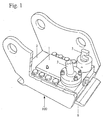
- Figure 1 is a perspective view of the device;
- Figures 2 and 3 are, respectively, a perspective view of the upper body and a perspective view of the lower body of the device prior to their assembly;
- Figures 4 and 5 are a front view and a longitudinal sectional view respectively, the latter taken along the plane X-X, of the entire device;
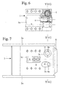
- Figures 6 and 7 are top views of the upper body and of the lower body of the device prior to their assembly;
- Figures 8 and 9 are cross-sectional views of the device, taken along the plane Y-Y thereof and referred to Figures 5, 6 and 7, with the safety retainer inserted and, respectively, extracted;
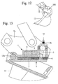
- Figures 10, 12 and 14 are sequential views illustrating three steps of the engagement of the shovel with an excavator arm provided with the new device;
- Figures 11, 13 and 15 are detailed longitudinal sectional views of the device in the corresponding steps shown schematically by Figures 10, 12 and 14.
-
- With reference to the accompanying drawings, the device according to the invention, generally designated by the
reference numeral 100, generally consists of two bodies: anupper body 1, at which the manual actuation lever 3, thehydraulic jack 2 and thepin 5 of the safety retainer are supported; and alower body 2, on the two sides of which the perforatedlugs 2A protrude parallel to each other for connection to the articulatedarm 12 of the excavator and to the actuation jack of theshovel 13; thebody 2 has substantially the shape of a flat box, open at the front and from which thebolt 6 which is slidably movable therein can protrude, said body being provided at the rear thereof with arecess 2B by means of which it straddles theretainer 13A of theexcavating tool 13 for the mutual rotation of the two elements (as in Figures 7 and 8) until engagement is completed. - Said
bolt 6, being pushed by a plurality ofhelical springs 7, constantly tends to protrude from the front side of thelower body 2 to the extent allowed by thewing 8 which is fixed on the bolt and by the opening 2C, which is provided in the upper part of the box in which said bolt slides, and determines the stroke of said bolt and allows saidwing 8 to enter thecavity 1A of theupper body 1 where when necessary it can be pushed by thehydraulic jack 4 to retract in contrast with thesprings 7. - The
bolt 6 is also provided withcircular holes manual actuation lever 3 and thepin 5 of the safety retainer, both of which are supported in theupper body 1 of the engagement device and reach said holes through theopenings - The opening 2D is elongated in the direction in which the bolt moves, as required by the variations in the inclination of the
lever 3, stably engaged in thehole 6A of the bolt and pivoted for this purpose to theupper body 1 with a sort of ball-and-socket joint. - The opening 2E is instead circular in shape so as to accommodate the guiding
bush 9 of thepin 5, which in turn engages thehole 6B of the bolt when such hole is concentric to the opening 2E (Figure 7), that is only when thebolt 6 has completed its engagement stroke. - As shown also by Figures 6, 8 and 9, the
pin 5, acting as a safety retainer and therefore preventing the accidental disengagement of the shovel or of any other tool applied to the arm of the excavator, is in practice the piston of a sort of single-acting hydraulic jack and is kept extended, i.e., so as to act as a retainer, by a return spring the thrust force of which is significantly lower than the force of the two ormore springs 7 that tend to keep thebolt 6 closed or in any case protruding from the box-like body 2. - Accordingly, since said jack is connected to the hydraulic system so that the retraction of the piston or
pin 5 occurs by means of the same oil causing the extension of thejack 4 and the retraction of the bolt, the required retraction of thepin 5 before the retraction of thebolt 6 being determined by the different thrust force of the springs that act on the two elements. - When the oil pressure ceases, said springs return the bolt to the protruding engagement position, and the return spring pushes the
pin 5 to the position in which it locks said bolt by entering thehole 6B that arranges itself at the pin. - A possible variation for obtaining the same automatic sequence in the retraction of the pin-
piston 5 and of thebolt 6 regardless of the thrust force of the respective springs consists in making the oil of the hydraulic system flow to thejack 4 of the bolt through a passage which is blocked by the pin-piston 5 until it is retracted completely by means of said oil. - As disclosed, the device according to the invention has been devised so that it can be actuated both hydraulically and manually. For manual intervention, it is possible to act on the
lever 3 with an extension pipe, whereas as regards the safety retainer, at the top of the pin-piston 5 ahook 5A is provided where, when necessary, it is possible to engage alever 11 by means of which said pin-piston can be easily lifted and also blocked in the retracted position for all the time required by the operator to manually retract thebolt 6. - As regards the pin-
piston 5, it should be noted that theportion 5B thereof lying directly below thehook 5A and protruding with said hook from thebush 10 when the pin-piston is in the retracted position, is red in color, so that the operator can detect any anomaly even from a distance. In practice, if the red collar remains visible after the excavating tool has been engaged manually or hydraulically, this means that the engagement has not been performed correctly and/or in any case the safety retainer has not been inserted. - Finally, it should be added that the device according to the invention, without altering the general characteristics that have been illustrated and described, might be susceptible of modifications and variations which are in any case within the scope of the appended claims.
- The disclosures in Italian Patent Application No. F02000A000006 from which this application claims priority are incorporated herein by reference.
- Where technical features mentioned in any claim are followed by reference signs, those reference signs have been included for the sole purpose of increasing the intelligibility of the claims and accordingly such reference signs do not have any limiting effect on the scope of each element identified by way of example by such reference signs.
Claims (11)
- A device for quick engagement and disengagement of an excavating tool in hydraulic excavators, of the type to be applied to the arm (12) of the excavator in order to engage the excavating tool by way of a bolt-like element (6) which is pushed by adapted springs (7) accommodated in a same box-like body (2), said bolt element (6) being lockable in an engaged condition by interference with an element (5) that lies transversely to its motion direction, characterized in that said bolt element (6) and the corresponding locking element (5) are provided so as to be actuatable in sequence hydraulically and/or mechanically in emergency cases, so as to prevent any failure or anomaly in the hydraulic system of the excavator alone, or of the excavating tool alone, hinder separation thereof and therefore immediate use of the still efficient part.
- The device according to claim 1, characterized in that the bolt element (6), in particular the element that is pushed constantly into the engaged condition by said appropriately provided springs (7) and in the opposite direction by temporary interventions of a jack (4) connected to the hydraulic system of the excavator, is provided with two holes (6A, 6B) or other engagement elements so as to receive in one of them the end of the lever (3) for emergency manual disengagement and in the other one the safety pin (5) which, retained thereat by the thrust of a spring, can be retracted both hydraulically and manually, since it also protrudes outside the device.
- The device according to the preceding claims, characterized in that the safety pin (5), constituting the locking element adapted to prevent accidental disengagement of the excavating tool or of any other implement engaged by the device on the excavator arm (12), is the piston of a single-acting hydraulic jack elastically biased so as to protrude in a safety condition by a spring the thrust force whereof is significantly lower than the thrust force of the set of springs (7) that keep the bolt element (6) engaged, said hydraulic jack being connected to the hydraulic system so that the retraction of the safety pin-piston (5) occurs due to the hydraulic pressure causing the elongation of the actuation jack (4) of the bolt element (6), the different thrust force between said springs (7) and the spring of the safety pin (5) forcing the safety pin-piston (5) to retract before the bolt element (6).
- The device according to the preceding claims, characterized in that it is generally constituted by two bodies:an upper body (1), in which the manual actuation lever (3), the hydraulic jack (4) and the pin (5) of the safety retainer are supported;a lower body (2), on the sides of which the perforated lugs (2A) protrude parallel to each other for connection to the articulated arm (12) of the excavator and to the jack actuating the shovel (13), said body (2) consisting of a sort of flat box open at the front and from which the bolt (6) sliding therein can protrude, said body being provided, at the rear thereof, with a recess (2B) by means of which it can straddle the retainer (13A) of the excavating tool (13) for the mutual rotation of the two elements until engagement is completed.
- The device according to the preceding claims, characterized in that the bolt (6), pushed by a plurality of helical springs (7), constantly tends to protrude from the front side of the lower body (2) to the extent allowed by the wing (8) fixed on the bolt and by the opening (2C) provided in the upper wall of the box in which the bolt slides and determines the stroke of said bolt and allows said wing (8) to enter the cavity (1A) of the upper body (1), where, when necessary, it can be pushed to retract by the hydraulic jack (4) in contrast with the springs (7).
- The device according to the preceding claims, characterized in that the bolt (6) is also provided with the circular holes (6A, 6B) for respectively accommodating the manual actuation lever (3) and the pin (5) of the safety retainer, both the lever (3) and the pin (5) being supported in the upper body (1) of the engagement device reach said holes through the openings (2D, 2E) provided in the upper wall of the box in which the bolt slides.
- The device according to claim 6, characterized in that the opening (2D) is elongated in the direction in which the bolt moves as required by the variations in the inclination of the lever (3) stably engaged in the hole (6A) of the bolt and pivoted for this purpose to the upper body (1), with a sort of ball-and-socket joint.
- The device according to claim 6, characterized in that the opening (2E) is instead circular in shape so as to accommodate the guiding bush (9) of the pin (5), which in turn engages the hole (6B) of the bolt when said hole is concentric with the opening (2E) (Figure 7), that is only when the bolt (6) has completed its engagement stroke.
- The device according to the preceding claims, characterized in that in order to allow the manual removal of the safety retainer according to claim 3, a hook (5A) is provided at the top of the pin-piston (5), which can engage, when necessary, a lever (11) by means of which said pin-piston can be easily lifted and also blocked in the retracted position for as long as required by the operator to retract the bolt (6) manually.
- The device according to the preceding claims, characterized in that the upper portion (5B) of the pin-piston (5), that is the portion lying directly under the hook (5A) and protruding with it from the bush (10) when the pin-piston is in the retracted position, is red in color, so as to allow the operator to visually detect any anomaly even from a distance; if the red collar is still visible after the hydraulic or manual engagement of the excavating tool, this means that the engagement has not been performed correctly and/or in any case the safety retainer has not been inserted.
- The device according to claim 3, characterized in that in order to achieve hydraulically the automatic retraction of the pin-piston (5) before the retraction of the bolt (6), the oil flow to the jack (4) acting on said bolt might be controlled by flow through a passage which is blocked by the pin-piston (5) until fully retracted by said oil.
Applications Claiming Priority (2)
| Application Number | Priority Date | Filing Date | Title |
|---|---|---|---|
| IT2000FO000006A IT1319865B1 (en) | 2000-03-27 | 2000-03-27 | DEVICE FOR HOOKING AND QUICK RELEASE OF THE EXCAVATION TOOL OF THE HYDRAULIC EXCAVATORS. |
| ITFO000006 | 2000-03-27 |
Publications (2)
| Publication Number | Publication Date |
|---|---|
| EP1138833A1 true EP1138833A1 (en) | 2001-10-04 |
| EP1138833B1 EP1138833B1 (en) | 2008-10-22 |
Family
ID=11442338
Family Applications (1)
| Application Number | Title | Priority Date | Filing Date |
|---|---|---|---|
| EP01106465A Expired - Lifetime EP1138833B1 (en) | 2000-03-27 | 2001-03-23 | Device for quick engagement and disengagement of the excavating tool in hydraulic excavators |
Country Status (6)
| Country | Link |
|---|---|
| EP (1) | EP1138833B1 (en) |
| AT (1) | ATE412088T1 (en) |
| DE (1) | DE60136238D1 (en) |
| DK (1) | DK1138833T3 (en) |
| ES (1) | ES2316409T3 (en) |
| IT (1) | IT1319865B1 (en) |
Cited By (7)
| Publication number | Priority date | Publication date | Assignee | Title |
|---|---|---|---|---|
| GB2381257A (en) * | 2001-10-26 | 2003-04-30 | Agco Gmbh & Co | Quick change frame for a front loader |
| EP1362957A1 (en) * | 2002-05-17 | 2003-11-19 | Deere & Company | Device for latching a tool to a lifting gear |
| US7654019B2 (en) | 2007-05-30 | 2010-02-02 | Brandt Industries Ltd. | Quick coupling mechanism for tool attachment |
| DE102010034738A1 (en) | 2009-08-21 | 2011-02-24 | Perwein Baumaschinen-Systeme Gmbh | Coupling device for fastening working device at excavator boom, has locking elements with front surfaces that comprise same inclination angle for forming parallel sliding faces, such that frictional tension between front surfaces is reduced |
| AT507598B1 (en) * | 2008-12-05 | 2012-03-15 | Wacker Neuson Linz Gmbh | DEVICE FOR REPLACEABLE TOOLS |
| AT510095B1 (en) * | 2010-07-06 | 2012-06-15 | Erna Kronberger | INSECT DEVICE |
| WO2015024981A1 (en) * | 2013-08-23 | 2015-02-26 | Geith International Limited | Safety coupling mechanism |
Families Citing this family (1)
| Publication number | Priority date | Publication date | Assignee | Title |
|---|---|---|---|---|
| IT202300018933A1 (en) | 2023-09-14 | 2025-03-14 | Carpenteria Biserni S R L | ATTACHMENT FOR CONNECTING A WORKING DEVICE TO A WORKING ARM |
Citations (6)
| Publication number | Priority date | Publication date | Assignee | Title |
|---|---|---|---|---|
| EP0506604A1 (en) * | 1991-01-10 | 1992-09-30 | Metallbau Und Spezialkonstruktionen In Metall, Michael Hand | Quick-acting coupling for temporarily connecting implements to an excavator boom |
| JPH06272273A (en) * | 1993-03-17 | 1994-09-27 | Sakato Kosakusho:Kk | Connector for construction work machine |
| JPH06272275A (en) * | 1993-03-17 | 1994-09-27 | Sakato Kosakusho:Kk | Connector for construction work machine |
| JPH08209732A (en) * | 1995-01-31 | 1996-08-13 | Sakato Kosakusho:Kk | Construction work machine coupling device |
| WO1998046835A1 (en) * | 1997-04-14 | 1998-10-22 | Baumaschinentechnik Gesellschaft Mbh | Device for attaching interchangeable items of equipment rapidly, for an excavator |
| EP1033447A2 (en) * | 1999-03-02 | 2000-09-06 | Mantovanibenne S.r.l. | A device for rapid tool coupling and release on tool arms. |
-
2000
- 2000-03-27 IT IT2000FO000006A patent/IT1319865B1/en active
-
2001
- 2001-03-23 DE DE60136238T patent/DE60136238D1/en not_active Expired - Fee Related
- 2001-03-23 DK DK01106465T patent/DK1138833T3/en active
- 2001-03-23 ES ES01106465T patent/ES2316409T3/en not_active Expired - Lifetime
- 2001-03-23 AT AT01106465T patent/ATE412088T1/en not_active IP Right Cessation
- 2001-03-23 EP EP01106465A patent/EP1138833B1/en not_active Expired - Lifetime
Patent Citations (6)
| Publication number | Priority date | Publication date | Assignee | Title |
|---|---|---|---|---|
| EP0506604A1 (en) * | 1991-01-10 | 1992-09-30 | Metallbau Und Spezialkonstruktionen In Metall, Michael Hand | Quick-acting coupling for temporarily connecting implements to an excavator boom |
| JPH06272273A (en) * | 1993-03-17 | 1994-09-27 | Sakato Kosakusho:Kk | Connector for construction work machine |
| JPH06272275A (en) * | 1993-03-17 | 1994-09-27 | Sakato Kosakusho:Kk | Connector for construction work machine |
| JPH08209732A (en) * | 1995-01-31 | 1996-08-13 | Sakato Kosakusho:Kk | Construction work machine coupling device |
| WO1998046835A1 (en) * | 1997-04-14 | 1998-10-22 | Baumaschinentechnik Gesellschaft Mbh | Device for attaching interchangeable items of equipment rapidly, for an excavator |
| EP1033447A2 (en) * | 1999-03-02 | 2000-09-06 | Mantovanibenne S.r.l. | A device for rapid tool coupling and release on tool arms. |
Non-Patent Citations (2)
| Title |
|---|
| PATENT ABSTRACTS OF JAPAN vol. 018, no. 683 (M - 1730) 22 December 1994 (1994-12-22) * |
| PATENT ABSTRACTS OF JAPAN vol. 1996, no. 12 26 December 1996 (1996-12-26) * |
Cited By (11)
| Publication number | Priority date | Publication date | Assignee | Title |
|---|---|---|---|---|
| GB2381257A (en) * | 2001-10-26 | 2003-04-30 | Agco Gmbh & Co | Quick change frame for a front loader |
| GB2381257B (en) * | 2001-10-26 | 2004-09-08 | Agco Gmbh & Co | Front loader |
| CZ303136B6 (en) * | 2001-10-26 | 2012-04-25 | Agco Gmbh & Co. | Front loader |
| EP1362957A1 (en) * | 2002-05-17 | 2003-11-19 | Deere & Company | Device for latching a tool to a lifting gear |
| US7001136B2 (en) | 2002-05-17 | 2006-02-21 | Deere & Company | Device for attaching an implement to a lifting unit |
| US7654019B2 (en) | 2007-05-30 | 2010-02-02 | Brandt Industries Ltd. | Quick coupling mechanism for tool attachment |
| AT507598B1 (en) * | 2008-12-05 | 2012-03-15 | Wacker Neuson Linz Gmbh | DEVICE FOR REPLACEABLE TOOLS |
| DE102010034738A1 (en) | 2009-08-21 | 2011-02-24 | Perwein Baumaschinen-Systeme Gmbh | Coupling device for fastening working device at excavator boom, has locking elements with front surfaces that comprise same inclination angle for forming parallel sliding faces, such that frictional tension between front surfaces is reduced |
| AT510095B1 (en) * | 2010-07-06 | 2012-06-15 | Erna Kronberger | INSECT DEVICE |
| WO2015024981A1 (en) * | 2013-08-23 | 2015-02-26 | Geith International Limited | Safety coupling mechanism |
| US10352020B2 (en) | 2013-08-23 | 2019-07-16 | Geith International Limited | Safety coupling mechanism |
Also Published As
| Publication number | Publication date |
|---|---|
| ITFO20000006A0 (en) | 2000-03-27 |
| DK1138833T3 (en) | 2009-03-02 |
| IT1319865B1 (en) | 2003-11-03 |
| DE60136238D1 (en) | 2008-12-04 |
| EP1138833B1 (en) | 2008-10-22 |
| ES2316409T3 (en) | 2009-04-16 |
| ITFO20000006A1 (en) | 2001-09-27 |
| ATE412088T1 (en) | 2008-11-15 |
Similar Documents
| Publication | Publication Date | Title |
|---|---|---|
| US8281506B2 (en) | Tool coupler assembly | |
| CA2539045C (en) | An excavator tool quick attachment device | |
| CN102272386B (en) | Work tool coupling arrangement | |
| US8974137B2 (en) | Quick coupler | |
| US10066359B2 (en) | Coupler device | |
| US20130160268A1 (en) | Quick coupler | |
| KR101096085B1 (en) | Excavator quick coupler | |
| CA2590464A1 (en) | Quick coupling mechanism for tool attachment | |
| CN113557336B (en) | connector | |
| EP3241949B1 (en) | Integrated excavator pin grabber quick coupler | |
| EP3312350A1 (en) | Connection apparatus for interconnecting an arm and a tool of a work machine | |
| EP0578447A1 (en) | Implement attachment coupler | |
| CN103189572B (en) | connection configuration | |
| EP1138833B1 (en) | Device for quick engagement and disengagement of the excavating tool in hydraulic excavators | |
| CN103154381B (en) | Connect configuration | |
| US20160251820A1 (en) | Work tool assembly and coupler | |
| US11952738B2 (en) | Attachment coupler | |
| KR101739779B1 (en) | Sagging preventing device for smart tongs in excavator | |
| AU723305B1 (en) | Adaptor hitch with locking pin | |
| US12497748B2 (en) | Attachment tool coupling assembly for a construction vehicle | |
| US20180251950A1 (en) | Wedge coupler lug brackets for coupling implements to excavation machines | |
| CA2997323A1 (en) | Wedge coupler lug brackets for coupling implements to excavation machines | |
| AU2008221549A1 (en) | Quick release coupling | |
| IE20040194U1 (en) | An excavator tool quick attachment device |
Legal Events
| Date | Code | Title | Description |
|---|---|---|---|
| PUAI | Public reference made under article 153(3) epc to a published international application that has entered the european phase |
Free format text: ORIGINAL CODE: 0009012 |
|
| AK | Designated contracting states |
Kind code of ref document: A1 Designated state(s): AT BE CH CY DE DK ES FI FR GB GR IE IT LI LU MC NL PT SE TR |
|
| AX | Request for extension of the european patent |
Free format text: AL;LT;LV;MK;RO;SI |
|
| 17P | Request for examination filed |
Effective date: 20020222 |
|
| AKX | Designation fees paid |
Free format text: AT BE CH CY DE DK ES FI FR GB GR IE IT LI LU MC NL PT SE TR |
|
| RAP1 | Party data changed (applicant data changed or rights of an application transferred) |
Owner name: CANGINI BENNE S.R.L. |
|
| 17Q | First examination report despatched |
Effective date: 20071115 |
|
| GRAP | Despatch of communication of intention to grant a patent |
Free format text: ORIGINAL CODE: EPIDOSNIGR1 |
|
| GRAS | Grant fee paid |
Free format text: ORIGINAL CODE: EPIDOSNIGR3 |
|
| GRAA | (expected) grant |
Free format text: ORIGINAL CODE: 0009210 |
|
| AK | Designated contracting states |
Kind code of ref document: B1 Designated state(s): AT BE CH CY DE DK ES FI FR GB GR IE IT LI LU MC NL PT SE TR |
|
| REG | Reference to a national code |
Ref country code: GB Ref legal event code: FG4D |
|
| REG | Reference to a national code |
Ref country code: CH Ref legal event code: EP |
|
| REG | Reference to a national code |
Ref country code: IE Ref legal event code: FG4D |
|
| REF | Corresponds to: |
Ref document number: 60136238 Country of ref document: DE Date of ref document: 20081204 Kind code of ref document: P |
|
| REG | Reference to a national code |
Ref country code: DK Ref legal event code: T3 |
|
| NLV1 | Nl: lapsed or annulled due to failure to fulfill the requirements of art. 29p and 29m of the patents act | ||
| REG | Reference to a national code |
Ref country code: ES Ref legal event code: FG2A Ref document number: 2316409 Country of ref document: ES Kind code of ref document: T3 |
|
| PG25 | Lapsed in a contracting state [announced via postgrant information from national office to epo] |
Ref country code: AT Free format text: LAPSE BECAUSE OF FAILURE TO SUBMIT A TRANSLATION OF THE DESCRIPTION OR TO PAY THE FEE WITHIN THE PRESCRIBED TIME-LIMIT Effective date: 20081022 |
|
| PGFP | Annual fee paid to national office [announced via postgrant information from national office to epo] |
Ref country code: DK Payment date: 20090324 Year of fee payment: 9 |
|
| PG25 | Lapsed in a contracting state [announced via postgrant information from national office to epo] |
Ref country code: PT Free format text: LAPSE BECAUSE OF FAILURE TO SUBMIT A TRANSLATION OF THE DESCRIPTION OR TO PAY THE FEE WITHIN THE PRESCRIBED TIME-LIMIT Effective date: 20090323 Ref country code: FI Free format text: LAPSE BECAUSE OF FAILURE TO SUBMIT A TRANSLATION OF THE DESCRIPTION OR TO PAY THE FEE WITHIN THE PRESCRIBED TIME-LIMIT Effective date: 20081022 Ref country code: NL Free format text: LAPSE BECAUSE OF FAILURE TO SUBMIT A TRANSLATION OF THE DESCRIPTION OR TO PAY THE FEE WITHIN THE PRESCRIBED TIME-LIMIT Effective date: 20081022 |
|
| PGFP | Annual fee paid to national office [announced via postgrant information from national office to epo] |
Ref country code: GB Payment date: 20090320 Year of fee payment: 9 |
|
| PGFP | Annual fee paid to national office [announced via postgrant information from national office to epo] |
Ref country code: BE Payment date: 20090319 Year of fee payment: 9 Ref country code: ES Payment date: 20090325 Year of fee payment: 9 |
|
| PLBE | No opposition filed within time limit |
Free format text: ORIGINAL CODE: 0009261 |
|
| STAA | Information on the status of an ep patent application or granted ep patent |
Free format text: STATUS: NO OPPOSITION FILED WITHIN TIME LIMIT |
|
| PG25 | Lapsed in a contracting state [announced via postgrant information from national office to epo] |
Ref country code: SE Free format text: LAPSE BECAUSE OF FAILURE TO SUBMIT A TRANSLATION OF THE DESCRIPTION OR TO PAY THE FEE WITHIN THE PRESCRIBED TIME-LIMIT Effective date: 20090122 |
|
| PGFP | Annual fee paid to national office [announced via postgrant information from national office to epo] |
Ref country code: DE Payment date: 20090529 Year of fee payment: 9 Ref country code: IT Payment date: 20090326 Year of fee payment: 9 |
|
| 26N | No opposition filed |
Effective date: 20090723 |
|
| PG25 | Lapsed in a contracting state [announced via postgrant information from national office to epo] |
Ref country code: MC Free format text: LAPSE BECAUSE OF NON-PAYMENT OF DUE FEES Effective date: 20090331 |
|
| PGFP | Annual fee paid to national office [announced via postgrant information from national office to epo] |
Ref country code: FR Payment date: 20090312 Year of fee payment: 9 |
|
| REG | Reference to a national code |
Ref country code: CH Ref legal event code: PL |
|
| PG25 | Lapsed in a contracting state [announced via postgrant information from national office to epo] |
Ref country code: LI Free format text: LAPSE BECAUSE OF NON-PAYMENT OF DUE FEES Effective date: 20090331 Ref country code: IE Free format text: LAPSE BECAUSE OF NON-PAYMENT OF DUE FEES Effective date: 20090323 Ref country code: CH Free format text: LAPSE BECAUSE OF NON-PAYMENT OF DUE FEES Effective date: 20090331 |
|
| BERE | Be: lapsed |
Owner name: CANGINI BENNE S.R.L. Effective date: 20100331 |
|
| PG25 | Lapsed in a contracting state [announced via postgrant information from national office to epo] |
Ref country code: GR Free format text: LAPSE BECAUSE OF FAILURE TO SUBMIT A TRANSLATION OF THE DESCRIPTION OR TO PAY THE FEE WITHIN THE PRESCRIBED TIME-LIMIT Effective date: 20090123 |
|
| REG | Reference to a national code |
Ref country code: DK Ref legal event code: EBP |
|
| GBPC | Gb: european patent ceased through non-payment of renewal fee |
Effective date: 20100323 |
|
| REG | Reference to a national code |
Ref country code: FR Ref legal event code: ST Effective date: 20101130 |
|
| PG25 | Lapsed in a contracting state [announced via postgrant information from national office to epo] |
Ref country code: FR Free format text: LAPSE BECAUSE OF NON-PAYMENT OF DUE FEES Effective date: 20100331 |
|
| PG25 | Lapsed in a contracting state [announced via postgrant information from national office to epo] |
Ref country code: DE Free format text: LAPSE BECAUSE OF NON-PAYMENT OF DUE FEES Effective date: 20101001 Ref country code: BE Free format text: LAPSE BECAUSE OF NON-PAYMENT OF DUE FEES Effective date: 20100331 |
|
| PG25 | Lapsed in a contracting state [announced via postgrant information from national office to epo] |
Ref country code: IT Free format text: LAPSE BECAUSE OF NON-PAYMENT OF DUE FEES Effective date: 20100323 Ref country code: GB Free format text: LAPSE BECAUSE OF NON-PAYMENT OF DUE FEES Effective date: 20100323 |
|
| PG25 | Lapsed in a contracting state [announced via postgrant information from national office to epo] |
Ref country code: DK Free format text: LAPSE BECAUSE OF NON-PAYMENT OF DUE FEES Effective date: 20100331 Ref country code: LU Free format text: LAPSE BECAUSE OF NON-PAYMENT OF DUE FEES Effective date: 20090323 |
|
| PG25 | Lapsed in a contracting state [announced via postgrant information from national office to epo] |
Ref country code: TR Free format text: LAPSE BECAUSE OF FAILURE TO SUBMIT A TRANSLATION OF THE DESCRIPTION OR TO PAY THE FEE WITHIN THE PRESCRIBED TIME-LIMIT Effective date: 20081022 |
|
| PG25 | Lapsed in a contracting state [announced via postgrant information from national office to epo] |
Ref country code: CY Free format text: LAPSE BECAUSE OF FAILURE TO SUBMIT A TRANSLATION OF THE DESCRIPTION OR TO PAY THE FEE WITHIN THE PRESCRIBED TIME-LIMIT Effective date: 20081022 |
|
| REG | Reference to a national code |
Ref country code: ES Ref legal event code: FD2A Effective date: 20111118 |
|
| PG25 | Lapsed in a contracting state [announced via postgrant information from national office to epo] |
Ref country code: ES Free format text: LAPSE BECAUSE OF NON-PAYMENT OF DUE FEES Effective date: 20100324 |