EP1138626A2 - Method and apparatus for use in lifting an object - Google Patents
Method and apparatus for use in lifting an object Download PDFInfo
- Publication number
- EP1138626A2 EP1138626A2 EP00307212A EP00307212A EP1138626A2 EP 1138626 A2 EP1138626 A2 EP 1138626A2 EP 00307212 A EP00307212 A EP 00307212A EP 00307212 A EP00307212 A EP 00307212A EP 1138626 A2 EP1138626 A2 EP 1138626A2
- Authority
- EP
- European Patent Office
- Prior art keywords
- lifting
- lifting eye
- pivot
- eye
- slot
- Prior art date
- Legal status (The legal status is an assumption and is not a legal conclusion. Google has not performed a legal analysis and makes no representation as to the accuracy of the status listed.)
- Withdrawn
Links
Images


Classifications
-
- B—PERFORMING OPERATIONS; TRANSPORTING
- B66—HOISTING; LIFTING; HAULING
- B66C—CRANES; LOAD-ENGAGING ELEMENTS OR DEVICES FOR CRANES, CAPSTANS, WINCHES, OR TACKLES
- B66C1/00—Load-engaging elements or devices attached to lifting or lowering gear of cranes or adapted for connection therewith for transmitting lifting forces to articles or groups of articles
- B66C1/10—Load-engaging elements or devices attached to lifting or lowering gear of cranes or adapted for connection therewith for transmitting lifting forces to articles or groups of articles by mechanical means
- B66C1/62—Load-engaging elements or devices attached to lifting or lowering gear of cranes or adapted for connection therewith for transmitting lifting forces to articles or groups of articles by mechanical means comprising article-engaging members of a shape complementary to that of the articles to be handled
- B66C1/66—Load-engaging elements or devices attached to lifting or lowering gear of cranes or adapted for connection therewith for transmitting lifting forces to articles or groups of articles by mechanical means comprising article-engaging members of a shape complementary to that of the articles to be handled for engaging holes, recesses, or abutments on articles specially provided for facilitating handling thereof
Definitions
- the present invention is directed generally to machine security and more particularly to lifting eyes for use in lifting heavy machinery.
- the transportation of heavy equipment such as air compressors and industrial power generators often requires an easily accessible lifting eye to facilitate the loading and unloading of the equipment onto a transportation vehicle, such as a flat bed trailer.
- the lifting eye is a rigid element which is either welded or bolted to the piece of equipment.
- the easy access to the typical lifting eye also facilitates the theft of equipment.
- the desire to reduce theft and generally improve the security of equipment has generated great interest in providing lifting systems which do not facilitate theft.
- One known system uses lockable trap doors to cover the lifting eye.
- the trap doors provide some measure of protection but remain vulnerable to attack in the same manner as conventional locked doors. Furthermore, the locked doors hinder the authorised used of the lifting eye.
- Other conventional systems provide a removable lifting eye. Removing the lifting eye inhibits theft of equipment but also introduces safety problems. If the removable lifting eye is not secured properly when reattached, the equipment may be dropped and damaged.
- a lifting eye for use in lifting an object comprising lifting eye member having an upper portion and a lower portion, said upper portion including an eye hole configured to receive a lifting hook; characterised in that said lower portion includes a pivot hole and a slot having two ends, there being a pivot member positioned in said pivot hole, the lifting eye member being capable of pivoting about said pivot member and there being a pivot stop positioned within said slot, wherein when the lifting eye member is pivoted about said pivot member, said slot moves about said pivot stop and the pivoting of the lifting eye member about said pivot member is limited by the pivot stop contacting one of the two ends of said slot.
- a method of lifting an object using a lifting eye characterised by the steps of rotating a lifting eye member affixed to the object to be lifted from a horizontal position to a vertical lifting position,affixing a lifting mechanism to the eye member; lifting the object; removing the lifting mechanism from the eye member and rotating the lifting eye member from the vertical lifting position to the horizontal position.
- a secure lifting eye assembly comprising a pivoting lifting eye having a lifting eye member having an upper portion and a lower portion, said upper portion including an eye hold configured to receive a lifting hook and said lower portion including a pivot hole and a slot having two ends, a pivot member positioned in said pivot hole, the lifting eye member being capable of pivoting about said pivot member and a pivot stop positioned within said slot; there being a canopy having a slot, the canopy being positioned to cover the lower portion of the lifting eye member; wherein when said pivoting eye is in a vertical lifting position, said upper portion of said lifting eye member extends through the slot in the canopy exposing said eye hole and when said pivoting lifting eye is in a horizontal position, said upper portion of said lifting eye member lies within said canopy obstructing said eye hole.
- a lifting eye member having an upper portion and a lower portion, said upper portion including an eye hole configured to receive a lifting hook and said lower portion including at least two openings, each opening being configured to receive a holding member; at least one support fixably connected to an object to be lifted, said support including at least two openings, each opening being configured to receive a holding member; and at least two holding members, each holding member passing through an opening in said support and an opening in said lifting eye member.
- Figure 1 illustrates a pivoting lifting eye 1 according to a first embodiment including a lifting eye member 3.
- the lifting eye member 3 is illustrated in both a vertical lifting position A and in a horizontal non-lifting position B.
- the lifting eye member 3 has an upper portion 5 and a lower portion 7.
- the upper portion 5 includes an eye hole 9 which is configured to receive a conventional lifting hook.
- the eye hold 9 may be circular, ellipsoidal, oval or any other shape that permits passage of a hook.
- the lower portion 7 includes a pivot hole 11 and an arcuate slot 13.
- the pivot hole 11 is sized to receive a pivot member 51A while the arcuate slot 13 is sized to receive a pivot stop 51B.
- the pivot member 51A and the pivot stop 51B may be any object that allows the lifting eye member 3 to pivot.
- the pivot member 51A and the pivot stop 51B may be bolts, rods, bars, dowels or any combination thereof.
- optional bushings 15A, 15B may be used in both pivot the hole 11 and the slot 13.
- Locking members 57 may be used to secure the pivot member 51A and the pivot stop 51B.
- the preferred locking member is a nut, however any device suitable for securing the locking member may be used.
- the locking member may be a cotter pin or a screw cap.
- optional "bushings 15A, 15B may be used in both the pivot hole 11 and the slot 13.
- the optional bushing 15A is adapted to fit into the pivot hole 11 while the optional bushing 15B is sized to fit into the slot 13.
- the lifting member 3 is supported and attached to the machine to be lifted by at least one support 17A.
- two supports 17A, 17B are used.
- Each support 17A, 17B has an upper portion 19 and a lower portion 21.
- the upper portion 19 has upper and lower openings 23A, 23B.
- the upper opening 23A is sized to receive the pivot member.
- the pivot member 51A passes through the upper opening 23A in support 17A, through the bushing 15A in the pivot hole 11 in the lifting member 3 and through upper opening 23A in support 17B.
- the pivot member 51A is secured with locking member 53A.
- the pivot stop 51B passes through the lower opening 23B in support of 17A, through the bushing 15B in the slot 13 in the lifting member 3 and through the lower opening 23B in support 17B.
- the pivot stop 51B is secured with locking member 53B.
- the lower portion 21 includes mounting holes 25 through which bolts or the like may be used to mount the supports 17A, 17B to the object to be lifted. Alternatively, the lower portion 25 may be welded or adhesively mounted to the object to be lifted.
- the lifting eye member 3 In the non-lifting configuration, the lifting eye member 3 is in a horizontal position B. When it is desired to lift an object, the lifting member eye 3 is pivoted approximately 90 degrees to the vertical position A. A hook can then be inserted in to the eye hole 9, and the object lifted.
- the pivot stop 51B prevents the lifting member eye 3 from over-rotating, thereby adding stability to the lifting eye 1. Additionally, the pivot stop 51B improves safety by providing a second support in case of the failure of the pivot member.
- the lower portion 7 has a larger mass than the upper portion 5. This offset mass configuration results in the lifting member 3 remaining in a vertical lifting position A unless a force is applied to rotate to the horizontal position B. When not required for lifting an object, the lifting member 3 is preferably secured in horizontal position B.
- FIG. 2 illustrates a second embodiment that can be used when there is a lower threat of theft.
- the pivoting lifting member 3 is replaced by a fixed, non-rotating lifting member 27.
- the fixed lifting member 27 has an upper portion 28 and a lower portion 30.
- the upper portion 28 includes an eye hole 9 and upper and lower openings sized to receive holding members 55.
- the holding members secure the fixed lifting member 27 to supports 17A, 17B.
- the holding members 55 may be any object that can be used to secure the fixed lifting eye member 27 to the supports 17A, 17B.
- the holding members may be bolts, rods, bars, dowels or any combination thereof.
- Locking members 57 may be used to secure the holding members 55.
- the preferred locking member is a nut, however any device suitable for securing the locking member may be used.
- the locking member may be a cotter pin or a screw cap.
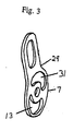
- the rotating lifting eye 1 may include an alternative second lifting eye member 29 as shown in Figure 3.
- the second lifting eye member 29 is similar to the first lifting eye member 3 in most respects except 'that the second lifting eye 29 includes a second arcuate slot 31 and a second pivot stop (not shown)
- the use of a second slot 31 and a second pivot stop further improves safety and reliability in case of failure of the pivot member or the first pivot stop.
- the two slots 13, 31 slide simultaneously about the two pivot stops.
- the lifting eye 1 may be mounted to an object 39, as shown in Figure 4.
- the secure lifting eye assembly 33 of Figure 4 includes a canopy 35 for covering the lifting eye 1.
- the canopy 35 is rotatably affixed to the object 39 by hinges 37.
- the canopy may be affixed to the object by any conventional means allowing quick access to the underlying lifting eye 1.
- the canopy 35 may include an optional handle 41.
- a lock 43 which may be used to secure the canopy 35 to the object 39.
- the lock 43 is built into the object 39.
- the arrangement is shown for illustration purposes only and is not intended to be limiting. Any suitable locking configuration may be used.
- a locking mechanism integrated into the canopy 35 or a conventional exterior padlock system may be used.
- the canopy 35 may include a slot 45.
- the slot 45 is configured so that the upper portion 5 of the lifting eye member 3 protrudes through the slot 45, fully exposing the eye hole 9 when the lifting eye member 3 is in the vertical lifting position A.
- the upper portion 5 of the lifting eye member 3 is secure under the canopy 35.
- the eye hole 9 is covered by the canopy 35, preventing its use and thereby reducing the likelihood of theft.
Landscapes
- Engineering & Computer Science (AREA)
- Mechanical Engineering (AREA)
- Seats For Vehicles (AREA)
- Load-Engaging Elements For Cranes (AREA)
Abstract
Description
wherein when the lifting eye member is pivoted about said pivot member, said slot moves about said pivot stop and the pivoting of the lifting eye member about said pivot member is limited by the pivot stop contacting one of the two ends of said slot.
Claims (20)
- A lifting eye (1) for use in lifting an object comprising a lifting eye member (3) having an upper portion (5) and lower portion (7), said upper portion including an eye hole (9) configured to receive a lifting hook; characterised in that said lower portion (7) includes a pivot hole (11) and a slot (13) having two ends, there being a pivot member (51A)positioned in said pivot hole, the lifting eye member (3) being capable of pivoting about said pivot member (51A), and there being a pivot stop (51B) positioned within said slot (13),wherein when the lifting eye member (3) is pivoted about said pivot member (51A), said slot (13) moves about said pivot stop (51B)and the pivoting of the lifting eye member about said pivot member is limited by the pivot stop contacting one of the two ends of said slot.
- A lifting eye according to claim 1, wherein said pivot member (51A) is a bolt.
- A lifting eye according to claim 1 or 2, wherein said pivot stop (51B) is a bolt.
- A lifting eye according to claim 1, 2 or 3, further comprising a bushing (15A) positioned in said pivot hole (11) between said pivot member (51A) and said lifting eye member (3).
- A lifting eye according to any one of claims 1 to 4, further comprising a bushing (15A) positioned in said slot between said lifting eye member and said pivot stop (15B).
- A lifting eye according to any one of claims 1 to 5, wherein said slot (13) has an arcuate shape.
- A lifting eye according to any one of claims 1 to 6, wherein said lifting eye member (29) has a second slot (31) and a second pivot stop.
- A lifting eye according to any one of claims 1 to 7, further comprising a first support (17A) for connection to the object (39), wherein said pivot member (51A) is secured to said support.
- A lifting eye according to claim 8, wherein said pivot stop (51B) is connected to said first support.
- A lifting eye according to claim 8 or 9, further comprising a second support (17B) for connection to the object (39) and positioned on an opposite side of said lifting eye member from said first support.
- A lifting eye according to claim 10, wherein said pivot member (51A) is connected to said first and second supports.
- A lifting eye according to any one of the preceding claims, wherein the mass of the lower portion (7) is greater than the mass of the upper portion (5).
- A lifting eye according to claim 12, wherein the pivot hole (11) is positioned in the lifting eye member so that said lifting eye has an offset mass configuration.
- A lifting eye according to any one of the preceding claims, wherein the length of the slot (13) limits the amount of rotation of said lifting eye member (3) around said pivot member (51A) to approximately 90 degrees.
- A method of lifting an object using a lifting eye; characterised by the steps of rotating a lifting eye member (3) affixed to the object (39) to be lifted from a horizontal position to a vertical lifting position, affixing a lifting mechanism to the eye member, lifting the object, removing the lifting mechanism from the eye member, and rotating the lifting eye member from the vertical lifting position to the horizontal position.
- A method according to claim 15, wherein the steps of rotating comprise rotating said lifting eye member (3) about a pivot member (51A) in a pivot hole (11) and a pivot stop (51B) in a slot (13).
- A secure lifting eye assembly comprising a pivoting lifting eye (1) having a lifting eye member (3) having an upper portion (5) and a lower portion (7), said upper portion including an eye hole (19) configured to receive a lifting hook and said lower portion including a pivot hole (11) and a slot (13) having two ends, a pivot member (51A) positioned in said pivot hole, the lifting eye member being capable of pivoting about said pivot member and a pivot stop (51B) positioned within said slot; there being a canopy (35) having a slot (45), the canopy being positioned to cover the lower position of the lifting eye member; wherein when said lifting eye member extends through the slot in the canopy exposing said eye hole and when said pivoting lifting eye is in a horizontal position, said upper portion of said lifting eye member lies within said canopy obstructing said eye hole.
- A lifting eye (1) comprising a lifting eye member (3) having an upper portion (5) and a lower portion (7), said upper portion including an eye hole (9) configured to receive a lifting hook and said lower portion including at least two openings (11, 12), each opening being configured to receive a holding member; at least one support (17A) fixably connected to an object (39) to be lifted, said support including at least two openings, each opening being configured to receive a holding member; and at least two holding members, each holding member passing through an opening in said support and an opening in said lifting eye member.
- A lifting eye according to claim 18, wherein one of said openings in said lifting eye member is a hole and one of said openings in said lifting eye member is an arcuate slot (13).
- A lifting eye according to claim 18, wherein all of said openings in said lifting eye member are holes.
Applications Claiming Priority (5)
| Application Number | Priority Date | Filing Date | Title |
|---|---|---|---|
| US19237000P | 2000-03-27 | 2000-03-27 | |
| US192370P | 2000-03-27 | ||
| US62979700A | 2000-07-31 | 2000-07-31 | |
| 2003-03-28 | |||
| US629797 | 2003-07-30 |
Publications (2)
| Publication Number | Publication Date |
|---|---|
| EP1138626A2 true EP1138626A2 (en) | 2001-10-04 |
| EP1138626A3 EP1138626A3 (en) | 2003-08-27 |
Family
ID=27668262
Family Applications (1)
| Application Number | Title | Priority Date | Filing Date |
|---|---|---|---|
| EP00307212A Withdrawn EP1138626A3 (en) | 2000-03-27 | 2000-08-23 | Method and apparatus for use in lifting an object |
Country Status (1)
| Country | Link |
|---|---|
| EP (1) | EP1138626A3 (en) |
Cited By (1)
| Publication number | Priority date | Publication date | Assignee | Title |
|---|---|---|---|---|
| US10934136B1 (en) * | 2015-08-28 | 2021-03-02 | Eric Andrew Baier | Hardtop removal bracket and methods of use thereof |
Family Cites Families (2)
| Publication number | Priority date | Publication date | Assignee | Title |
|---|---|---|---|---|
| US5052735A (en) * | 1988-10-14 | 1991-10-01 | Tsudakoma Kogyo Kabushiki Kaisha | Auto-clamper for pallets |
| JPH09235818A (en) * | 1996-03-04 | 1997-09-09 | Shibata Kensetsu Kogyo Kk | Construction panel and metal used for it |
-
2000
- 2000-08-23 EP EP00307212A patent/EP1138626A3/en not_active Withdrawn
Cited By (1)
| Publication number | Priority date | Publication date | Assignee | Title |
|---|---|---|---|---|
| US10934136B1 (en) * | 2015-08-28 | 2021-03-02 | Eric Andrew Baier | Hardtop removal bracket and methods of use thereof |
Also Published As
| Publication number | Publication date |
|---|---|
| EP1138626A3 (en) | 2003-08-27 |
Similar Documents
| Publication | Publication Date | Title |
|---|---|---|
| US6283455B1 (en) | Multi-mission recovery device | |
| US7543466B2 (en) | Security link | |
| DE69010760T2 (en) | Vehicle seat lock with a receiving device. | |
| US6059266A (en) | Recovery device | |
| US6164508A (en) | Vehicle rack systems and methods | |
| US4632446A (en) | Locking device for a pickup storage box door | |
| US20050067812A1 (en) | Monolithic, double-ball hitch | |
| US5415058A (en) | Removable tailgate locking device | |
| US5067626A (en) | Trash receptacle adapted for rotatable mounting having integral locking and supporting means | |
| US6695553B1 (en) | Device for securing a container to a hoist | |
| US7004337B2 (en) | Foldable cab/pivot unit for a tower crane | |
| US6520067B1 (en) | Hydraulic piston locking device | |
| US20120103032A1 (en) | Security cover for cargo containers | |
| US5156517A (en) | Removable hoist system | |
| US4669618A (en) | Lifting assembly | |
| US20160304134A1 (en) | Locking device and assembly for use with a truck tailgate mounting hub | |
| US20220314896A1 (en) | Attachment system | |
| EP0707999A1 (en) | A motor vehicle folding seat assembly and securing means therefor | |
| US4126208A (en) | Adjustable lock for mast hanger | |
| US5673834A (en) | Dolly lock apparatus | |
| US5836182A (en) | Spare tire locking device | |
| GB2262119A (en) | Lockable access cover | |
| GB2165507A (en) | A security device | |
| WO2003054331A1 (en) | A container lock device | |
| US12528319B1 (en) | System for displaceable mounting of outboard utility equipment to vehicle with in situ access to vehicle compartment |
Legal Events
| Date | Code | Title | Description |
|---|---|---|---|
| PUAI | Public reference made under article 153(3) epc to a published international application that has entered the european phase |
Free format text: ORIGINAL CODE: 0009012 |
|
| AK | Designated contracting states |
Kind code of ref document: A2 Designated state(s): AT BE CH CY DE DK ES FI FR GB GR IE IT LI LU MC NL PT SE |
|
| AX | Request for extension of the european patent |
Free format text: AL;LT;LV;MK;RO;SI |
|
| PUAL | Search report despatched |
Free format text: ORIGINAL CODE: 0009013 |
|
| AK | Designated contracting states |
Designated state(s): AT BE CH CY DE DK ES FI FR GB GR IE IT LI LU MC NL PT SE |
|
| AX | Request for extension of the european patent |
Extension state: AL LT LV MK RO SI |
|
| AKX | Designation fees paid | ||
| REG | Reference to a national code |
Ref country code: DE Ref legal event code: 8566 |
|
| STAA | Information on the status of an ep patent application or granted ep patent |
Free format text: STATUS: THE APPLICATION IS DEEMED TO BE WITHDRAWN |
|
| 18D | Application deemed to be withdrawn |
Effective date: 20040228 |