EP1138579A2 - Vehicle fender structure - Google Patents
Vehicle fender structure Download PDFInfo
- Publication number
- EP1138579A2 EP1138579A2 EP01108138A EP01108138A EP1138579A2 EP 1138579 A2 EP1138579 A2 EP 1138579A2 EP 01108138 A EP01108138 A EP 01108138A EP 01108138 A EP01108138 A EP 01108138A EP 1138579 A2 EP1138579 A2 EP 1138579A2
- Authority
- EP
- European Patent Office
- Prior art keywords
- fender
- vehicle
- transverse direction
- wall portion
- structure according
- Prior art date
- Legal status (The legal status is an assumption and is not a legal conclusion. Google has not performed a legal analysis and makes no representation as to the accuracy of the status listed.)
- Granted
Links
Images


Classifications
-
- B—PERFORMING OPERATIONS; TRANSPORTING
- B62—LAND VEHICLES FOR TRAVELLING OTHERWISE THAN ON RAILS
- B62D—MOTOR VEHICLES; TRAILERS
- B62D25/00—Superstructure or monocoque structure sub-units; Parts or details thereof not otherwise provided for
- B62D25/02—Side panels
-
- B—PERFORMING OPERATIONS; TRANSPORTING
- B60—VEHICLES IN GENERAL
- B60R—VEHICLES, VEHICLE FITTINGS, OR VEHICLE PARTS, NOT OTHERWISE PROVIDED FOR
- B60R21/00—Arrangements or fittings on vehicles for protecting or preventing injuries to occupants or pedestrians in case of accidents or other traffic risks
- B60R21/34—Protecting non-occupants of a vehicle, e.g. pedestrians
- B60R2021/343—Protecting non-occupants of a vehicle, e.g. pedestrians using deformable body panel, bodywork or components
Definitions
- the invention relates to the structure of a fender portion of a vehicle and, in particular, to the structure of a fender portion of a vehicle in which a fender is attached to a structural member of a vehicle such as an automobile.
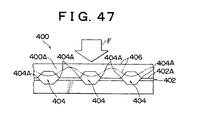
- a plurality of angular holes 404 are punched in a step portion 402 formed in a wall portion 400A on the inner side in the vehicle transverse direction of a front fender 400 and angular portions 404A of the angular holes 404 are matched at break line portions 402A of the step portion 402. Therefore, in this front fender 400, the break line portions 402A are easily deformed due to the forming of the angular portions 404A and, as is shown by the double dot chain line in Fig. 47, there is a large amount of deformation in a vertex 406 of the front fender 400 which corresponds to the angular holes 404. As a result, in this vehicle fender structure even if a colliding body impacts on the vertex 406 of the front fender 400, which corresponds to the angular holes 404, it is possible for the impact energy to be reliably absorbed.
- this type of vehicle fender structure is structured so that, if a colliding body (impactor) impacts or strikes on the vertex 406 of the front fender 400 which corresponds to the angular holes 404, or if a colliding body impacts on the vertex 406 of the front fender 400 which does not correspond to the angular holes 404, the wall portion 400A on the inner side in the vehicle transverse direction of a front fender 400 is deformed by buckling in the vertical direction thereby absorbing the impact energy.
- buckling deformation in the vertical direction in the wall portion on the inner side in the transverse direction of the vehicle generated by the impact load substantially from above i.e.
- the first aspect of this invention is a structure for a fender portion of a vehicle in which a fender is mounted on a structural member of a vehicle using a mounting member, wherein at least the fender from out of the fender and the mounting member is moved relatively to the structural member by an impact load from a substantially upward direction.
- the mounting member comprises a nut plate and a fastening bolt, and for a hole to be formed in the structural member such that the mounting member is capable of being moved by an impact load from a substantially upward direction.
- the mounting member comprises a nut that is fixed to the structural member and a fastening bolt, and for a hole to be formed in the fender such that the fender is capable of being moved relative to the mounting member by an impact load from a substantially upward direction.
- the fender nut when an impact load is applied substantially from an upward direction, the fender nut is able to move easily in the shearing direction of the fastened portion relative to the nut fixed to the structural member and the fastening bolt via the hole formed in the fender.
- the second aspect of the invention is a structure for a fender portion of a vehicle in which a fender is mounted on a structural member of a vehicle, wherein the fender portion structure is provided with a first deforming portion in the fender that is deformed by an impact load from a substantially upward direction, a second deforming portion in the structural member that is deformed by an impact load from a substantially upward direction, and a deformation suppressing means that suppresses a deformation of the first deforming portion and the second deforming portion at a predetermined load or less.
- the first deforming portion prefferably be a tongue shaped piece in the fender and the second deforming portion to be a tongue shaped piece in the structural member, and the deformation suppressing means to be a supporting piece provided below the tongue shape piece in the structural member.
- the tongue shaped piece in the structural member may be provided with a weakened portion that acts as a trigger for deformation.
- the third aspect of the invention is a structure for a fender portion of a vehicle in which a fender is mounted on a structural member of a vehicle, wherein the fender portion structure is provided with a weakened portion on an outside surface in the vehicle transverse direction of the fender that becomes the base point of deformation caused by an impact load from a substantially upward direction, and with a linking member that links the vicinity of the weakened portion with the structural member.
- the fender is deformed by an impact load from a substantially upward direction with the weakened portion in the vehicle outer side surface as a base point.
- the linking member linking the vicinity of the weakened portion with the structural member becomes a support pillar and the weakened portion of the fender definitely becomes the base point of the deformation, it is possible to reduce the amount of buckling deformation of the fender generated by the impact load.
- it is possible to absorb the impact energy within the range in which buckling deformation is possible of the fender it is possible to obtain a low deformation load until the end of the deformation and the performance to mitigate the impact force is improved.
- the weakened portion prefferably be a concave groove extending in the longitudinal direction of the vehicle.
- the concave groove can double as a concave groove for attaching the ornamental molding and as the weakened portion which becomes the base point of the deformation of the fender.
- the fourth aspect of the invention is a structure for a fender portion of a vehicle in which a fender is mounted on a structural member of a vehicle, wherein a height in the vertical direction of the vehicle where the mounting portion of the fender is mounted on the structural member is set lower than a height in the vertical direction of the vehicle of a top surface of the structural member, and a portion that is thinner in the vertical direction of the vehicle than a framework of a hood is provided above the top surface of the structural member.
- rigidity ensuring means prefferably be provided in an area of the hood facing the mounting portion of the fender.
- the rigidity ensuring means prefferably be a flange portion that hangs down and is formed at an endpoint on the vehicle outer side of the hood.
- the rigidity ensuring means prefferably be a hood auxiliary framework that is formed at an outer side in the transverse direction of the vehicle of the thinly formed hood portion and whose thickness in the vertical direction of the vehicle is thicker than the thinly formed hood portion.
- the rigidity ensuring means as a hood auxiliary framework that is formed at the vehicle outer side of the thinly formed hood portion and whose thickness in the vertical direction of the vehicle is thicker than the thinly formed hood portion, it is possible to secure sufficient rigidity of the endpoints on the vehicle outer side of the hood.
- the fender prefferably be provided with a sloping surface in an inner wall portion in the transverse direction of the vehicle that slopes from the outer side of the vehicle at the top to the inner side of the vehicle at the bottom.
- the fender prefferably be provided with a substantially triangular shaped convex rib in an inner wall portion in the transverse direction of the vehicle that runs toward an inner side in the vehicle transverse direction.
- the fifth aspect of the invention is a structure for a fender portion of a vehicle in which a fender is mounted on a structural member of a vehicle, wherein the structure is provided with component force generating means for separating force input into a fender from a substantially upward direction into plurality of component forces that are offset in the transverse direction of the vehicle and thus controlling the directions in which the fender is crushed.
- a component force generating means to separate the input into the fender from a substantially upward direction into a plurality of component forces that are offset in the vehicle transverse direction, it is possible to control the directions in which the fender is crushed.
- the vehicle body is constructed such that, upon an input from a substantially upward direction being received by the fender, the hood and the fender interfere with each other and the deformation load increases, the direction in which the fender is crushed is controlled so as to be a direction in which the hood and the fender do not interfere with each other. Therefore, it is possible to suppress any increase in the deformation load and to improve the performance to mitigate the impact force.
- the vehicle body is constructed such that deformation load in the fender increases when the amount of deformation of the fender increases, then the direction in which the fender is crushed is controlled so as to be a direction in which the fender deformation load does not increase. Therefore, it is possible to suppress any increase in the deformation load and to improve the performance to mitigate the impact force.
- the component force generating means prefferably comprise at least two linking wall portions that face each other in the transverse direction of the vehicle.
- linking wall portions prefferably integral with the fender.
- At least one of the linking wall portions not to be formed rectilinearly as seen from the front of the vehicle.
- linking wall portions two facing linking wall portions not to be formed rectilinearly as seen from the front of the vehicle.
- linking wall portions it is possible, in the linking wall portions, to set the respective bending directions of the two facing linking wall portions to be different from each other in the transverse direction of the vehicle.
- the sixth aspect of the invention is a structure for a fender portion of a vehicle in which a fender is mounted on a structural member of a vehicle, wherein the structure is provided with: a general surface between the structural member and a parting portion between the hood that is formed as a sloping wall portion that slopes downward toward the inner side in the vehicle transverse direction; a fender panel whose attachment portion where the fender panel attaches to the structural member is substantially horizontal; and, between the sloping wall portion and the mounting portion, with a folding portion that is folded by a load from a substantially upward direction and a hole that is contracted when the folding portion is folded.
- the portion for mounting on the structural member is not provided on a sloping wall portion as in the conventional structure, the engine room is not made any smaller by protruding of the mounting portion of the fender panel toward the inner side in the vehicle transverse direction. Moreover, when a load is applied from a substantially upward direction, the folding portion between the sloping wall portion and the mounting portion is folded and the hole portion is contracted, resulting in the deformation load being reduced. Therefore, the ability to absorb impact is improved.
- the folding portions prefferably be provided at least to the front and rear in the longitudinal direction of the vehicle of the mounting portion, and for the hole portion to be provided at an outer side in the vehicle transverse direction of the mounting portion.
- the portion for mounting on the structural member is not provided on a sloping wall portion as in the conventional structure, the engine room is not made any smaller by protruding of the mounting portion of the fender panel toward the inner side in the vehicle transverse direction.
- the folding portions provided at least to the front and rear sides of the mounting portion are folded and absorb the impact and the hole portion provided at the outer side in the vehicle transverse direction of the mounting portion is contracted, resulting in the deformation load being reduced. Therefore, the ability to absorb impact is improved.
- the length of a straight line between a bottom end and a top end of the folding portion before it is folded is substantially equal to that of a straight line between a bottom end and a top end of the folding portion after it is folded.
- a recessed portion is also possible for a recessed portion to be provided in an area opposing the folding portion of the structural member.
- the folding portion prefferably be provided at an outer side in the vehicle transverse direction of the mounting portion, and the for hole portions to be provided to the front and rear in the longitudinal direction of the vehicle of the mounting portion.
- the portion for mounting on the structural member is not provided on a sloping wall portion as in the conventional structure, the engine room is not made any smaller by protruding of the mounting portion of the fender panel toward the inner side in the vehicle transverse direction.
- the folding portion provided at least to the outer side in the vehicle transverse direction of the mounting portion is folded and absorbs the impact and the hole portion provided to the front and rear sides of the mounting portion is contracted, resulting in the deformation load being reduced. Therefore, the ability to absorb impact is improved.
- the folding portion is formed separately from the fender panel.
- the shape of the folding portion can be set without having to consider the formability of the fender panel.
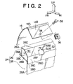
- the arrow FR shows the direction of the front of the vehicle
- the arrow UP shows the direction of the top of the vehicle
- the arrow IN shows the direction of the inside of the vehicle.
- a boundary 16 between a hood panel 12 and a fender 14 of a vehicle body 10 extends in the longitudinal direction of the vehicle at both end portions in the transverse direction of the vehicle of a front hood 18.
- a hood inner panel 20 is provided extending in the vehicle longitudinal direction at the bottom surface side of the outer side portions in the vehicle transverse direction of the hood panel (also known as the hood outer panel) 12.
- the cross sectional configuration of the hood inner panel 20 as seen from the vehicle longitudinal direction is formed generally in a hat shape with the open portion thereof facing upward.
- An inner flange 20A formed protruding outward at the inner side in the vehicle transverse direction of the open portion is joined to a bottom surface 12A of the hood panel 12 by an adhesive 13.
- An outer peripheral edge 12B of the hood panel 12 in the vehicle transverse direction is fixed by a hemming process to an outer flange 20B formed protruding outward at the outer side in the vehicle transverse direction of the open portion of the hood inner panel 20.
- a closed cross section portion 21 formed from the hood panel 12 and the hood inner panel 20 forms the framework of the hood panel 12 and is also provided with load monodeformation characteristics capable of absorbing sufficient impact even if a colliding body S collides with only the hood panel 12.
- An apron upper member 24 which serves as a structural member of the vehicle body 10 in the vehicle longitudinal direction is provided below the boundary 16 between the hood panel 12 and the fender 14.
- the apron upper member 24 is formed from an apron upper member upper 26, which forms the top portion of the apron upper member 24, and an apron upper member lower 28, which forms the bottom portion of the apron upper member 24.
- the apron upper member upper 26 is formed with a trapezoid shaped cross section whose open portion faces downward and a flange 26B, which is directed toward the outer side in the vehicle transverse direction, is formed at the bottom end portion of the outer wall portion 26A in the vehicle transverse direction.
- the apron upper member lower 28 is formed with an L shaped cross section and a horizontal wall portion 28B, which is directed toward the outer side in the vehicle transverse direction, is formed at the top end portion of a vertical wall portion 28A.
- the flange 26B of the apron upper member upper 26 and a distal end portion 28C of the horizontal wall portion 28B of the apron upper member lower 28 are welded together.
- a bottom end edge portion 26D of an inner wall portion 26C in the vehicle transverse direction of the apron upper member upper 26 is welded to an inner surface 28D in the vehicle transverse direction of the top end edge portion of the vertical wall portion 28A of the apron upper member lower 28.
- the apron upper member 24 forms a closed cross sectional portion 30 that extends in the vehicle longitudinal direction through the apron upper member upper 26 and the apron upper member lower 28.
- the top end portion of the inner wall portion 26C in the vehicle transverse direction and the inner end portion in the vehicle transverse direction of a top wall portion 26E of the apron upper member upper 26 are joined by a sloping wall portion 26F.
- Holes 32 are formed at predetermined intervals in the vehicle longitudinal direction in the sloping wall portion 26F.
- a bottom portion 32A of these holes 32 is formed in a rectangular shape with the bottom portion of the bottom portion 32A punched out of the top end portion of the inner side wall portion 26C in the vehicle transverse direction.
- the top portion 32B of the holes 32 is formed in a slit shape extending vertically from the center portion in the longitudinal direction of the bottom portion 32A.
- the inner edge portion 14A in the vehicle transverse direction of the fender 14 facing the outer edge portion 12B in the vehicle transverse direction of the hood panel 12 is curved in an arc shape, and a sloping wall portion 14B is provided extending from an inner edge portion 14A in the vehicle transverse direction toward the sloping wall portion 26F of the apron upper member upper 26.
- mounting holes 34 are punched at predetermined intervals in the vehicle longitudinal direction in the vicinity of the lower end portion of the sloping wall portion 14B in the fender 14.
- Nut plates 36 serving as mounting members are fixed by bolts 38 serving as mounting members to the mounting holes 34.
- nuts 40 are fixed to a bottom piece 36A of the nut plate 36.
- the sloping wall portion 14B of the fender 14 and the sloping wall portion 26F of the apron upper member upper 26 are sandwiched between the top piece 36B and the bottom piece 36A of the nut plate 36. This results in the sloping wall portion 14B of the fender 14 being fixed to the sloping wall portion 26F of the apron upper member upper 26.
- a colliding body S collides with the boundary 16 between the hood panel 12 and the fender 14 and the load acts substantially from an upward direction in substantially a downward direction (i.e. in the direction shown by the arrow A in Fig. 1), the area in the vicinity of the boundary 16 of the hood panel 12 and the area in the vicinity of the boundary 16 of the fender 14 is deformed downward, as is shown by the double dot chain line in Fig. 1.
- both the fender 14 and the mounting member comprising the bolt 38 and nut plate 36 are moved by the impact load from a substantially upward direction substantially downward, as is shown by the double dot chain line in Fig. 1, relative to the apron upper member 24 serving as a structural member. Therefore, because it is possible by this movement to absorb a portion of the impact energy, it is possible to reduce the amount of deformation of a buckling deformation area 14C of the fender 14 generated by the impact load. As a result, because it is possible to absorb the impact energy within the range in which buckling deformation is possible of the fender 14, it is possible to obtain a low deformation load until the end of the deformation and the performance to mitigate the impact force is improved.
- the nut plate 36 and bolt 38 serving as mounting members are able to move easily in the shearing direction of the fastened portion (i.e. the direction indicated by the arrow B in Fig. 1) through the hole 32 formed in the apron upper member 24 serving as a structural member.
- the bolt 38 is fastened with a predetermined torque and, if necessary, a shoulder bolt is used.
- mounting holes 44 are formed at predetermined intervals in the vehicle longitudinal direction on the top portion of the sloping wall portion 26F of the apron upper member upper 26, and nuts 46 serving as mounting members are fixed coaxially with the mounting holes 44 to the bottom surface of the sloping wall portion 26F.
- a vertical wall portion 14D is formed at the center portion in the vertical direction of the sloping wall portion 14B of the fender 14, and holes 48 are formed at predetermined intervals in the vehicle longitudinal direction in the vertical wall portion 14D.
- a top portion 48A of each hole 48 is formed in a rectangular shape in the vertical wall portion 14D while a bottom portion 48B is formed in the bottom end portion 14E of the sloping wall portion 14B in a slit shape that extends downward from the center portion in the longitudinal direction of the top portion 48A.
- a load acts substantially from an upward direction in substantially a downward direction (i.e. in the direction shown by the arrow A in Fig. 4) on the boundary 16 between the hood panel 12 and the fender 14, the area in the vicinity of the boundary 16 of the hood panel 12 and the area in the vicinity of the boundary 16 of the fender 14 is deformed downward, as is shown by the double dot chain line in Fig. 4.
- the fender 14 is moved by the impact load from a substantially upward direction substantially downward, as is shown by the double dot chain line in Fig. 4, relative to the apron upper member 24 serving as a structural member. Therefore, because it is possible by this movement to absorb a portion of the impact energy, it is possible to reduce the amount of deformation of the buckling deformation area 14C of the fender 14 generated by the impact load. As a result, because it is possible to absorb the impact energy within the range in which buckling deformation is possible of the fender 14, it is possible to obtain a low deformation load until the end of the deformation and the performance to mitigate the impact force is improved.
- the fender 14 when an impact load acts substantially from an upward direction, the fender 14 is able to move easily via the hole 48 formed in the fender 14 in the shearing direction of the fastened portion (i.e. the direction indicated by the arrow B in Fig. 4), relative to the nut 46 and the bolt 50.
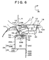
- the apron upper member upper 26 is formed with a U shaped cross section whose open portion faces downward, and tongue shaped pieces 54 serving as second deforming portions are formed at predetermined intervals in the vehicle longitudinal direction in the top wall portion 26E of the apron upper member upper 26.
- Mounting holes 56 are formed in the vicinity of a base portion 54A of the tongue piece 54, which is the inner side in the vehicle transverse direction.
- Nuts 58 serving as mounting members are fixed coaxially with the mounting holes 56 to the bottom surface of the tongue shaped pieces 54.
- Notches 60 cut in a V shape from both the front and rear directions of the vehicle are formed in the center portion in the vehicle transverse direction of the tongue shaped pieces 54, thereby forming weakened portions 54B.
- the end portions on the outer side in the vehicle transverse direction of the tongue shaped pieces 54 are supported from below by supporting pieces 62 serving as deformation control portions.
- the supporting pieces 62 are formed by being cut and then folded inside notches 64 formed in the outer wall portion 26A in the vehicle transverse direction of the apron upper member upper 26
- Tongue shaped pieces 66 serving as first deforming members are also formed protruding at predetermined intervals in the vehicle longitudinal direction in the sloping wall portion 14B of the fender 14.
- a mounting hole 68 is formed in a bottom end portion 66A of the tongue shaped pieces 66.
- each tongue shaped piece 66 in the fender 14 is fixed to the tongue shaped piece 54 of each apron upper member upper 26 by the bolt 70 and nut 58.
- the vertical width H of the sloping wall portion 14B of the fender 14 is narrowed in areas other than the tongue shaped pieces 66 so that there is hardly any interference thereby with the apron upper member 24.
- the bottom end portion 66A of the tongue shaped piece 66 of the fender 14 is fixed to the tongue shaped piece 54 of the apron upper member upper 26 by the nut 58 and bolt 70 and the outer end portion in the vehicle transverse direction of the tongue shaped piece 54 is supported from below by the supporting piece 62 serving as a deformation control member.
- the fender 14 can be reliably supported.
- a load above a predetermined value acts substantially from an upward direction in substantially a downward direction (i.e. in the direction shown by the arrow A in Fig. 6) on the boundary 16 between the hood panel 12 and the fender 14, the area in the vicinity of the boundary 16 of the hood panel 12 and the area in the vicinity of the boundary 16 of the fender 14 is deformed downward, as is shown by the double dot chain line in Fig. 6.
- the tongue shaped piece 54 serving as the second deforming portion of the apron upper member 24 buckles in a V shape with the weakened portion 54 B in which the V shaped notch 60 is formed as a base point and is deformed downward away from the supporting piece 62.
- the tongue shaped piece 66 serving as the first deforming portion of the fender 14 is also buckled. Therefore, because it is possible by the deformation of both the tongue shaped piece 54 and the tongue shaped piece 66 to absorb the impact energy, it is possible to reduce the amount of buckling deformation of the fender 14 generated by the impact load. As a result, because it is possible to absorb the impact energy within the range in which buckling deformation is possible of the fender 14, it is possible to obtain a low deformation load until the end of the deformation and the performance to mitigate the impact force is improved.
- the weakened portion 54B which acts as a trigger allowing the tongue shaped piece 54 to be deformed is provided, the deformation of the tongue shaped piece 54 can be further accelerated and the performance to mitigate the impact force is further improved.
- both the tongue shaped piece 54 and the tongue shaped piece 66 are deformed inside the closed cross section portion 30, it is possible to prevent the deformed tongue shaped piece 54 and the deformed tongue shaped piece 66 from interfering with adjacent members and the overall structure can be made more compact.
- the first deforming portion is formed from the tongue shaped piece 66 and the second deforming portion is formed from the tongue shaped piece 54, and because the deformation control portion is formed from the supporting piece 62 provided beneath the tongue shaped piece 54, the structure is simple and easily manufactured.
- the tongue shaped piece 66 serving as the first deforming member is formed integrally with the fender 14, however, instead of this, as is shown in Fig. 8, it is also possible to fix a tongue shaped piece 66 that has been formed as a separate member to the fender 14.
- the weakened portion 54B is formed using a V shaped notch 60, however, instead of the V shaped notch, it is also possible to form the weakened portion 54B by another weakened portion forming means, such as by using a thinned portion or the like.
- a concave groove 80 serving as a weakened portion that becomes the base point of deformation due to an impact load from substantially an upward direction on the vehicle outer surface 14F of the fender 14, is provided extending in the vehicle longitudinal direction.
- An ornamental molding 82 is attached to the concave groove 80.
- Flanges 84A and 84b of a bracket 84 serving as a connecting member are fixed to a bottom portion 80A of the concave groove 80.
- the bracket 84 is provided extending toward the inner side in the vehicle transverse direction and mounting holes 86 are punched in the inner end portion 84C in the vehicle transverse direction of the bracket 84.
- a notch 88 is formed in the sloping wall portion 14B of the fender 14 so that it does not interfere with the bracket 84.
- Mounting holes 90 are formed at predetermined intervals in the vehicle longitudinal direction in the top wall portion 26E of the apron upper member upper 26, and nuts 92 serving as mounting members are fixed coaxially with the mounting holes 90 to the bottom surface of the top wall portion 26E.
- the bottom portion 80A of the concave groove 80 of the fender 14 is fixed via the bracket 84 to the top wall portion 26E of the apron upper member upper 26. Therefore, the fender 14 can be reliably supported.
- a load of a predetermined value or more acts substantially from an upward direction in substantially a downward direction (i.e. in the direction shown by the arrow A in Fig. 9) on the boundary 16 between the hood panel 12 and the fender 14, the area in the vicinity of the boundary 16 of the hood panel 12 and the area in the vicinity of the boundary 16 of the fender 14 are deformed downward, as is shown by the double dot chain line in Fig. 9.
- the fender 14 is deformed with the concave groove 80 serving as the weakened portion in the vehicle outer surface 14F as a base point, and the bottom end portion of the sloping wall 14B of the fender 14 slides over the top of the top wall portion 26E of the apron upper member upper 26 toward the inner side in the vehicle transverse direction.
- the bracket 84 serving as a connecting member becomes a support pillar and the concave groove 80 of the fender 14 definitely becomes the base point of the deformation, it is possible to reduce the amount of buckling deformation of the fender 14 generated by the impact load.
- it is possible to absorb the impact energy within the range in which buckling deformation is possible of the fender 14 it is possible to obtain a low deformation load until the end of the deformation and the performance to mitigate the impact force is improved.
- the concave groove 80 which becomes the base point of the deformation of the fender 14 extends in the vehicle longitudinal direction, it is possible to improve the performance to mitigate the impact force across the entire longitudinal length of the vehicle.
- the concave groove 80 can double as a concave groove 80 for attaching the ornamental molding 82 and as the weakened portion which becomes the base point of the deformation of the fender 14.
- the arrow FR shows the direction of the front of the vehicle
- the arrow UP shows the direction of the top of the vehicle
- the arrow IN shows the direction of the inside of the vehicle.
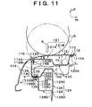
- the boundary 116 between a hood panel 112 and a fender 114 of a vehicle body 110 extends in the longitudinal direction of the vehicle at both end portions in the transverse direction of the vehicle of a front hood 118.
- the boundary 116 is set at the outer side in the vehicle transverse direction and, as is shown in Fig. 11, is structured so that it is difficult for a colliding body S to collide with the fender 114.
- the hood 118 is fixed to the vehicle body by left and right side hinges placed toward the rear of the vehicle body and a lock portion placed in the center of the hood 118 toward the front of the vehicle, and the hood 118 is elastically deformable around the fulcrums of the hinges and lock.
- a hood inner panel 120 is provided extending in the vehicle longitudinal direction at the bottom surface side of the outer side portions in the vehicle transverse direction of the hood panel (also known as the hood outer panel) 112.
- the cross sectional configuration of the hood inner panel 120 as seen from the vehicle longitudinal direction is formed generally in a hat shape with the open portion thereof facing upward.
- An inner flange 120A formed protruding outward at the inner side in the vehicle transverse direction of the open portion is joined to a bottom surface 112A of the hood panel 112 by an adhesive 113.
- a flange portion 120B is formed hanging downward at the outer end portion in the vehicle transverse direction of the open portion of the hood inner panel 120.
- This flange portion 120B is joined to a flange portion 112B formed hanging downward at the outer edge portion in the vehicle transverse direction of the hood panel 112, and the joined flange portions 120B and 112B form a rigidity ensuring means.
- a thickness T1 of the outer portion 121A in the vehicle transverse direction is thinner than a thickness T2 of the inner portion 121B in the vehicle transverse direction forming the framework portion of the hood 118.
- An apron upper member 124 which serves as a structural member of the vehicle body 110 in the vehicle longitudinal direction is provided below the outer portion 121A in the vehicle transverse direction of the closed cross section portion 121.
- the apron upper member 124 is formed from an apron upper member upper 126, which forms the top portion of the apron upper member 124, and an apron upper member lower 128, which forms the bottom portion of the apron upper member 124.
- the apron upper member upper 126 is formed with a trapezoid shaped cross section whose open portion faces downward and the outer wall portion 126A in the vehicle transverse direction is formed as a sloping surface that slopes from the vehicle inner side at the top to the vehicle outer side at the bottom.
- a flange 126B is formed toward the outer side in the vehicle transverse direction at the bottom end portion of the outer wall portion 126A in the vehicle transverse direction.
- the apron upper member lower 128 is formed with an L shaped cross section and a flange 128B, which is directed toward the outer side in the vehicle transverse direction, is formed at the top end portion of the vertical wall portion 128A.
- a horizontal wall portion 128C is formed toward the inner side in the vehicle transverse direction at the top end portion of the vertical wall portion 128A of the apron upper member lower 28, and a flange 128D is formed downward at the inner end portion in the vehicle transverse direction of the horizontal wall portion 128C.
- the bottom end edge portion 126D of the inner wall portion 126C in the vehicle transverse direction of the apron upper member upper 126 is welded to the flange 128D.
- the apron upper member 124 forms a closed cross section portion 130 that extends in the vehicle longitudinal direction through the apron upper member upper 126 and the apron upper member lower 128.
- mounting holes 132 are formed at predetermined intervals in the vehicle longitudinal direction in the joint portion of the flange 126B of the apron upper member upper 126 and the flange 128B of the apron upper member lower 128. Nuts 134 are fixed coaxially with the mounting holes 132 to the bottom surface of the flange 128B of the apron upper member lower 128.
- the inner edge portion 114A in the vehicle transverse direction of the fender 114 facing an outer edge portion 112C in the vehicle transverse direction of the hood panel 112 is bent downward, and a vertical wall portion 114B is formed extending substantially in parallel with the flange portion 112B of the hood panel 112.
- a flange 114C is formed toward the inner side in the vehicle transverse direction at the bottom end portion of the vertical wall portion 114B.
- mounting holes 136 are punched at predetermined intervals in the vehicle longitudinal direction in the flange 114C of the fender 114.
- a bolt 138 is inserted from above into each mounting hole 136 in the fender 114 and each mounting hole 132 in the apron upper member 124 and by fastening the bolt 138 to the nut 134, the flange 114C of the fender 114 is fixed to the flange 126B of the apron upper member upper 126 and the flange 128B of the apron upper member lower 128.
- a height H1 in the vertical direction of the vehicle of the flange 114C which becomes the mounting portion where the fender 114 is mounted on the apron upper member 124 is lower than a height H2 in the vehicle vertical direction of the top surface of the top wall portion 126E of the apron upper member upper 126.
- the outer portion 121A i.e. the hood portion that is thinner in the vehicle vertical direction than the inner side portion 121B in the vehicle transverse direction that forms the framework portion of the hood 118
- the vehicle transverse direction of the closed cross section portion 121 which is formed from the hood panel 112 and the hood inner panel 120 is provided above the top wall portion 126E of the apron upper member upper 126.
- the height H1 in the vertical direction of the vehicle of the flange 114C of the fender 114 is lower than the height H2 in the vehicle vertical direction of the top surface of the top wall portion 126E of the apron upper member upper 126, and the outer portion 121A in the vehicle transverse direction of the closed cross section portion 121 that is formed with a thin thickness is provided above the top wall portion 126E of the apron upper member upper 126.
- the flange portions 112B and 120B which serve as rigidity ensuring means, that are formed at the endpoint on the vehicle outer side of the hood 118.
- the rigidity ensuring means from the flange portions 112B and 120B that are formed hanging down from the endpoints on the vehicle outer side of the hood 118, the structure is simplified.
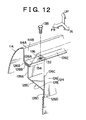
- convex ribs 150 protruding toward the inner side of the vehicle are formed at predetermined intervals in the vehicle longitudinal direction in the vertical wall portion 114B, which is the inner side wall portion in the vehicle transverse direction of the fender 114, at positions other than the area where bolts 138 are inserted.
- the convex ribs 150 are formed substantially in a triangle shape as seen from the vehicle longitudinal direction, and an upper sloping surfaces 150A thereof are positioned below the flange portions 112B and 120B that are formed hanging down from the endpoints on the vehicle outer side of the hood 118.
- the concave groove 152 serving as a weakened portion that becomes the base point for deformation at a vehicle outer side surface 114D of the fender 114 is provided extending in the vehicle longitudinal direction and ornamental moldings 154 are attached to the concave grooves 152.
- the height H1 in the vertical direction of the vehicle of the flange 114C of the fender 114 is lower than the height H2 in the vehicle vertical direction of the top surface of the top wall portion 126E of the apron upper member upper 126.
- the outer portion 121A in the vehicle transverse direction of the closed cross section portion 121 that is formed with a thin thickness is provided above the top wall portion 126E of the apron upper member upper 126.
- the angle of the slope ⁇ of the sloping surface 150A of the convex ribs 150 is made small, it is possible to lessen the effects on the deformation load of the hood 118 from the hood 118 abutting against the fender 114 because of the relationship between the component force in the horizontal direction and the component force in the vertical direction.
- the transverse width W1 of the hood 118 is large in this embodiment, it is possible to make the transverse width W2 of the fender 114 relatively smaller. Therefore, for this reason as well, the fender 114 is able to deform easily in the vehicle outer side direction as is shown by the chain line in Fig. 14.
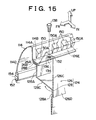
- an auxiliary framework portion 121C whose thickness T3 in the vehicle vertical direction is thicker than the thickness T1 of the outer portion 121A in the vehicle transverse direction is formed at the vehicle outer side of the outer portion 121A in the vehicle transverse direction of the closed cross section portion 121 that is formed from the hood panel 112 and the hood inner panel 120.
- This auxiliary framework portion 121C forms a rigidity ensuring means.
- the outer peripheral edge 112D in the vehicle transverse direction of the hood panel 112 is fixed by a hemming process to an outer flange 120C formed protruding outward at the outer side in the vehicle transverse direction of the open portion of the hood inner panel 120, and a hemmed portion 118A is formed running around the outline of the hood 118.
- a sloping surface 114E that slopes from the vehicle outer side at the top to the vehicle inner side at the bottom is formed in the area between the vertical wall portion 114B and the inner edge portion 114A in the vehicle transverse direction, which becomes the inner wall portion in the vehicle transverse direction of the fender 114.
- the position of the vertical wall portion 114b is shifted by a distance S toward the vehicle outer side relative to the auxiliary framework 121C. Accordingly, when the fender 114 is moved downward, the hemmed portion 118A is made to abut against the sloping surface 114E.
- the height H1 in the vertical direction of the vehicle of the flange 114C of the fender 114 is lower than the height H2 in the vehicle vertical direction of the top surface of the top wall portion 126E of the apron upper member upper 126.
- the outer portion 121A in the vehicle transverse direction of the closed cross section portion 121 that is formed with a thin thickness is provided above the top wall portion 126E of the apron upper member upper 126.
- auxiliary framework portion 121C whose thickness T3 in the vehicle vertical direction is thicker than the thickness T1 of the outer portion 121A in the vehicle transverse direction of the closed cross section portion 121 at the endpoint of the hood 118 in the direction of the vehicle outer side, it is possible to ensure the rigidity for holding the shape necessary in the endpoint of the hood 118 in the direction of the vehicle outer side.
- the endpoint of the hood 118 in the direction of the vehicle outer side is moved in a downward direction by a predetermined value or more, the hemmed portion 118A of the hood 118 abuts against the sloping surface 114E of the fender 114 and the hemmed portion 118A is easily deformed in the manner shown by the double dot chain line in Fig. 16. Accordingly, in this embodiment, it is possible to achieve a further reduction in the impact load through the deformation of the hemmed portion 118A.
- the sloping surface 114E that slopes from the vehicle outer side at the top to the vehicle inner side at the bottom is formed between the vertical wall portion 114B and the inner edge portion 114A in the vehicle transverse direction of the fender 114 in consideration of the constraints of the molding shape and the like in the manufacturing process.
- the arrow FR shows the direction of the front of the vehicle
- the arrow UP shows the direction of the top of the vehicle
- the arrow IN shows the direction of the inside of the vehicle.
- a boundary 216 between a hood panel 212 and the fender of a vehicle body 210 extends in the longitudinal direction of the vehicle at both end portions in the transverse direction of the vehicle of a hood 218.
- a hood inner panel 220 is provided extending in the vehicle longitudinal direction at the bottom surface of the outer portions in the vehicle transverse direction of the hood panel (also known as the hood outer panel) 212.
- the cross sectional shape of the hood inner panel 220 as seen from the vehicle longitudinal direction is formed substantially in a hat shape with the open portion thereof facing upward.
- An inner flange (not illustrated) formed protruding outward at the inner side in the vehicle transverse direction of the open portion is joined to the bottom surface 212A of the hood panel 212.
- An outer peripheral edge 212B of the hood panel 212 in the vehicle transverse direction is fixed by a hemming process to an outer flange 220A formed protruding outward at the outer side in the vehicle transverse direction of the open portion of the hood inner panel 220.
- a closed cross section portion 221 formed from the hood panel 212 and the hood inner panel 220 forms the framework of the hood panel 212.
- An apron upper member 224 which serves as a structural member of the vehicle body 210 is provided in the vehicle longitudinal direction below the hemmed portion 218A of the hood 218.
- An apron upper member 224 is formed from an apron upper member upper 226, which forms the top portion of the apron upper member 224, and an apron upper member lower 228, which forms the bottom portion of the apron upper member 224.
- the apron upper member upper 226 is formed with a trapezoid shaped cross section whose open portion faces downward and the top portion of the outer wall portion in the vehicle transverse direction is formed as a sloping wall portion 226A that slopes from the vehicle inner side at the top to the vehicle outer side at the bottom.
- the bottom portion of the outer wall portion in the vehicle transverse direction of the apron upper member upper 226 is formed as a vertical wall portion 226B.
- a flange 226C which is directed toward the outer side in the vehicle transverse direction, is formed at the bottom end portion of the vertical wall portion 226B.
- the apron upper member lower 228 is formed with an L shaped cross section and an outer end portion 228B in the vehicle transverse direction of a horizontal wall portion 228A and the flange 226C of the apron upper member upper 226 are welded together.
- a vertical wall portion 228C is formed downward at the inner end portion in the vehicle transverse direction of the horizontal wall portion 228A of the apron upper member lower 228.
- a bottom end edge portion 226E of the inner wall portion 226D in the vehicle transverse direction of the apron upper member upper 226 is welded to the vertical wall portion 228C.
- the apron upper member 224 forms a closed cross sectional portion 230 that extends in the vehicle longitudinal direction through the apron upper member upper 226 and the apron upper member lower 228.
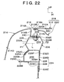
- brackets 232 serving as component force generating means are provided at predetermined intervals in the vehicle longitudinal direction on the apron upper member upper 226.
- the fender 214 is fixed to the apron upper member upper 226 via the brackets 232.
- the brackets 232 are formed with a substantially hexagonal cross section whose open portion faces downward when seen from the front of the vehicle (i.e. in front elevational view) and are provided with two linking wall portions 232A and 232B that face each other in the vehicle transverse direction (are offset in the vehicle transverse direction).
- the linking wall portion 232A on the outer side in the vehicle transverse direction (referred to hereafter as the outer linking wall portion) is bent in a V shape protruding toward the outer side in the vehicle transverse direction when seen from the front of the vehicle.
- the bend point P1 thereof is set above the center L in the vertical direction of the outer linking wall portion 232A.
- the linking wall portion 232B on the inner side in the vehicle transverse direction (referred to hereafter as the inner linking wall portion) is bent in a V shape protruding toward the inner side in the vehicle transverse direction when seen from the front of the vehicle.
- the bend point P2 thereof is set below the center L in the vertical direction of the inner linking wall portion 232B.
- a flange 232C is formed at the bottom end portion of the outer linking wall portion 232A of the bracket 232 and this flange 232C is welded to the sloping wall portion 226A of the apron upper member upper 226.
- a flange 232D is formed at the bottom end portion of the inner linking wall portion 232B of the bracket 232 and this flange 232D is welded to the top end edge portion 226F of the inner wall portion 226D in the vehicle transverse direction of the apron upper member upper 226.
- the top end portion of the outer linking wall portion 232A of the bracket 232 is linked by the top wall portion 232E to the top end portion of the inner linking wall portion 232B.
- Mounting holes 234 are punched in the center portion of this top wall portion 232E and weld nuts 236 are provided coaxially with the mounting holes 234 on the bottom surface of the top wall portion 232.
- An inner edge portion 214A in the vehicle transverse direction of the fender 214 that faces a hemmed portion 218A of the hood 218 is bent downward thereby forming a vertical wall portion 214B that extends in a vertical direction.
- a flange 214C is formed facing inward in the vehicle transverse direction at the bottom end portion of this vertical wall portion 214B and mounting holes 238 are punched at predetermined intervals in the vehicle longitudinal direction in the flange 214C.
- Bolts 240 are inserted from above into the mounting holes 234 of the bracket 232 and the mounting holes 238 of the fender 214. By fastening these bolts 240 with nuts 236, the flange 214C of the fender 214 is fixed to the top wall portion 232E of the bracket 232.
- a concave groove 242 is formed extending in the vehicle longitudinal direction in a vehicle outer side surface 214D of the fender 214 and an ornamental molding 244 is attached to the concave groove 242.
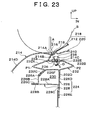
- the vehicle body is structured such that when a colliding body S collides with the boundary 216 between the hood 218 and the fender 214, and a load acts from a substantially upward direction in a substantially downward direction (i.e. in the direction indicated by the arrow A in Fig.
- the vehicle outer side surface 214D of the fender 214 easily deforms using the concave groove 242 as the base point and it is difficult for the deformation load to become large.
- the concave groove 242 is not formed in the vehicle outer side surface 214D of the fender 214, it is still possible to structure the vehicle body such that when a colliding body S collides with the boundary 216 between the hood 218 and the fender 214, and a load acts from a substantially upward direction in a substantially downward direction (i.e. in the direction indicated by the arrow A in Fig.
- the fender 214 due to other factors such as the material used to construct the fender 214, the configuration (i.e. curvature or inclination) of the vehicle outer side surface 214D, the way the fender 214 is mounted, and the like, the fender 214 easily deforms and it is difficult for the deformation load to increase when there is a large amount of deformation of the fender 214.
- the outer linking wall portion 232A of the bracket 232 that fixes the fender 214 to the apron upper member upper 226 is bent in a V shape protruding toward the outer side in the vehicle transverse direction when seen from front of the vehicle.
- the bend point P1 thereof is set above the center L in the vertical direction of the outer linking wall portion 232A, while the inner linking wall portion 232B is bent in a V shape protruding toward the inner side in the vehicle transverse direction when seen from front of the vehicle.
- the bend point P2 thereof is set below the center L in the vertical direction of the inner linking wall portion 232B. Therefore, as is shown in Fig.
- the outer linking wall portion 232A and the inner linking wall portion 232B are each deformed by the component forces distributed to the outer linking wall portion 232A and the inner linking wall portion 232B.
- the top wall portion 232E of the bracket 232 together with the flange 214C of the fender 214 is crushed in a downward direction toward the outer side in the vehicle transverse direction (i.e. in the direction shown by the arrow B in Fig. 19).
- the outer linking wall portion 232A of the bracket 232 is bent in a V shape protruding toward the outer side in the vehicle transverse direction when seen from the front of the vehicle.
- the bend point P1 thereof is set below the center L in the vertical direction of the outer linking wall portion 232A.
- the inner linking wall portion 232B is bent in a V shape protruding toward the inner side in the vehicle transverse direction when seen from the front of the vehicle.
- the bend point P2 thereof is set above the center L in the vertical direction of the inner linking wall portion 232B.
- the vehicle body is structured such that when a load acts from a substantially upward direction in a substantially downward direction (i.e. in the direction shown by the arrow B in Fig. 19), and if there is a large amount of deformation in the fender 214, it is easy that the deformation load increases.
- the concave groove is formed in the vehicle outer side surface 214D of the fender 214, it is still possible to structure the vehicle body such that when a colliding body S collides with the boundary 216 between the hood 218 and the fender 214, and a load acts from a substantially upward direction in a substantially downward direction (i.e. in the direction indicated by the arrow A in Fig. 23), due to other factors such as the material used to construct the fender 214, the configuration (i.e. curvature or inclination) of the vehicle outer side surface 214D, the way the fender 214 is mounted, and the like, it is easy for the deformation load to decrease when there is a large amount of deformation of the fender 214.
- the outer linking wall portion 232A of the bracket 232 that fixes the fender 214 to the apron upper member upper 226 is bent in a V shape protruding toward the outer side in the vehicle transverse direction when seen from the front of the vehicle and the bend point P1 thereof is set below the center L in the vertical direction of the outer linking wall portion 232A, while the inner linking wall portion 232B is bent in a V shape protruding toward the inner side in the vehicle transverse direction when seen from the front of the vehicle.
- the bend point P2 thereof is set above the center L in the vertical direction of the inner linking wall portion 232B. Therefore, as is shown in Fig.
- the outer linking wall portion 232A and the inner linking wall portion 232B are each deformed by the component forces distributed to the outer linking wall portion 232A and the inner linking wall portion 232B.
- the top wall portion 232E of the bracket 232 together with the flange 214C of the fender 214 is crushed in a downward direction toward the inner side in the vehicle transverse direction (i.e. in the direction shown by the arrow D in Fig. 23).
- the hemmed portion 218A of the hood 218 which deforms toward the outer downward side in the vehicle transverse direction interferes with the fender 214
- using a simple structure it is possible to prevent curvature deformation of the vehicle outer side surface 214D of the fender 214 in the same manner as in the fifth embodiment (see Fig. 19).
- the vehicle outer side surface 214D of the fender 214 that has a large deformation load is not allowed to deform, it is possible to suppress increases in the deformation load of the fender 214 and to improve the performance to mitigate the impact force.
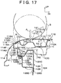
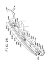
- the fender 214 is formed from a resin material and two linking wall portions 214E and 214F that serve as component force generating means are formed integrally with the fender 214 facing each other in the vehicle transverse direction.
- the linking wall portion 214E on the outer side in the vehicle transverse direction (referred to hereafter as the outer linking wall portion) is bent in a V shape protruding toward the outer side in the vehicle transverse direction when seen from the front of the vehicle and the bend point P1 thereof is set above the center L in the vertical direction of the outer linking wall portion.
- the linking wall portion 214F on the inner side in the vehicle transverse direction (referred to hereafter as the inner linking wall portion) is bent in a V shape protruding toward the inner side in the vehicle transverse direction when seen from the front of the vehicle and the bend point P2 thereof is set below the center L in the vertical direction of the inner linking wall portion 214F.
- the top portion of the outer linking wall portion 214E of the fender 214 is linked to the bottom end portion of the vertical wall portion 214B, while the top end portion of the inner linking wall portion 214F is linked to the inner end portion in the vehicle transverse direction of the top wall portion 214G extending inward in the vehicle transverse direction from the bottom end portion of the vertical wall portion 214B.
- the bottom end portion of the outer linking wall portion 214E and the bottom end portion of the inner linking wall portion 214F are linked by a bottom wall portion 214H.
- the bottom wall portion 214H, the inner linking wall portion 214F, and the outer linking wall portion 214E of the fender 214 are formed at predetermined intervals in the vehicle longitudinal direction. Moreover, the bottom wall portion 214H of the fender 214 is provided extending in the vehicle longitudinal direction forming the mounting portion 214J.
- mounting holes 250 are punched at predetermined intervals toward the front of the vehicle longitudinal direction in a top wall portion 226G of the apron upper member upper 226 and weld nuts 252 are provided coaxially with the mounting holes on the bottom surface of the top wall portion 226G.
- mounting holes 254 are punched in the center portion of the mounting portion 214J of the fender 214.
- the mounting portion 214J of the fender 214 is fixed to the top wall portion 226G of the apron upper member upper 226.
- the vehicle body is structured such that when a colliding body S collides with the boundary 216 of the hood 218 and the fender 214 and a load acts substantially from an upward direction in substantially a downward direction (i.e. in the direction shown by the arrow A in Fig. 25), even if the amount of deformation of the fender 214 is great, it is difficult for the deformation load to increase.
- a colliding body S collides with the boundary 216 of the hood 218 and the fender 214 and a load acts substantially from an upward direction in substantially a downward direction (i.e. in the direction shown by the arrow A in Fig. 25)
- the area in the vicinity of the boundary 216 of the hood panel 212 and the area in the vicinity of the boundary 216 of the fender 214 is deformed downward as is shown in Fig. 25.
- the outer linking wall portion 214E formed integrally with the fender 214 that fixes the fender 214 to the apron upper member upper 226 is bent in a V shape protruding toward the outer side in the vehicle transverse direction when seen from the front of the vehicle and the bend point P1 thereof is set above the center L in the vertical direction of the outer linking wall portion 214E, while the inner linking wall portion 214F is bent in a V shape protruding toward the inner side in the vehicle transverse direction when seen from the front of the vehicle and the bend point P2 thereof is set below the center in the vertical direction of the inner linking wall portion 214F. Therefore, as is shown in Fig.
- the outer linking wall portion 214E and the inner linking wall portion 214F are each deformed by the component forces distributed to the outer linking wall portion 214E and the inner linking wall portion 214F.
- the bottom end portion of the vertical wall portion 214B of the fender 214 is crushed in a downward direction toward the outer side in the vehicle transverse direction (i.e. in the direction shown by the arrow B in Fig. 25).
- the number of parts can be decreased and the ease of assembly thereby improved.
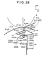
- the fender 214 is formed from a resin material and two linking wall portions 214E and 214F that serve as component force generating means are formed integrally facing each other in the vehicle transverse direction.
- the outer linking wall portion 214E is bent in a V shape protruding toward the outer side in the vehicle transverse direction when seen from the front of the vehicle and the bend point P1 thereof is set below the center L in the vertical direction of the outer linking wall portion.
- the inner linking wall portion 214F is bent in a V shape protruding toward the inner side in the vehicle transverse direction when seen from the front of the vehicle and the bend point P2 thereof is set above the center L in the vertical direction of the inner linking wall portion 214F.
- the outer linking wall portion 214E formed integrally with the fender 214 that fixes the fender 214 to the apron upper member upper 226 is bent in a V shape protruding toward the outer side in the vehicle transverse direction when seen from the front of the vehicle and the bend point P1 thereof is set below the center L in the vertical direction of the outer linking wall portion 214E, while the inner linking wall portion 214F is bent in a V shape protruding toward the inner side in the vehicle transverse direction when seen from the front of the vehicle and the bend point P2 thereof is set above the center in the vertical direction of the inner linking wall portion 214F. Therefore, as is shown in Fig.
- the outer linking wall portion 214E and the inner linking wall portion 214F are each deformed by the component forces distributed to the outer linking wall portion 214E and the inner linking wall portion 214F.
- the bottom end portion of the vertical wall portion 214B of the fender 214 is crushed in a downward direction toward the inner side in the vehicle transverse direction (i.e. in the direction shown by the arrow D in Fig. 28).
- the hemmed portion 218A of the hood 218 which deforms toward the outer downward side in the vehicle transverse direction interferes with the fender 214
- using a simple structure it is possible to prevent curvature deformation of the vehicle outer side surface 214D of the fender 214 that occurs in the tenth embodiment (see Fig. 25).
- the vehicle outer side surface 214D of the fender 214 that has a large deformation load is not allowed to deform, it is possible to suppress increases in the deformation load of the fender 214 and to improve the performance to mitigate the impact force.
- the number of parts can be decreased and the ease of assembly thereby improved in the same way as in the tenth embodiment.
- the fender 214 is formed from a resin material and two linking wall portions 214E and 214F that serve as component force generating means are formed integrally with the fender 214, however, instead of this, it is also possible to form the fender 214 from another material such as a metal cast using a light alloy such as aluminum and to form the linking wall portions 214E and 214F that serve as component force generating means integrally with the fender 214.
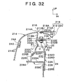
- the outer linking wall portion and the inner linking wall portion that face each other are both formed in a V shape, however, instead of this, as is shown in Fig. 31, it is also possible to form just one of the outer linking wall portion 232A and the inner linking wall portion 232B bent in a V shape (in Fig. 31, this is the inner linking wall portion 232B).
- the outer linking wall portion is bent in a V shape protruding toward the outer side in the vehicle transverse direction as seen from the front of the vehicle
- the inner linking wall portion is bent in a V shape protruding toward the inner side in the vehicle transverse direction as seen from the front of the vehicle.
- the outer linking wall portion 232A is bent in a V shape protruding toward the inner side in the vehicle transverse direction as seen from the front of the vehicle
- the inner linking wall portion 232B is bent in a V shape protruding toward the outer side in the vehicle transverse direction as seen from the front of the vehicle.
- the outer linking wall portion is bent in a V shape protruding toward the outer side in the vehicle transverse direction as seen from the front of the vehicle
- the inner linking wall portion is bent in a V shape protruding toward the inner side in the vehicle transverse direction as seen from the front of the vehicle.
- a structure in which both the inner linking wall portion 232B and the outer linking wall portion 232A are bent in a V shape protruding in the same direction as seen from the front of the vehicle in Fig. 34, this is toward the outer side in the vehicle transverse direction).
- the direction in which the fender 214 crushes i.e. the direction indicated by the arrow B in Fig. 34
- the direction of the V shaped bend in Fig. 34, this is the outward direction in the vehicle transverse direction.
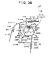
- At least one of the inner linking wall portion and the outer linking wall portion is bent in a V shape at one bend point in the vertical direction, however, instead of this, as is shown in Fig. 35, it is also possible to employ a structure in which at least one of the outer linking wall 232A and the inner linking wall 232B is bent at a plurality of bend points P1 and P3 as well as P2 and P4 in the vertical direction.
- At least one of the outer linking wall portion and the inner linking wall portion is bent at a bend point.
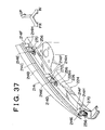
- the bottom wall portion 214H of the fender 214 is formed as the mounting portion 214J extending in the vehicle forward direction, however, instead of this, as is shown in Fig. 37, it is also possible to employ a structure in which the bottom wall portion 214H of the fender 214 is held by a press plate 270 formed as a separate member and fixed by the bolt 256 to the top wall portion 226G of the apron upper member upper 226.
- the component force generating means is formed from the two outer linking wall portions 232A and 214E and inner linking wall portions 232B and 214F that face each other in the vehicle transverse direction.
- the arrow FR shows the direction of the front of the vehicle
- the arrow UP shows the direction of the top of the vehicle
- the arrow IN shows the direction of the inside of the vehicle.
- a boundary 316 between a hood 312 of a vehicle body 310 and a fender panel 314 that is formed from metal or resin extends in the longitudinal direction of the vehicle at both end portions in the transverse direction of the vehicle of a front hood 318.
- a hood inner panel 320 is provided extending in the vehicle longitudinal direction at the bottom surface of the outer portions in the vehicle transverse direction of the hood panel (also known as the hood outer panel) 312.
- the cross sectional configuration of the hood inner panel 320 as seen from the vehicle longitudinal direction is formed generally in a hat shape with the open portion thereof facing upward.
- An inner flange 320A formed protruding outward at the inner side in the vehicle transverse direction of the open portion is joined with adhesive to a bottom surface 312A of the hood panel 312.
- An outer peripheral edge 312B in the vehicle transverse direction of the hood panel 312 is fixed by a hemming process to an outer flange 320B formed protruding outward at the outer side in the vehicle transverse direction of the open portion of the hood inner panel 320.
- a closed cross section portion 321 formed from the hood panel 312 and the hood inner panel 320 forms the framework of the hood panel 312, and is also provided with load monodeformation characteristics capable of absorbing sufficient impact even if a colliding body S collides with only the hood panel 312.
- An apron upper member 324 which serves as a structural member of the vehicle body 310 is provided in the vehicle longitudinal direction below the boundary 316 of the hood panel 312 and the fender panel 314.
- the apron upper member 324 is formed from an apron upper member upper 326, which forms the top portion of the apron upper member 324, and an apron upper member lower 328, which forms the bottom portion of the apron upper member 324.
- the apron upper member upper 326 is formed with a U shaped cross section whose open portion faces downward and a flange 326B, which is directed toward the outer side in the vehicle transverse direction, is formed at the bottom end portion of the outer wall portion 326A in the vehicle transverse direction.
- the apron upper member lower 328 is formed with an L shaped cross section and a horizontal wall portion 328B, which is directed to the outer side in the vehicle transverse direction, is formed at the top end portion of the vertical wall portion 238A.
- the flange 326B of the apron upper member upper 326 and a distal end portion 328C of the horizontal wall portion 328B of the apron upper member lower 328 are welded together.
- the bottom end edge portion 326D of the inner wall portion 326C in the vehicle transverse direction of the apron upper member upper 326 is welded to the inner surface 328D in the vehicle transverse direction of the top end edge portion of the vertical wall portion 328A of the apron upper member lower 328.
- the apron upper member 324 forms a closed cross sectional portion 330 that extends in the vehicle longitudinal direction through the apron upper member upper 326 and the apron upper member lower 328.
- mounting holes 332 are formed spaced at predetermined intervals in the vehicle longitudinal direction in a top wall portion 326E of the apron upper member upper 326.
- an inner edge portion 314A in the vehicle transverse direction of the fender panel 314 that faces an outer edge portion 312B in the vehicle transverse direction of the hood panel 312 is formed as a parting portion of the fender panel 314.
- the inner edge portion 314A in the vehicle transverse direction curves downward and a narrow step portion 314F is formed facing the vehicle inner side at the bottom of this curved portion.
- a sloping wall portion 314B is provided extending in the vehicle transverse direction from the inner end P1 in the vehicle transverse direction of the step portion 314F toward the vicinity of the top wall portion 326E of the apron upper member upper 326 that is on the inner side in the vehicle transverse direction.
- a substantially horizontal flange portion 314C is formed extending inward in the vehicle transverse direction from the bottom end portion P2 of the sloping wall portion 314B.
- the flange portion 314C abuts against the top wall portion 326E of the apron upper member upper 326.
- mounting portions 314D of the fender panel 314 where the fender panel 314 is mounted to the apron upper member upper 326 are formed at predetermined intervals in the vehicle longitudinal direction and each mounting portion 314D is formed substantially horizontally.
- Mounting holes 334 are punched in the center portion of each mounting portion 314D and bolts 336 are inserted from the top into the mounting holes 334 and the mounting holes 332 in the apron upper member upper 326.
- the fender panel 314 is fixed to the apron upper member upper 326 by these bolts 336 and weld nuts 338 that are fixed to the bottom surface of the top wall portion 326E of the apron upper member upper 326.
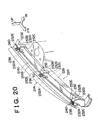
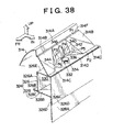
- folding portions 340, 342, and 344 which are folded by a load substantially from above, are formed between the mounting portions 314D and the sloping wall portions 314B of the fender panel 314.
- the folding portion 340 is provided at the outer side in the vehicle transverse direction of the mounting portion 314D and a bent portion P3 is formed protruding inward in the vehicle transverse direction in the center portion in the vertical direction of the folding portion 340.
- the cross section of the folding portion 340 is shaped in a V shape bending inward in the vehicle transverse direction when looked at from the vehicle longitudinal direction.
- the boundary between the mounting portion 314D and the bottom end portion of the folding portion 340 forms a bent portion P4.
- the lengths between the various portions are set as: S1 between P1 and P2; S2 between P1 and P3; S3 between P3 and P4; and S4 between P4 and P2, then these lengths have the relationship: S1 ⁇ S2 - S3 + S4.
- the distance in a direct line between the top end P1 and the bottom end P2 after folding is set so as to be substantially the same as the distance in a straight line between the top end P1 and the bottom end P2 before folding.
- An elongated hole portion 346 that cuts through the bent portion P3 is formed extending in the vehicle vertical direction in the center portion in the vehicle longitudinal direction of the folding portion 340.
- This hole portion 346 is designed so as to be compressed in the manner shown by the double dot chain line in Figs. 38 and 40 when the folding portion 340 becomes folded.
- the folding portion 342 is provided toward the vehicle rear on the mounting portion 314D and, when looked at in plan view, extends from the rear end of the folding portion 340 rearwards and inward in the vehicle transverse direction. Moreover, a bent portion P5 is formed protruding toward the inner forward side of the vehicle at the center portion in the vertical direction of the folding portion 342, and the cross section of the folding portion 342, as seen from the transverse direction of the vehicle, is formed in a V shape bent toward the front of the vehicle.
- a folding portion 344 is provided toward the vehicle front on the mounting portion 314D and, when looked at in plan view, extends from the front end of the folding portion 340 forwards and inward in the vehicle transverse direction. Moreover, a bent portion P6 is formed protruding toward the inner rearward side of the vehicle at the center portion in the vertical direction of the folding portion 344, and the cross section of the folding portion 344, as seen from the transverse direction of the vehicle, is formed in a V shape bent toward the rear of the vehicle.
- a recessed portion 348 is formed in the area opposing the folding portions 340, 342, and 344 in the top wall portion 326E of the apron upper member upper 326. As is shown in Fig. 41, when the folding portion 340 becomes folded, a portion of the folding portion 340 enters the recessed portion 348.
- the mounting portion 314D of the fender panel 314 is fixed to the top wall portion 326E of the apron upper member upper 326. Therefore, because the portion for mounting on the apron upper member upper 326 is not provided on a sloping wall portion as in the conventional structure, the engine room 371 is not made any smaller by protruding of the mounting portion 314D of the fender panel 314 toward the inner side in the vehicle transverse direction.
- a colliding body S collides with the boundary 16 between the hood panel 12 and the fender 14 and the load acts substantially from an upward direction in substantially a downward direction (i.e. in the direction shown by the arrow A in Fig. 38), the area in the vicinity of the boundary 16 of the hood panel 12 and the area in the vicinity of the boundary 16 of the fender 14 is deformed downward, as is shown by the double dot chain line in Fig. 41.
- the folding portions 340, 342, and 344 of the fender panel 314 are folded by an impact load from a substantially upward direction, for example, as is shown in Fig. 41, with the top end P1 of the folding portion 340 rotating toward the vehicle outer side about the bottom end P2 and the folding portion 340 thereby being folded resulting in the deformation load being reduced.
- the hole portion 346 provided in the folding portion 340 which is on the outer side in the vehicle transverse direction of the mounting portion 314D, as is shown by the double dot chain line in Fig.
- the lengths in the folding portion 340 between the various portions are set as: S1 between P1 and P2; S2 between P1 and P3; S3 between P3 and P4; and S4 between P4 and P2, then these lengths have the relationship: S1 ⁇ S2 - S3 + S4.
- the distance in a direct line between the top end P1 and the bottom end P2 after folding is set so as to be substantially the same as the distance in a straight line between the top end P1 and the bottom end P2 before folding. Therefore, when the folding portion 340 is folded, no new bent portion is created and the deformation load can be reliably reduced. Moreover, after the folding, it is possible to prevent the bent portion P4 from protruding downward too much.
- a portion (i.e. the bent portion P4) of the folding portion 340 enters the recessed portion 348. Accordingly, a portion of the folding portion 340 abuts against the apron upper member upper 326 and any further bending is prevented, therefore, the deformation load is further reduced.
- a large hole portion 360 is formed on the outer side in the vehicle transverse direction of the mounting portion 314D of the fender panel 314, and folding portions 342 and 344 are formed respectively in the vehicle rear side and vehicle front side of the hole portion 360, in the same way as in the twelfth embodiment.
- the mounting portion 314D of the fender panel 314 is fixed to the top wall portion 326E of the apron upper member upper 326. Therefore, because the portion for mounting on the apron upper member upper 326 is not provided on a sloping wall portion as in the conventional structure, the engine room 371 is not made any smaller by protruding of the mounting portion 314D of the fender panel 314 toward the inner side in the vehicle transverse direction.
- a large hole portion 364 is formed in the fender panel 314 and the mounting portion of the fender panel 314 is a mounting portion 366A of a bracket 366 which is a separate body.
- a mounting hole 332 for mounting on the apron upper member upper 326 is formed in the mounting portion 336A of the bracket 336, and the inner end portion 366B in the vehicle transverse direction of the mounting portion 366A is joined to the bottom surface of a joining portion 314E formed continuously with the flange 314C of the hood panel 314.
- a flange portion 366C is formed at the top end portion of the bracket 366 and the rear surface of the sloping wall portion 314B is joined to the flange portion 366C. Note that the flange portion 366C extends in the vehicle longitudinal direction and widened portions 366D are formed at both ends of the flange portion 366C in the vehicle longitudinal direction.
- the size of the hole 364 is set such that a jig for fastening the bolt 336 can be inserted therein, and a folding portion 368 that is folded by a load from a substantially upward direction is formed between the mounting portion 366A of the bracket 366 and the flange portion 366C of the bracket 366.
- the folding portion 368 is provided at the outer side in the vehicle transverse direction of the mounting portion 366A, and a bent portion P7 that protrudes outward in the vehicle transverse direction is formed at the center portion in the vertical direction of the folding portion 368.
- the cross section of the folding portion 368 as seen from the vehicle longitudinal direction is formed as a V shape bent outward in the vehicle transverse direction.
- a hole portion 372 and a hole portion 374 are formed respectively at the vehicle front side and vehicle rear side of the folding portion 368.
- the flange 314C of the fender panel 314 is fixed to the top wall portion 326E of the apron upper member upper 326. Therefore, because the portion for mounting on the apron upper member upper 326 is not provided on a sloping wall portion as in the conventional structure, the engine room 371 is not made any smaller by protruding of the mounting portion of the fender panel 314 toward the inner side in the vehicle transverse direction.
- the folding portion 368 and the mounting portion 366A are formed in the bracket 366 that is formed separately from the fender panel 314, it is possible to set the shape of the folding portion 368 without having to consider the formability of the fender panel 314. A result of this is that, for example, the degree of freedom in the design of the fender panel 314 is improved.
- the shape of the cross section of the folding portions 340, 342, 344, and 368 is not limited to a V and it is also possible to use a Z shape or the like.
- a sloping wall portion (14B) of a fender (14) and a sloping wall portion (26F) of an apron upper member upper (26) are sandwiched between a bottom piece portion (36A) and a top piece portion (36B) of a nut plate (36), resulting in the sloping wall portion (14B) of the fender (14) being fixed at the top portion (32B) of a hole (32) to the sloping wall portion (26F) of an apron upper member upper (26). Therefore, the fender (14) and both the nut plate (36) and bolt (38) are moved substantially downward by an impact load from a substantially upward direction relative to the apron upper member (24), as is shown by the double dot chain line.
Abstract
Description
Moreover, after the folding, it is possible to prevent the bent portion P4 from protruding downward too much.
Claims (28)
- A structure for a fender portion of a vehicle in which a fender is mounted on a structural member of a vehicle using a mounting member, characterized in that at least the fender from out of the fender and the mounting member is moved relatively to the structural member by an impact load from a substantially upward direction.
- The fender portion structure according to claim 1, wherein the mounting member comprises a nut plate and a fastening bolt, and a hole is formed in the structural member such that the mounting member is capable of being moved by an impact load from a substantially upward direction.
- The fender portion structure according to claim 1, wherein the mounting member comprises a nut that is fixed to the structural member and a fastening bolt, and a hole is formed in the fender such that the fender is capable of being moved relative to the mounting member by an impact load from a substantially upward direction.
- A structure for a fender portion of a vehicle in which a fender is mounted on a structural member of a vehicle, characterized in that the fender portion structure is provided with a first deforming portion in the fender that is deformed by an impact load from a substantially upward direction, a second deforming portion in the structural member that is deformed by an impact load from a substantially upward direction, and a deformation suppressing means that suppresses a deformation of the first deforming portion and the second deforming portion at a predetermined load or less.
- The fender portion structure according to claim 4, wherein the first deforming portion is a tongue shaped piece in the fender and the second deforming portion is a tongue shaped piece in the structural member, and the deformation suppressing means is a supporting piece provided below the tongue shape piece in the structural member.
- The fender portion structure according to claim 5, wherein the tongue shaped piece in the structural member is provided with a weakened portion that acts as a trigger for deformation.
- A structure for a fender portion of a vehicle in which a fender is mounted on a structural member of a vehicle, characterized in that the fender portion structure is provided with a weakened portion on an outside surface in the vehicle transverse direction of the fender that becomes a base point of deformation caused by an impact load from a substantially upward direction, and with a linking member that links the vicinity of the weakened portion with the structural member.
- The fender portion structure according to claim 7, wherein the weakened portion is a concave groove extending in the longitudinal direction of the vehicle.
- The fender portion structure according to claim 8, wherein an ornamental molding is attached to the concave groove.
- A structure for a fender portion of a vehicle in which a fender is mounted on a structural member of a vehicle, characterized in that a height in the vertical direction of the vehicle where the mounting portion of the fender is mounted on the structural member is set lower than a height in the vertical direction of the vehicle of a top surface of the structural member, and a portion that is thinner in the vertical direction of the vehicle than a framework of a hood is provided above the top surface of the structural member.
- The fender portion structure according to claim 10, wherein rigidity ensuring means is provided in an area of the hood facing the fender mounting portion.
- The fender portion structure according to claim 11, wherein the rigidity ensuring means is a flange portion that hangs down and is formed at an outer end in the vehicle transverse direction of the hood.
- The fender portion structure according to claim 11, wherein the rigidity ensuring means is a hood auxiliary framework that is formed at an outer side in the transverse direction of the vehicle of the thinly formed hood portion and whose thickness in the vertical direction of the vehicle is thicker than the thinly formed hood portion.
- The fender portion structure according to any one of claims 10 to 13, wherein the fender is provided with a sloping surface in an inner wall portion in the transverse direction of the vehicle that slopes from the outer side of the vehicle at the top to the inner side of the vehicle at the bottom.
- The fender portion structure according to any one of claims 10 to 13, wherein the fender is provided with a substantially triangular shaped convex rib in an inner wall portion in the transverse direction of the vehicle that runs toward an inner side in the vehicle transverse direction.
- A structure for a fender portion of a vehicle in which a fender is mounted on a structural member of a vehicle, characterized in that the structure is provided with component force generating means for separating force input into a fender from a substantially upward direction into plurality of component forces that are offset in the transverse direction of the vehicle and thus controlling a direction in which the fender is crushed.
- The fender portion structure according to claim 16, wherein the component force generating means comprises at least two linking wall portions that face each other in the transverse direction of the vehicle.
- The fender portion structure according to claim 17, wherein the linking wall portions are integral with the fender.
- The fender portion structure according to claim 17 or 18, wherein at least one of the linking wall portions is not formed rectilinearly as seen from the front of the vehicle.
- The fender portion structure according to claim 17 or 18, wherein, in the linking wall portions, two facing linking wall portions are not formed rectilinearly as seen from the front of the vehicle.
- The fender portion structure according to claim 20, wherein, in the linking wall portions, positions in the vertical direction of respective bend points of two facing linking wall portions are different from each other.
- The fender portion structure according to claim 20, wherein, in the linking wall portions, respective bending directions of two facing linking wall portions are different from each other in the transverse direction of the vehicle.
- A structure for a fender portion of a vehicle in which a fender is mounted on a structural member of a vehicle, characterized in that the structure is provided with a general surface between the structural member and a parting portion between a hood that is formed as a sloping wall portion that slopes downward toward the inner side in the vehicle transverse direction, a fender panel whose attachment portion to the structural member is substantially horizontal, and, between the sloping wall portion and the mounting portion, a folding portion that is folded by a load from a substantially upward direction and a hole that is contracted when the folding portion is folded.
- The fender portion structure according to claim 23, wherein the folding portions are provided at least to the front and rear in the longitudinal direction of the vehicle of the mounting portion, and the hole portion is provided at an outer side in the vehicle transverse direction of the mounting portion.
- The fender portion structure according to claim 24, wherein a straight line distance between a bottom end and a top end of the folding portion before it is folded is substantially equal to a straight line distance between a bottom end and a top end of the folding portion after it is folded.
- The fender portion structure according to claim 24 or 25, wherein a recessed portion is provided in an area opposite the folding portion of the structural member.
- The fender portion structure according to claim 23, wherein the folding portion is provided at an outer side in the vehicle transverse direction of the mounting portion, and the hole portions are provided to the front and rear in the longitudinal direction of the vehicle of the mounting portion.
- The fender portion structure according to claim 27, wherein the folding portion is formed separately from the fender panel.
Applications Claiming Priority (8)
| Application Number | Priority Date | Filing Date | Title |
|---|---|---|---|
| JP2000098312A JP4200632B2 (en) | 2000-03-31 | 2000-03-31 | Vehicle fender structure |
| JP2000096667A JP4250852B2 (en) | 2000-03-31 | 2000-03-31 | Vehicle fender structure |
| JP2000098312 | 2000-03-31 | ||
| JP2000096667 | 2000-03-31 | ||
| JP2000106242 | 2000-04-07 | ||
| JP2000106242A JP4122680B2 (en) | 2000-04-07 | 2000-04-07 | Vehicle fender structure |
| JP2000311571 | 2000-10-12 | ||
| JP2000311571A JP4140186B2 (en) | 2000-10-12 | 2000-10-12 | Vehicle fender structure |
Publications (3)
| Publication Number | Publication Date |
|---|---|
| EP1138579A2 true EP1138579A2 (en) | 2001-10-04 |
| EP1138579A3 EP1138579A3 (en) | 2003-12-17 |
| EP1138579B1 EP1138579B1 (en) | 2006-05-31 |
Family
ID=27481168
Family Applications (1)
| Application Number | Title | Priority Date | Filing Date |
|---|---|---|---|
| EP01108138A Expired - Lifetime EP1138579B1 (en) | 2000-03-31 | 2001-03-30 | Vehicle fender structure |
Country Status (5)
| Country | Link |
|---|---|
| EP (1) | EP1138579B1 (en) |
| KR (1) | KR100417942B1 (en) |
| CN (1) | CN1214940C (en) |
| AU (1) | AU757679B2 (en) |
| DE (1) | DE60120024T2 (en) |
Cited By (16)
| Publication number | Priority date | Publication date | Assignee | Title |
|---|---|---|---|---|
| EP1346887A1 (en) * | 2002-03-15 | 2003-09-24 | Nissan Motor Company, Limited | Fender structure |
| EP1398249A1 (en) * | 2002-09-13 | 2004-03-17 | Renault s.a.s. | Multi-purpose support for positioning and attaching a body part of a car |
| WO2004067322A2 (en) * | 2003-01-28 | 2004-08-12 | Magna Steyr Fahrzeugtechnik Ag & Co Kg | Front section of a motor vehicle |
| EP1484235A1 (en) * | 2003-06-03 | 2004-12-08 | Compagnie Plastic Omnium | Vehicle wing support |
| FR2855809A1 (en) * | 2003-06-03 | 2004-12-10 | Plastic Omnium Cie | Fender bracket for motor vehicle, has metallic bore with upper part including ribs arranged to stiffen and flash upper part, when fender bracket is mounted on vehicle, and having holes to satisfy pre-defined criteria |
| FR2860763A1 (en) * | 2003-10-13 | 2005-04-15 | Renault Sa | PRE-MOVING BODY ELEMENT FOR DAMPING A PIECE SHOCK |
| FR2870497A1 (en) * | 2004-05-19 | 2005-11-25 | Inoplast Sa | ELEMENT FORMING SUPPORT FOR A PART OF A MOTOR VEHICLE |
| DE102005012773A1 (en) * | 2005-03-19 | 2006-09-21 | Bayerische Motoren Werke Ag | Bump stop for a front door of a motor vehicle |
| WO2007058787A2 (en) * | 2005-11-14 | 2007-05-24 | General Electric Company | Energy absorbing vehicle fender |
| EP1920998A1 (en) * | 2006-11-10 | 2008-05-14 | GM Global Technology Operations, Inc. | Motor vehicle bodywork and assembly method therefor |
| DE102008010138A1 (en) * | 2008-02-20 | 2009-08-27 | Dr. Ing. H.C. F. Porsche Aktiengesellschaft | mudguard assembly |
| EP1733933A3 (en) * | 2005-06-13 | 2012-01-04 | GM Global Technology Operations LLC | Front structure for a motor vehicle |
| EP2436565A1 (en) * | 2010-10-01 | 2012-04-04 | Volvo Car Corporation | Deformation control bracket |
| FR3041580A1 (en) * | 2015-09-30 | 2017-03-31 | Peugeot Citroen Automobiles Sa | VEHICLE STRUCTURE COMPRISING A REINFORCEMENT DEVICE AND VEHICLE COMPRISING SUCH A STRUCTURE |
| ES2642773A1 (en) * | 2016-12-30 | 2017-11-20 | Seat, S.A. | System of assembly between sets of a body of a vehicle (Machine-translation by Google Translate, not legally binding) |
| US10173731B2 (en) | 2015-11-06 | 2019-01-08 | Mazda Motor Corporation | Side chassis structure of vehicle |
Families Citing this family (9)
| Publication number | Priority date | Publication date | Assignee | Title |
|---|---|---|---|---|
| JP3883989B2 (en) * | 2003-07-11 | 2007-02-21 | 本田技研工業株式会社 | Front body structure |
| JP4208005B2 (en) * | 2006-10-25 | 2009-01-14 | トヨタ自動車株式会社 | Fender panel mounting structure for vehicles |
| DE102009007700B4 (en) * | 2009-02-05 | 2017-06-14 | Bayerische Motoren Werke Aktiengesellschaft | Motor vehicle with a fender |
| DE202009017786U1 (en) * | 2009-09-17 | 2010-06-17 | GM Global Technology Operations, Inc., Detroit | Body for a motor vehicle |
| JP5861273B2 (en) * | 2011-05-20 | 2016-02-16 | スズキ株式会社 | Bumper for vehicle |
| JP6455316B2 (en) * | 2015-05-28 | 2019-01-23 | スズキ株式会社 | Vehicle front structure |
| JP6508165B2 (en) * | 2016-11-07 | 2019-05-08 | スズキ株式会社 | Vehicle front structure |
| JP7275818B2 (en) | 2019-05-07 | 2023-05-18 | スズキ株式会社 | vehicle front structure |
| FR3097494A1 (en) * | 2019-06-21 | 2020-12-25 | Psa Automobiles Sa | VEHICLE FENDER WITH FUSE ZONE FOR PROGRAMMED DEFORMATION |
Citations (11)
| Publication number | Priority date | Publication date | Assignee | Title |
|---|---|---|---|---|
| US4973102A (en) * | 1989-11-16 | 1990-11-27 | Chrysler Corporation | Fastening arrangement for plastic to metal parts |
| JPH04297384A (en) * | 1991-03-27 | 1992-10-21 | Nissan Shatai Co Ltd | Mounting structure of resin fender for automobile |
| JPH06219332A (en) * | 1993-01-26 | 1994-08-09 | Toyota Motor Corp | Installation strcuture of front fender panel of automobile |
| JPH06336179A (en) * | 1993-05-28 | 1994-12-06 | Mitsubishi Motors Corp | Fender device for vehicle |
| DE4401023C1 (en) * | 1994-01-15 | 1995-03-16 | Daimler Benz Ag | Motor vehicle forepart |
| US5466035A (en) * | 1990-12-20 | 1995-11-14 | Audi Ag | Improved vehicle front-end support structure for a passenger car |
| JPH08324461A (en) * | 1995-06-02 | 1996-12-10 | Nissan Motor Co Ltd | Attaching structure of front feeder |
| JPH1111349A (en) * | 1997-06-26 | 1999-01-19 | Nissan Motor Co Ltd | Front fender connection part structure |
| JPH11180350A (en) * | 1997-12-19 | 1999-07-06 | Toyota Motor Corp | Automobile fender structure |
| JPH11198862A (en) * | 1998-01-09 | 1999-07-27 | Nissan Motor Co Ltd | Front fender mounting structure |
| JPH11321717A (en) * | 1998-05-19 | 1999-11-24 | Honda Motor Co Ltd | Fender structure |
Family Cites Families (1)
| Publication number | Priority date | Publication date | Assignee | Title |
|---|---|---|---|---|
| JP3237485B2 (en) * | 1995-10-16 | 2001-12-10 | 三菱自動車工業株式会社 | Vehicle bumper face mounting structure |
-
2001
- 2001-03-21 KR KR10-2001-0014535A patent/KR100417942B1/en not_active IP Right Cessation
- 2001-03-30 EP EP01108138A patent/EP1138579B1/en not_active Expired - Lifetime
- 2001-03-30 AU AU33356/01A patent/AU757679B2/en not_active Ceased
- 2001-03-30 DE DE60120024T patent/DE60120024T2/en not_active Expired - Fee Related
- 2001-03-30 CN CNB011120991A patent/CN1214940C/en not_active Expired - Fee Related
Patent Citations (11)
| Publication number | Priority date | Publication date | Assignee | Title |
|---|---|---|---|---|
| US4973102A (en) * | 1989-11-16 | 1990-11-27 | Chrysler Corporation | Fastening arrangement for plastic to metal parts |
| US5466035A (en) * | 1990-12-20 | 1995-11-14 | Audi Ag | Improved vehicle front-end support structure for a passenger car |
| JPH04297384A (en) * | 1991-03-27 | 1992-10-21 | Nissan Shatai Co Ltd | Mounting structure of resin fender for automobile |
| JPH06219332A (en) * | 1993-01-26 | 1994-08-09 | Toyota Motor Corp | Installation strcuture of front fender panel of automobile |
| JPH06336179A (en) * | 1993-05-28 | 1994-12-06 | Mitsubishi Motors Corp | Fender device for vehicle |
| DE4401023C1 (en) * | 1994-01-15 | 1995-03-16 | Daimler Benz Ag | Motor vehicle forepart |
| JPH08324461A (en) * | 1995-06-02 | 1996-12-10 | Nissan Motor Co Ltd | Attaching structure of front feeder |
| JPH1111349A (en) * | 1997-06-26 | 1999-01-19 | Nissan Motor Co Ltd | Front fender connection part structure |
| JPH11180350A (en) * | 1997-12-19 | 1999-07-06 | Toyota Motor Corp | Automobile fender structure |
| JPH11198862A (en) * | 1998-01-09 | 1999-07-27 | Nissan Motor Co Ltd | Front fender mounting structure |
| JPH11321717A (en) * | 1998-05-19 | 1999-11-24 | Honda Motor Co Ltd | Fender structure |
Non-Patent Citations (8)
| Title |
|---|
| PATENT ABSTRACTS OF JAPAN vol. 017, no. 111 (M-1376), 8 March 1993 (1993-03-08) -& JP 04 297384 A (NISSAN SHATAI CO LTD), 21 October 1992 (1992-10-21) * |
| PATENT ABSTRACTS OF JAPAN vol. 018, no. 589 (M-1701), 10 November 1994 (1994-11-10) -& JP 06 219332 A (TOYOTA MOTOR CORP), 9 August 1994 (1994-08-09) * |
| PATENT ABSTRACTS OF JAPAN vol. 1995, no. 03, 28 April 1995 (1995-04-28) -& JP 06 336179 A (MITSUBISHI MOTORS CORP), 6 December 1994 (1994-12-06) * |
| PATENT ABSTRACTS OF JAPAN vol. 1997, no. 04, 30 April 1997 (1997-04-30) -& JP 08 324461 A (NISSAN MOTOR CO LTD), 10 December 1996 (1996-12-10) * |
| PATENT ABSTRACTS OF JAPAN vol. 1999, no. 04, 30 April 1999 (1999-04-30) -& JP 11 011349 A (NISSAN MOTOR CO LTD), 19 January 1999 (1999-01-19) * |
| PATENT ABSTRACTS OF JAPAN vol. 1999, no. 12, 29 October 1999 (1999-10-29) -& JP 11 180350 A (TOYOTA MOTOR CORP), 6 July 1999 (1999-07-06) * |
| PATENT ABSTRACTS OF JAPAN vol. 1999, no. 12, 29 October 1999 (1999-10-29) -& JP 11 198862 A (NISSAN MOTOR CO LTD), 27 July 1999 (1999-07-27) * |
| PATENT ABSTRACTS OF JAPAN vol. 2000, no. 02, 29 February 2000 (2000-02-29) -& JP 11 321717 A (HONDA MOTOR CO LTD), 24 November 1999 (1999-11-24) * |
Cited By (26)
| Publication number | Priority date | Publication date | Assignee | Title |
|---|---|---|---|---|
| EP1346887A1 (en) * | 2002-03-15 | 2003-09-24 | Nissan Motor Company, Limited | Fender structure |
| US6767052B2 (en) | 2002-03-15 | 2004-07-27 | Nissan Motor Co., Ltd. | Fender structure |
| EP1398249A1 (en) * | 2002-09-13 | 2004-03-17 | Renault s.a.s. | Multi-purpose support for positioning and attaching a body part of a car |
| FR2844499A1 (en) * | 2002-09-13 | 2004-03-19 | Renault Sa | MULTIFUNCTIONAL SUPPORT FOR THE POSITIONING AND FIXING OF BODY COMPONENTS OF A MOTOR VEHICLE |
| WO2004067322A2 (en) * | 2003-01-28 | 2004-08-12 | Magna Steyr Fahrzeugtechnik Ag & Co Kg | Front section of a motor vehicle |
| WO2004067322A3 (en) * | 2003-01-28 | 2004-11-11 | Magna Steyr Fahrzeugtechnik Ag | Front section of a motor vehicle |
| EP1484235A1 (en) * | 2003-06-03 | 2004-12-08 | Compagnie Plastic Omnium | Vehicle wing support |
| FR2855810A1 (en) * | 2003-06-03 | 2004-12-10 | Plastic Omnium Cie | FENDER SUPPORT FOR MOTOR VEHICLE |
| FR2855809A1 (en) * | 2003-06-03 | 2004-12-10 | Plastic Omnium Cie | Fender bracket for motor vehicle, has metallic bore with upper part including ribs arranged to stiffen and flash upper part, when fender bracket is mounted on vehicle, and having holes to satisfy pre-defined criteria |
| US7204545B2 (en) | 2003-06-03 | 2007-04-17 | Compagnie Plastic Omnium | Fender support for a motor vehicle |
| FR2860763A1 (en) * | 2003-10-13 | 2005-04-15 | Renault Sa | PRE-MOVING BODY ELEMENT FOR DAMPING A PIECE SHOCK |
| WO2005035325A1 (en) * | 2003-10-13 | 2005-04-21 | Renault S.A.S | Pre-formed chassis element for cushioning a pedestrian impact |
| WO2005120908A1 (en) * | 2004-05-19 | 2005-12-22 | Inoplast | Element forming a support for a part of a motor car |
| FR2870497A1 (en) * | 2004-05-19 | 2005-11-25 | Inoplast Sa | ELEMENT FORMING SUPPORT FOR A PART OF A MOTOR VEHICLE |
| KR101156741B1 (en) * | 2004-05-19 | 2012-06-14 | 르노 에스.아.에스. | Element forming a support for a part of a motor car |
| DE102005012773A1 (en) * | 2005-03-19 | 2006-09-21 | Bayerische Motoren Werke Ag | Bump stop for a front door of a motor vehicle |
| EP1733933A3 (en) * | 2005-06-13 | 2012-01-04 | GM Global Technology Operations LLC | Front structure for a motor vehicle |
| WO2007058787A3 (en) * | 2005-11-14 | 2007-09-27 | Gen Electric | Energy absorbing vehicle fender |
| WO2007058787A2 (en) * | 2005-11-14 | 2007-05-24 | General Electric Company | Energy absorbing vehicle fender |
| EP1920998A1 (en) * | 2006-11-10 | 2008-05-14 | GM Global Technology Operations, Inc. | Motor vehicle bodywork and assembly method therefor |
| DE102008010138A1 (en) * | 2008-02-20 | 2009-08-27 | Dr. Ing. H.C. F. Porsche Aktiengesellschaft | mudguard assembly |
| US7775585B2 (en) | 2008-02-20 | 2010-08-17 | Dr. Ing. H.C. F. Porsche Aktiengesellschaft | Fender configuration |
| EP2436565A1 (en) * | 2010-10-01 | 2012-04-04 | Volvo Car Corporation | Deformation control bracket |
| FR3041580A1 (en) * | 2015-09-30 | 2017-03-31 | Peugeot Citroen Automobiles Sa | VEHICLE STRUCTURE COMPRISING A REINFORCEMENT DEVICE AND VEHICLE COMPRISING SUCH A STRUCTURE |
| US10173731B2 (en) | 2015-11-06 | 2019-01-08 | Mazda Motor Corporation | Side chassis structure of vehicle |
| ES2642773A1 (en) * | 2016-12-30 | 2017-11-20 | Seat, S.A. | System of assembly between sets of a body of a vehicle (Machine-translation by Google Translate, not legally binding) |
Also Published As
| Publication number | Publication date |
|---|---|
| AU3335601A (en) | 2001-10-25 |
| EP1138579B1 (en) | 2006-05-31 |
| EP1138579A3 (en) | 2003-12-17 |
| KR100417942B1 (en) | 2004-02-11 |
| CN1319523A (en) | 2001-10-31 |
| DE60120024T2 (en) | 2006-11-30 |
| CN1214940C (en) | 2005-08-17 |
| KR20010094988A (en) | 2001-11-03 |
| DE60120024D1 (en) | 2006-07-06 |
| AU757679B2 (en) | 2003-02-27 |
Similar Documents
| Publication | Publication Date | Title |
|---|---|---|
| EP1138579A2 (en) | Vehicle fender structure | |
| JP4407755B2 (en) | Vehicle hood structure | |
| JP5407372B2 (en) | Vehicle side body structure | |
| EP2330017B1 (en) | Hood structure for vehicle | |
| EP1972506A1 (en) | Underrun protector mounting structure of vehicle | |
| JP2009521368A (en) | Vehicle bumper beam made of metal and plastic | |
| US6916063B2 (en) | Reinforced structure for rear part of front side rail in vehicle | |
| JP2001253370A (en) | Rear body structure of automobile | |
| US7377540B2 (en) | Airbag unit and case of airbag unit | |
| JP2001287669A (en) | Fender part structure of vehicle | |
| EP1493639A2 (en) | Vehicular hood structure and vehicle body front portion structure | |
| JP2006321491A (en) | Reinforcing structure of vehicle body skeleton frame | |
| JP3873613B2 (en) | Front hood structure for automobile and automobile equipped with the same | |
| US10676132B2 (en) | Suspension member | |
| JP2006044311A (en) | Hood structure for vehicle | |
| JP3617481B2 (en) | Auto body front structure | |
| JP4110911B2 (en) | Center pillar reinforcement structure for automobiles | |
| AU2003204369B2 (en) | Vehicle Fender Structure | |
| EP3932749B1 (en) | Vehicle front body structure and vehicle | |
| EP1219529B1 (en) | Vehicle front body structure | |
| JPH08310450A (en) | Hood edge structure | |
| JP6566018B2 (en) | Vehicle shock absorption structure | |
| JP4250852B2 (en) | Vehicle fender structure | |
| JP3900143B2 (en) | Automobile pillar structure | |
| EP1288068A1 (en) | Pedestrian protection headlamp |
Legal Events
| Date | Code | Title | Description |
|---|---|---|---|
| PUAI | Public reference made under article 153(3) epc to a published international application that has entered the european phase |
Free format text: ORIGINAL CODE: 0009012 |
|
| 17P | Request for examination filed |
Effective date: 20010330 |
|
| AK | Designated contracting states |
Kind code of ref document: A2 Designated state(s): AT BE CH CY DE DK ES FI FR GB GR IE IT LI LU MC NL PT SE TR |
|
| AX | Request for extension of the european patent |
Free format text: AL;LT;LV;MK;RO;SI |
|
| RIC1 | Information provided on ipc code assigned before grant |
Ipc: 7B 62D 25/16 B Ipc: 7B 60R 21/34 B Ipc: 7B 62D 21/15 A |
|
| PUAL | Search report despatched |
Free format text: ORIGINAL CODE: 0009013 |
|
| AK | Designated contracting states |
Kind code of ref document: A3 Designated state(s): AT BE CH CY DE DK ES FI FR GB GR IE IT LI LU MC NL PT SE TR |
|
| AX | Request for extension of the european patent |
Extension state: AL LT LV MK RO SI |
|
| 17Q | First examination report despatched |
Effective date: 20040305 |
|
| AKX | Designation fees paid |
Designated state(s): DE FR GB IT |
|
| GRAP | Despatch of communication of intention to grant a patent |
Free format text: ORIGINAL CODE: EPIDOSNIGR1 |
|
| GRAS | Grant fee paid |
Free format text: ORIGINAL CODE: EPIDOSNIGR3 |
|
| GRAA | (expected) grant |
Free format text: ORIGINAL CODE: 0009210 |
|
| AK | Designated contracting states |
Kind code of ref document: B1 Designated state(s): DE FR GB IT |
|
| PG25 | Lapsed in a contracting state [announced via postgrant information from national office to epo] |
Ref country code: IT Free format text: LAPSE BECAUSE OF FAILURE TO SUBMIT A TRANSLATION OF THE DESCRIPTION OR TO PAY THE FEE WITHIN THE PRESCRIBED TIME-LIMIT;WARNING: LAPSES OF ITALIAN PATENTS WITH EFFECTIVE DATE BEFORE 2007 MAY HAVE OCCURRED AT ANY TIME BEFORE 2007. THE CORRECT EFFECTIVE DATE MAY BE DIFFERENT FROM THE ONE RECORDED. Effective date: 20060531 |
|
| REG | Reference to a national code |
Ref country code: GB Ref legal event code: FG4D |
|
| REF | Corresponds to: |
Ref document number: 60120024 Country of ref document: DE Date of ref document: 20060706 Kind code of ref document: P |
|
| ET | Fr: translation filed | ||
| PLBE | No opposition filed within time limit |
Free format text: ORIGINAL CODE: 0009261 |
|
| STAA | Information on the status of an ep patent application or granted ep patent |
Free format text: STATUS: NO OPPOSITION FILED WITHIN TIME LIMIT |
|
| 26N | No opposition filed |
Effective date: 20070301 |
|
| PGFP | Annual fee paid to national office [announced via postgrant information from national office to epo] |
Ref country code: IT Payment date: 20080322 Year of fee payment: 8 |
|
| PGFP | Annual fee paid to national office [announced via postgrant information from national office to epo] |
Ref country code: DE Payment date: 20080407 Year of fee payment: 8 Ref country code: FR Payment date: 20080311 Year of fee payment: 8 |
|
| PGFP | Annual fee paid to national office [announced via postgrant information from national office to epo] |
Ref country code: GB Payment date: 20080402 Year of fee payment: 8 |
|
| GBPC | Gb: european patent ceased through non-payment of renewal fee |
Effective date: 20090330 |
|
| REG | Reference to a national code |
Ref country code: FR Ref legal event code: ST Effective date: 20091130 |
|
| PG25 | Lapsed in a contracting state [announced via postgrant information from national office to epo] |
Ref country code: DE Free format text: LAPSE BECAUSE OF NON-PAYMENT OF DUE FEES Effective date: 20091001 |
|
| PG25 | Lapsed in a contracting state [announced via postgrant information from national office to epo] |
Ref country code: GB Free format text: LAPSE BECAUSE OF NON-PAYMENT OF DUE FEES Effective date: 20090330 Ref country code: FR Free format text: LAPSE BECAUSE OF NON-PAYMENT OF DUE FEES Effective date: 20091123 |
|
| PG25 | Lapsed in a contracting state [announced via postgrant information from national office to epo] |
Ref country code: IT Free format text: LAPSE BECAUSE OF NON-PAYMENT OF DUE FEES Effective date: 20090330 |