EP1138256A2 - Fundus camera with visible and invisible illumination - Google Patents
Fundus camera with visible and invisible illumination Download PDFInfo
- Publication number
- EP1138256A2 EP1138256A2 EP01107046A EP01107046A EP1138256A2 EP 1138256 A2 EP1138256 A2 EP 1138256A2 EP 01107046 A EP01107046 A EP 01107046A EP 01107046 A EP01107046 A EP 01107046A EP 1138256 A2 EP1138256 A2 EP 1138256A2
- Authority
- EP
- European Patent Office
- Prior art keywords
- light
- fundus
- optical system
- optical path
- photographing
- Prior art date
- Legal status (The legal status is an assumption and is not a legal conclusion. Google has not performed a legal analysis and makes no representation as to the accuracy of the status listed.)
- Granted
Links
Images
Classifications
-
- A—HUMAN NECESSITIES
- A61—MEDICAL OR VETERINARY SCIENCE; HYGIENE
- A61B—DIAGNOSIS; SURGERY; IDENTIFICATION
- A61B3/00—Apparatus for testing the eyes; Instruments for examining the eyes
- A61B3/10—Objective types, i.e. instruments for examining the eyes independent of the patients' perceptions or reactions
- A61B3/12—Objective types, i.e. instruments for examining the eyes independent of the patients' perceptions or reactions for looking at the eye fundus, e.g. ophthalmoscopes
-
- A—HUMAN NECESSITIES
- A61—MEDICAL OR VETERINARY SCIENCE; HYGIENE
- A61B—DIAGNOSIS; SURGERY; IDENTIFICATION
- A61B3/00—Apparatus for testing the eyes; Instruments for examining the eyes
- A61B3/10—Objective types, i.e. instruments for examining the eyes independent of the patients' perceptions or reactions
- A61B3/14—Arrangements specially adapted for eye photography
- A61B3/145—Arrangements specially adapted for eye photography by video means
Definitions
- the present invention relates to a fundus camera for photographing a fundus of an eye to be examined.
- a fundus camera of a non-mydriasis type is well-known to photograph an image of a fundus when an eye to be examined is under a non-mydiasis condition without using mydriatics.
- a pop-up mirror having regular mirror coating is used to switch between an optical path of an observation optical system (this optical path may also be referred to simply as an observation optical path, hereinafter) in which the fundus is observed by using infrared light and an optical path of a photographing optical system (this optical path may also be referred to simply as a photographing optical path, hereinafter) in which the fundus is photographed by visible light emitted from a flash lamp or the like.
- a fixation light for guiding a sight line of an examinee be disposed in an optical system thereof.
- a fundus camera has a pop-up mirror, it is possible that the fixation light is disposed on the observation optical path switched by the pop-up mirror.
- a fundus camera having a dichroic mirror instead of a pop-up mirror to guide visible light to a photographing optical path and infrared light to an observation optical path has been proposed.
- a fixation light emitting visible light is never disposed on the observation optical path divided by using a dichroic mirror.
- an extra beam splitter is disposed on the photographing optical path, and that a fixation light is disposed on an optical path divided by the beam splitter, it is disadvantageous because light quantity for photographing may decrease.
- a fixation light is disposed in the same position as a focus index for adjusting the focus, it may be difficult to arrange a mechanism for movement when the fixation light needs to be moved to guide a sight line.
- the present invention has been made in view of the above circumstances and has an object to overcome the above problems and to provide a fundus camera having a simplified unit mechanism, wherein an internal fixation light is disposed at a suitable position for efficiently guiding a sight line.
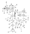
- FIG. 1 is a schematic view of an optical system of the fundus camera of the non-mydriasis type consistent with a preferred embodiment of the present invention.
- an illumination optical system 1 a photographing optical system 2
- an observation optical system 3 a fixation target projection optical system 35
- a focus index projection optical system 45 a focus index projection optical system 45.
- Illumination light emitted from a halogen lamp 10, which is a light source for observation, is changed into infrared illumination light by using an infrared filter 11 having a wavelength-selecting property which transmits infrared light with wavelengths of 750 nm or longer.
- the infrared illumination light After passing through a condenser lens 12, the infrared illumination light is reflected by a dichroic mirror 15 having a wavelength-selecting property which reflects infrared light and transmits visible light, and it illuminates a ring slit 16 having a ring-shaped aperture.
- the filter 11 is not required.
- a flash lamp 13 which is a light source for photographing
- a condenser lens 14 After visible illumination light emitted from a flash lamp 13, which is a light source for photographing, passes through a condenser lens 14, it is transmitted through the dichroic mirror 15 and becomes coaxial with the optical axis of the infrared illumination light to illuminate the ring slit 16.
- the illumination light (ring slit light) forms an intermediate image near an aperture in a mirror 21 with an aperture via a relay lens 17a, a mirror 18, a black dot plate 19 having a small dot on its center, a beam splitter 48, and a relay lens 17b, whereby the light is reflected to be coaxial with the optical axis of the photographing optic system 2.
- the illumination light (ring slit light) reflected by the mirror 21 once converges through an objective lens 20 near a pupil of an eye E to be examined, it diffuses to evenly illuminate a fundus Ef of the eye E.
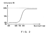
- the dichroic mirror 25 has a wavelength-selecting property of transmitting about 80% to 90% of visible light with wavelengths ranging from approximately 700 nm to 800 nm and reflecting the residual light accounting for about 20% to 10% as well as most infrared light (reflecting almost all the infrared light with wavelengths of approximately 800 nm or longer).
- Visible reflection light from the fundus Ef having passed through the dichroic mirror 25, goes into a color CCD camera 26 for photographing having a sensitivity to the visible range, and an image of the fundus Ef is formed on a photographing surface of the CCD camera 26.
- a photographed image of the fundus Ef may be used as an electrical image provided that the camera 26 is a high resolution digitized CCD camera having millions of picture elements.
- the observation optical system 3 shares the elements from the lens 20 to the dichroic mirror 25 with the photographing optical system 2, and an observation optical path P2 is divided from a photographing optical path P1 by the dichroic mirror 25.
- an observation optical path P2 is divided from a photographing optical path P1 by the dichroic mirror 25.
- a relay lens 30 After infrared reflection light from the fundus Ef reflected by the dichroic mirror 25 passes through a relay lens 30, it is further reflected by a dichroic mirror 31, which has the same wavelength-selecting property as the dichroic mirror 25, so as to enter a CCD camera 32 for observation having a sensitivity to the infrared range. Then, an image of the fundus Ef is formed on its photographing surface.
- the lens 23, which is movable along the optical axis of the optical path P0 shared by the photographing optical system 2 and the observation optical system 3, provides a way for adjustment of a refractive error to be consistent with a refractive power of the eye E.
- the lens 23 is fixedly disposed on a rack 42, and the rack 42 is engaged with a pinion 41 fixedly attached to a rotation axis of a stepping motor 40.
- the lens 23 moves on the optical axis in conjunction with the rack 42 and the pinion 41 by rotation of the motor 40, and it brings an image of the fundus Ef into focus on the photographing surfaces of the cameras 26 and 32.
- the focus index projection optical system 45 has an index plate 47, an LED 46 emitting infrared light, and a beam splitter 48, and the index plate 47 and the LED 46 move together with the lens 23.
- the infrared light for an index projection is reflected by the beam splitter 48 and the mirror 21 to form an image on a conjugate plane (not illustrated) with the fundus Ef once, and then it is projected into the fundus Ef via the lens 20.
- a conjugate plane not illustrated
- the focus index is projected on the fundus Ef by infrared light
- its infrared reflection light is reflected by the dichroic mirrors 25 and 31 and is photographed along with the image of the fundus Ef by the camera 32.
- the fixation target projection optical system 35 is disposed on the observation optical path P2 side divided from the photographing optical path P1 by the dichroic mirror 25.
- the dichroic mirror 31 further divides the observation optical path P2 into optical paths P3 and P4, and a fixation light 36 emitting visible light is provided (disposed) on the optical path P4 divided from the optical path P3 on which the camera 32 is provided (disposed).
- the fixation light 36 disposed at an end of an adjustment knob 37, is arranged to be movable within an approximately conjugate plane with the fundus Ef and the photographing surface of the camera 32.
- the fixation light 36 is moved within the plane vertical to the projection optical axis as an examiner operates the adjustment knob 37. Accordingly, the position of the fixation light presented to the eye E can be changed, and the fundus Ef can be guided to a desired position for photographing.
- the visible light emitted from the fixation light 36 is transmitted through the dichroic mirror 31 and enters the dichroic mirror 25 after passing through the lens 30. Although approximately only 20% to 10% of the visible light (the fixation target) having entered the dichroic mirror 25 is reflected, the visible light proceeds along the shared optical path P0 to be visible to the eye E and to induce eye fixation by the eye E (the visible sensitivity of a human eye is sensitive enough to catch a visible fixation target slightly reflected by the dichroic mirror 25).
- the brightness of the fixation target to be visible to the eye E may be easily increased by adjusting light quantity of the fixation light 36, and light-dividing members, such as a half mirror, may replace the dichroic mirror 31.
- the fixation light 36 when the fixation light 36 is at a conjugate position with the photographing surface of the camera 32, and when a catoptric system is provided in order that the light from the fixation light 36 forms an image on the photographing surface, an image of the fixation light along with the image of the fundus Ef can be shown on an after-mentioned liquid crystal display (LCD) 53 connected with the output of the camera 32. Accordingly, eye fixation is induced while the movement of the fixation light is observed and operated on the LCD 53.
- LCD liquid crystal display
- the dichroic mirror 25 has a wavelength-selecting property which transmits approximately 80% to 90% of visible light and reflects the residual light
- the ratio (proportion) of transmission and reflection is not limited to the specific ratio mentioned above.
- a wavelength range of reflected visible light usually remains in a part of a daichroic mirror. Accordingly, the ratio of separating visible light and infrared light may be determined in view of sensitivity of an eye E and a CCD camera and/or of light quantity of the fixation light.
- the fixation target projection optical system 35 has a fixation light embedded on the observation optical path P2 side, which is the optical path of reflected infrared light, by taking advantage of a wavelength range (properties) of reflected visible light remaining (made to remain) in a part of the dichroich mirror 25. Therefore, the embedded fixation light can be visible to the examinee, and the system may be constructed without a driving mechanism to switch optical paths, such as a pop-up mirror. In addition, when a mechanism to move the fixation light for guiding a sight line is used, its arrangement can be simplified.
- an alignment between the eye E and the optical system of the apparatus is performed.
- the optical system stored in a casing is put on a movable base, and it makes a relative movement to a fixed base by a sliding mechanism, which is not indicated in the figure.
- the eye E is illuminated by infrared illumination light by turning on the lamp 10.
- Infrared reflection light from the fundus Ef is reflected by the dichroic mirror 25, and an image of the eye E is photographed by the camera 32.
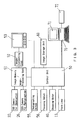
- picture signals from the camera 32 are inputted to an image memory/image-processing unit 51 and an image-converting unit 52 for converting those picture signals to picture signals for the LCD display, and then to the LCD 53, which is a liquid crystal display, whereby the image of the eye E is displayed thereon.
- the examiner While observing the image of the eye E (a monochrome image at this point) shown on the LCD 53, the examiner observes an alignment reflex formed by an alignment optical system not shown in the figure (for example, the alignment optical system may be structured by disposing the edges of a pair of right and left optical fibers emitting infrared light in front of the diaphragm 22) in order to perform an alignment for adjustment of the working distance between the eye E and the optical system and for adjustment of the optical axes.
- the alignment optical system may be structured by disposing the edges of a pair of right and left optical fibers emitting infrared light in front of the diaphragm 22
- the examiner moves the lens 23 by operating a focusing switch 56 so that the photographing surfaces of the cameras 26 and 32 are placed at conjugate positions with the fundus Ef.
- a control unit 50 rotates the motor 40 in accordance with an operational signal of the switch 56 and moves the lens 23 along the optical axis. This operation is done to correct the gap in a focus position derived from a refractive error of the eye E, to adjust the focus to the fundus Ef, and to form a clear image of the fundus Ef.
- the visible light emitted from the fixation light 36 is reflected by the dichroic mirror 25 and projected onto the fundus Ef, the visible light can be clearly recognized due to correction of a refractive error of the eye E, and then the examinee can fixate his eye to the light emitted from the fixation light 36.
- An image of a focus index (an image on an index plate 47) photographed by the camera 32 along with an image of a fundus Ef by the camera 32 is utilized for adjusting the focus by moving the lens 23.
- the examiner While observing the infrared fundus image and the image of the focus index photographed by the camera 32 and displayed on the LCD 53, the examiner operates the switch 56 to adjust the focus of the image of the focus index. By doing this operation, it is possible to correct the gap with a focus position derived from the refractive error of the eye E.
- the control unit 50 obtains a travel position (a movement amount) by recognizing the number of rotary pulses of the motor 40 and converts it into diopters indicating a refractive degree and displays on the LCD 53.
- the display of the diopter may be a guideline for the examiner to note a degree of the refractive error of the eye E.
- a degree of the refractive error is already known, a moving direction of the lens 23 is easily recognized, and the focus of the fundus image is easily adjusted by comparing the known degree and the information displayed on the LCD 53.
- the fixation light 36 can be used in a manner that the examinee can easily and clearly recognize it from the start.
- the fixation light 36 is moved in a preferred direction by operating the adjustment knob 37.
- the examiner can easily recognize where to move the fixation light 36 because the image of the fixation light 36 is shown along with the fundus image on the LCD 53.
- the examiner After completing adjustment of the focus to observe an image of the fundus Ef to be photographed, the examiner generates a trigger signal by pressing a photographing switch 55.
- a control unit 50 causes the firing (lighting) to the lamp 13 in order to illuminate the fundus Ef with visible illumination light. Visible reflection light from the fundus Ef enters the camera 26 as it proceeds along the optical path mentioned above.
- Picture signals from the camera 26 are inputted to the image memory/image-processing unit 51, and a still picture is stored in the image memory/image-processing unit 51 in synchronism with the firing (lighting) of the lamp 13.
- the photographed image is inputted into the LCD 53 via the image-converting unit 52, and the image of the fundus Ef is shown in color on the LCD 53.
- An image storage unit 60 such as an MO (a magneto-optical disk) and/or a memory card, for storing a large amount of image data is connected to the control unit 50 so that the image storage unit 60 can preserve the photographed image stored in the image memory/image-processing unit 51. It is possible that the image data stored in the image memory/image-processing unit 51 and the image storage unit 60 are output and sent to an external computer 70 connected thereto with a communication cable, so that the image of the fundus Ef is freely displayed and observed on a display 71 connected to the computer 70, and that the image is printed out by a printer 72. For example, when a memory card is used as the image storage unit 60, the computer 70 reads in the data stored in the memory card and sends them out to display the image of the fundus on the display 71, and to print it out by using the printer 72.
- a memory card is used as the image storage unit 60
- the computer 70 reads in the data stored in the memory card and sends them out to display the image of the fundus on
Landscapes
- Health & Medical Sciences (AREA)
- Life Sciences & Earth Sciences (AREA)
- Engineering & Computer Science (AREA)
- Heart & Thoracic Surgery (AREA)
- Molecular Biology (AREA)
- Biophysics (AREA)
- Ophthalmology & Optometry (AREA)
- Biomedical Technology (AREA)
- Veterinary Medicine (AREA)
- Medical Informatics (AREA)
- Physics & Mathematics (AREA)
- Surgery (AREA)
- Animal Behavior & Ethology (AREA)
- General Health & Medical Sciences (AREA)
- Public Health (AREA)
- Multimedia (AREA)
- Eye Examination Apparatus (AREA)
Abstract
Description
Claims (6)
- A fundus camera for photographing a fundus of an eye to be examined, the camera comprising:an illumination optical system for illuminating the fundus of the eye with visible illumination light for photographing and with invisible illumination light for observation;a photographing optical system having a first photographic element, for photographing an image of the fundus with visible reflection light from the fundus;an observation optical system havinga first optical path shared with the photographing optical system,a second optical path divided from an optical path of the photographing optical system by a first wavelength-selecting mirror,a third optical path further divided from the second optical path by a light-dividing member, anda second photographic element disposed on the third optical path,for photographing an image of the fundus with invisible reflection light from the fundus,wherein the first wavelength-selecting mirror has a wavelength-selecting property of transmitting either approximately all of an invisible wavelength range and a part of a visible wavelength range or almost all of the visible wavelength range and reflecting the other; anda fixation target projection optical system having the first optical path, the second optical path, a fourth optical path divided from the third optical path by the light-dividing member, and a light source for eye fixation emitting visible light disposed at a conjugate position with a photographing surface of the second photographic element on the fourth optical path.
- The fundus camera according to claim 1, further comprising a moving unit which moves the light source for eye fixation within a plane vertical to an optical axis of the fourth optical path.
- The fundus camera according to claim 1, wherein the illumination optical system includes:a visible illumination optical system, which has a first light source and illuminates the fundus with visible illumination light; andan invisible illumination optical system which has a second light source and illuminates the fundus with the invisible illumination light.
- The fundus camera according to claim 3, wherein the second light source includes a lamp emitting white illumination light, and
the invisible illumination optical system further has an infrared transmission filter and illuminates the fundus with infrared illumination light. - The fundus camera according to claim 3, further comprising a second wavelength-selecting mirror disposed on the optical paths of the visible illumination optical system and the invisible illumination optical system for making them coaxial, wherein the second wavelength-selecting mirror has a wavelength-selecting property of transmitting either the invisible wavelength range or the visible wavelength range and reflecting the other.
- The fundus camera according to claim 1, wherein the first wavelength-selecting mirror has a wavelength-selecting property of transmitting either approximately 80% to 90% or approximately 20% to 10% of a wavelength range ranging from about 700 nm to 800 nm and reflecting the other.
Applications Claiming Priority (2)
| Application Number | Priority Date | Filing Date | Title |
|---|---|---|---|
| JP2000081048 | 2000-03-22 | ||
| JP2000081048A JP3718098B2 (en) | 2000-03-22 | 2000-03-22 | Fundus camera |
Publications (3)
| Publication Number | Publication Date |
|---|---|
| EP1138256A2 true EP1138256A2 (en) | 2001-10-04 |
| EP1138256A3 EP1138256A3 (en) | 2003-07-02 |
| EP1138256B1 EP1138256B1 (en) | 2005-11-23 |
Family
ID=18598034
Family Applications (1)
| Application Number | Title | Priority Date | Filing Date |
|---|---|---|---|
| EP01107046A Expired - Lifetime EP1138256B1 (en) | 2000-03-22 | 2001-03-21 | Fundus camera with visible and infrared illumination |
Country Status (4)
| Country | Link |
|---|---|
| US (1) | US6669339B2 (en) |
| EP (1) | EP1138256B1 (en) |
| JP (1) | JP3718098B2 (en) |
| DE (1) | DE60115126T2 (en) |
Cited By (11)
| Publication number | Priority date | Publication date | Assignee | Title |
|---|---|---|---|---|
| EP1183992A3 (en) * | 2000-08-31 | 2003-01-02 | Nidek Co., Ltd. | Fundus camera |
| WO2004000109A1 (en) * | 2002-06-24 | 2003-12-31 | Medimaker Oy Ltd | Method and system for forming an image of an organ |
| EP1374757A1 (en) * | 2002-06-17 | 2004-01-02 | Canon Kabushiki Kaisha | Ophthalmologic image pickup apparatus |
| US6705726B2 (en) | 2002-02-20 | 2004-03-16 | Nidek Co., Ltd. | Instrument for eye examination and method |
| EP1340451A3 (en) * | 2002-02-20 | 2004-03-31 | Nidek Co., Ltd. | Instrument for eye examination |
| EP1452128A1 (en) * | 2003-02-28 | 2004-09-01 | Nidek Co., Ltd. | Fundus camera |
| EP1535566A1 (en) * | 2003-11-28 | 2005-06-01 | Nidek Co., Ltd. | Fundus Camera |
| DE102005003443A1 (en) * | 2005-01-21 | 2006-07-27 | Carl Zeiss Meditec Ag | Unit and method for internal vision in fundus cameras |
| EP1933276A1 (en) * | 2006-12-11 | 2008-06-18 | BrainLAB AG | Multiband tracking and calibration system |
| CN104274151A (en) * | 2013-07-05 | 2015-01-14 | 索尼公司 | Visual line detection device and visual line detection method |
| US9987093B2 (en) | 2013-07-08 | 2018-06-05 | Brainlab Ag | Single-marker navigation |
Families Citing this family (14)
| Publication number | Priority date | Publication date | Assignee | Title |
|---|---|---|---|---|
| US6637882B1 (en) | 1998-11-24 | 2003-10-28 | Welch Allyn, Inc. | Eye viewing device for retinal viewing through undilated pupil |
| CN1157153C (en) | 1998-11-24 | 2004-07-14 | 威尔驰阿林公司 | Eye viewing device for retinal viewing through undilated pupil |
| JP4172930B2 (en) * | 2001-10-31 | 2008-10-29 | 松下電器産業株式会社 | Eye imaging device and entrance / exit management system |
| AUPS158302A0 (en) * | 2002-04-09 | 2002-05-16 | Scan Optics Pty Ltd | Improved fundus camera |
| US8750702B1 (en) * | 2002-06-21 | 2014-06-10 | Rockstar Consortium Us Lp | Passive optical loopback |
| US6926407B2 (en) | 2002-06-28 | 2005-08-09 | Trefford Simpson | Apparatus and method for measuring a hue of a predetermined primary color in reflected light |
| JP2004254945A (en) * | 2003-02-26 | 2004-09-16 | Nidek Co Ltd | Fundus camera |
| JP4138571B2 (en) | 2003-05-02 | 2008-08-27 | 株式会社ニデック | Optometry equipment |
| US7052134B2 (en) | 2003-05-29 | 2006-05-30 | Nidek Co., Ltd. | Fundus camera |
| JP4047255B2 (en) * | 2003-09-25 | 2008-02-13 | 株式会社ニデック | Fundus camera |
| CA2544183A1 (en) | 2003-10-28 | 2005-05-19 | Welch Allyn, Inc. | Digital documenting ophthalmoscope |
| JP4628763B2 (en) * | 2004-12-01 | 2011-02-09 | 株式会社ニデック | Fundus camera |
| DE102005003440B4 (en) * | 2005-01-21 | 2020-01-02 | Carl Zeiss Meditec Ag | Focusing device for ophthalmic devices, in particular fundus cameras and method for the use thereof |
| EP1883354A2 (en) * | 2005-04-29 | 2008-02-06 | Novadaq Technologies Inc. | Choroid and retinal imaging and treatment system |
Family Cites Families (21)
| Publication number | Priority date | Publication date | Assignee | Title |
|---|---|---|---|---|
| DE2843287A1 (en) * | 1977-10-05 | 1979-04-19 | Canon Kk | EYE EXAMINATION INSTRUMENT |
| JPS56151929A (en) * | 1980-04-25 | 1981-11-25 | Canon Inc | Fundus camera |
| US4572627A (en) * | 1981-11-21 | 1986-02-25 | Canon Kabushiki Kaisha | Eye fundus camera |
| JPS5889238A (en) | 1981-11-21 | 1983-05-27 | キヤノン株式会社 | Eye bottom camera |
| JPS5889237A (en) | 1981-11-21 | 1983-05-27 | キヤノン株式会社 | Eye bottom camera system |
| JPS598933A (en) | 1982-07-07 | 1984-01-18 | キヤノン株式会社 | Ophthalmic machine equipped with sight mark |
| EP0234869B1 (en) * | 1986-02-25 | 1990-12-27 | Kowa Company, Ltd. | Ophthalmological diagnosis method and apparatus |
| IT1207998B (en) | 1986-05-14 | 1989-06-01 | Ausimont Spa | CROSS-LINKING OF EPOXY RESINS BY MULTIPURPOSE PERFLUOROPOLYETERS. |
| US5177511A (en) * | 1986-11-08 | 1993-01-05 | G. Rodenstock Instruments Gmbh | Apparatus for producing images of an object and in particular for observing the rear portions of the eye |
| JPS63238843A (en) * | 1987-03-27 | 1988-10-04 | 興和株式会社 | Ophthalmic diagnostic method and apparatus |
| JP2942321B2 (en) * | 1990-08-10 | 1999-08-30 | 株式会社ニデック | Transillumination imaging equipment |
| JPH0515495A (en) | 1991-07-08 | 1993-01-26 | Topcon Corp | Fundus camera |
| US5302988A (en) | 1992-03-31 | 1994-04-12 | Nidek Co., Ltd. | Stereoscopic retinal camera including vertically symmetrical apertures |
| JP3379594B2 (en) * | 1993-11-15 | 2003-02-24 | 株式会社トプコン | Ophthalmic equipment |
| JP3408308B2 (en) * | 1994-02-02 | 2003-05-19 | 株式会社ニデック | Fundus camera |
| JPH0866371A (en) | 1994-08-30 | 1996-03-12 | Canon Inc | Ophthalmic instrument |
| JP3539816B2 (en) * | 1996-01-31 | 2004-07-07 | 株式会社ニデック | Fundus camera |
| JPH10118030A (en) | 1996-10-16 | 1998-05-12 | Canon Inc | Fundus imaging device |
| JP3592050B2 (en) | 1997-10-03 | 2004-11-24 | キヤノン株式会社 | Ophthalmic equipment |
| JP2000098290A (en) * | 1998-09-28 | 2000-04-07 | Nidek Co Ltd | Optical device |
| JP4231146B2 (en) * | 1999-04-05 | 2009-02-25 | 株式会社トプコン | Fundus camera |
-
2000
- 2000-03-22 JP JP2000081048A patent/JP3718098B2/en not_active Expired - Fee Related
-
2001
- 2001-03-21 EP EP01107046A patent/EP1138256B1/en not_active Expired - Lifetime
- 2001-03-21 DE DE60115126T patent/DE60115126T2/en not_active Expired - Lifetime
- 2001-03-21 US US09/813,019 patent/US6669339B2/en not_active Expired - Fee Related
Cited By (18)
| Publication number | Priority date | Publication date | Assignee | Title |
|---|---|---|---|---|
| EP1183992A3 (en) * | 2000-08-31 | 2003-01-02 | Nidek Co., Ltd. | Fundus camera |
| US6968127B2 (en) | 2000-08-31 | 2005-11-22 | Nidek Co., Ltd. | Fundus camera |
| US6705726B2 (en) | 2002-02-20 | 2004-03-16 | Nidek Co., Ltd. | Instrument for eye examination and method |
| EP1340451A3 (en) * | 2002-02-20 | 2004-03-31 | Nidek Co., Ltd. | Instrument for eye examination |
| US7216979B2 (en) | 2002-06-17 | 2007-05-15 | Canon Kabushiki Kaisha | Ophthalmologic image pickup apparatus |
| EP1374757A1 (en) * | 2002-06-17 | 2004-01-02 | Canon Kabushiki Kaisha | Ophthalmologic image pickup apparatus |
| CN1301680C (en) * | 2002-06-17 | 2007-02-28 | 佳能株式会社 | Ophthalmic camera device |
| WO2004000109A1 (en) * | 2002-06-24 | 2003-12-31 | Medimaker Oy Ltd | Method and system for forming an image of an organ |
| EP1452128A1 (en) * | 2003-02-28 | 2004-09-01 | Nidek Co., Ltd. | Fundus camera |
| US7275824B2 (en) | 2003-02-28 | 2007-10-02 | Nidek Co. Ltd. | Fundus camera |
| US7331670B2 (en) | 2003-11-28 | 2008-02-19 | Nidek Co., Ltd | Fundus camera |
| EP1535566A1 (en) * | 2003-11-28 | 2005-06-01 | Nidek Co., Ltd. | Fundus Camera |
| DE102005003443A1 (en) * | 2005-01-21 | 2006-07-27 | Carl Zeiss Meditec Ag | Unit and method for internal vision in fundus cameras |
| EP1933276A1 (en) * | 2006-12-11 | 2008-06-18 | BrainLAB AG | Multiband tracking and calibration system |
| US7728280B2 (en) | 2006-12-11 | 2010-06-01 | Brainlab Ag | Multi-band tracking and calibration system |
| CN104274151A (en) * | 2013-07-05 | 2015-01-14 | 索尼公司 | Visual line detection device and visual line detection method |
| CN104274151B (en) * | 2013-07-05 | 2017-09-12 | 索尼公司 | Sight line detector and method for detecting sight line |
| US9987093B2 (en) | 2013-07-08 | 2018-06-05 | Brainlab Ag | Single-marker navigation |
Also Published As
| Publication number | Publication date |
|---|---|
| DE60115126T2 (en) | 2006-08-03 |
| US20010024263A1 (en) | 2001-09-27 |
| DE60115126D1 (en) | 2005-12-29 |
| US6669339B2 (en) | 2003-12-30 |
| JP3718098B2 (en) | 2005-11-16 |
| JP2001258847A (en) | 2001-09-25 |
| EP1138256B1 (en) | 2005-11-23 |
| EP1138256A3 (en) | 2003-07-02 |
Similar Documents
| Publication | Publication Date | Title |
|---|---|---|
| US6669339B2 (en) | Fundus camera | |
| US5742374A (en) | Fundus camera | |
| US5757462A (en) | Ophthalmic apparatus for photographing a section of an anterior part of an eye | |
| JP3465997B2 (en) | Fundus camera | |
| US7052134B2 (en) | Fundus camera | |
| US5543865A (en) | Fundus camera with partially common coaxial observation and photographing optical systems | |
| CN211270678U (en) | Optical system of fundus camera and fundus camera | |
| US6755526B2 (en) | Fundus camera | |
| US20040169818A1 (en) | Fundus camera | |
| US5371557A (en) | Stereoscopic retinal camera | |
| US4572627A (en) | Eye fundus camera | |
| US5420650A (en) | Eye examining apparatus including an eye refraction measuring system and eye fundus examining system | |
| US7431456B2 (en) | Fundus camera | |
| CN115956876B (en) | Fundus camera optical system with aperture and fundus camera | |
| JP3839216B2 (en) | Fundus camera | |
| US20040165872A1 (en) | Fundus camera | |
| JP3630908B2 (en) | Handheld fundus camera | |
| JPH11313800A (en) | Ophthalmic equipment | |
| JP2000107134A (en) | Ophthalmic imaging equipment | |
| JPH0638929A (en) | Ophthalmic equipment | |
| JP3630887B2 (en) | Handheld fundus camera | |
| JP2003225208A (en) | Fundus camera | |
| JPH06237901A (en) | Fundus camera | |
| JPH0595903A (en) | Ophthalmic device | |
| CN212346501U (en) | Stray light eliminating system of fundus camera |
Legal Events
| Date | Code | Title | Description |
|---|---|---|---|
| PUAI | Public reference made under article 153(3) epc to a published international application that has entered the european phase |
Free format text: ORIGINAL CODE: 0009012 |
|
| AK | Designated contracting states |
Kind code of ref document: A2 Designated state(s): AT BE CH CY DE DK ES FI FR GB GR IE IT LI LU MC NL PT SE TR |
|
| AX | Request for extension of the european patent |
Free format text: AL;LT;LV;MK;RO;SI |
|
| PUAL | Search report despatched |
Free format text: ORIGINAL CODE: 0009013 |
|
| AK | Designated contracting states |
Designated state(s): AT BE CH CY DE DK ES FI FR GB GR IE IT LI LU MC NL PT SE TR |
|
| AX | Request for extension of the european patent |
Extension state: AL LT LV MK RO SI |
|
| RIC1 | Information provided on ipc code assigned before grant |
Ipc: 7A 61B 3/12 A Ipc: 7A 61B 3/15 B Ipc: 7A 61B 3/14 B Ipc: 7G 02B 27/14 B |
|
| 17P | Request for examination filed |
Effective date: 20031113 |
|
| 17Q | First examination report despatched |
Effective date: 20031208 |
|
| AKX | Designation fees paid |
Designated state(s): DE FR GB |
|
| GRAP | Despatch of communication of intention to grant a patent |
Free format text: ORIGINAL CODE: EPIDOSNIGR1 |
|
| GRAS | Grant fee paid |
Free format text: ORIGINAL CODE: EPIDOSNIGR3 |
|
| GRAA | (expected) grant |
Free format text: ORIGINAL CODE: 0009210 |
|
| RTI1 | Title (correction) |
Free format text: FUNDUS CAMERA WITH VISIBLE AND INFRARED ILLUMINATION |
|
| AK | Designated contracting states |
Kind code of ref document: B1 Designated state(s): DE FR GB |
|
| REG | Reference to a national code |
Ref country code: GB Ref legal event code: FG4D |
|
| REF | Corresponds to: |
Ref document number: 60115126 Country of ref document: DE Date of ref document: 20051229 Kind code of ref document: P |
|
| ET | Fr: translation filed | ||
| PLBE | No opposition filed within time limit |
Free format text: ORIGINAL CODE: 0009261 |
|
| STAA | Information on the status of an ep patent application or granted ep patent |
Free format text: STATUS: NO OPPOSITION FILED WITHIN TIME LIMIT |
|
| 26N | No opposition filed |
Effective date: 20060824 |
|
| PGFP | Annual fee paid to national office [announced via postgrant information from national office to epo] |
Ref country code: FR Payment date: 20130325 Year of fee payment: 13 |
|
| PGFP | Annual fee paid to national office [announced via postgrant information from national office to epo] |
Ref country code: GB Payment date: 20140319 Year of fee payment: 14 |
|
| PGFP | Annual fee paid to national office [announced via postgrant information from national office to epo] |
Ref country code: DE Payment date: 20140417 Year of fee payment: 14 |
|
| REG | Reference to a national code |
Ref country code: FR Ref legal event code: ST Effective date: 20141128 |
|
| PG25 | Lapsed in a contracting state [announced via postgrant information from national office to epo] |
Ref country code: FR Free format text: LAPSE BECAUSE OF NON-PAYMENT OF DUE FEES Effective date: 20140331 |
|
| REG | Reference to a national code |
Ref country code: DE Ref legal event code: R119 Ref document number: 60115126 Country of ref document: DE |
|
| GBPC | Gb: european patent ceased through non-payment of renewal fee |
Effective date: 20150321 |
|
| PG25 | Lapsed in a contracting state [announced via postgrant information from national office to epo] |
Ref country code: DE Free format text: LAPSE BECAUSE OF NON-PAYMENT OF DUE FEES Effective date: 20151001 Ref country code: GB Free format text: LAPSE BECAUSE OF NON-PAYMENT OF DUE FEES Effective date: 20150321 |