EP1137276A2 - Projection TV cabinet concept with all critical alignment parts mounted to one reference part - Google Patents
Projection TV cabinet concept with all critical alignment parts mounted to one reference part Download PDFInfo
- Publication number
- EP1137276A2 EP1137276A2 EP01101701A EP01101701A EP1137276A2 EP 1137276 A2 EP1137276 A2 EP 1137276A2 EP 01101701 A EP01101701 A EP 01101701A EP 01101701 A EP01101701 A EP 01101701A EP 1137276 A2 EP1137276 A2 EP 1137276A2
- Authority
- EP
- European Patent Office
- Prior art keywords
- components
- cabinet
- cabinet according
- screen
- mirror
- Prior art date
- Legal status (The legal status is an assumption and is not a legal conclusion. Google has not performed a legal analysis and makes no representation as to the accuracy of the status listed.)
- Withdrawn
Links
Images



Classifications
-
- H—ELECTRICITY
- H04—ELECTRIC COMMUNICATION TECHNIQUE
- H04N—PICTORIAL COMMUNICATION, e.g. TELEVISION
- H04N5/00—Details of television systems
- H04N5/74—Projection arrangements for image reproduction, e.g. using eidophor
-
- H—ELECTRICITY
- H04—ELECTRIC COMMUNICATION TECHNIQUE
- H04N—PICTORIAL COMMUNICATION, e.g. TELEVISION
- H04N9/00—Details of colour television systems
- H04N9/12—Picture reproducers
- H04N9/31—Projection devices for colour picture display, e.g. using electronic spatial light modulators [ESLM]
- H04N9/3141—Constructional details thereof
Definitions
- the present invention relates to projection television systems, and more particularly, to a molded plastic television cabinet having reference features molded into one part for aligning the critical optical components of the projection television system.
- a conventional projection television (TV) system typically consists of a plurality of critical optical components mounted in a multi-part cabinet structure.
- the optical components commonly include a light projector assembly for generating television images, a screen for viewing the images, and a large mirror (often combined with a smaller mirror) for directing the images generated by the light projector assembly to the screen.
- the multi-part cabinet structure usually includes a front section having a screen frame that mounts the screen, a rear section or back cover which mounts the large mirror, a first bracket for mounting the small mirror, and a second bracket for mounting the light projector assembly to the cabinet front section.
- Each optical component/cabinet part interface adds tolerance stack to the TV system.
- the large mirror is mounted to a multi-piece sheet metal structure that is mounted to the cabinet front section along with the light projector assembly and the screen. The use of such a multi-piece sheet metal structure to hold the large mirror adds additional tolerance stack into the TV system.
- the invention is directed to a cabinet for a projection television system having a plurality of optical components.
- the cabinet includes a one-piece molded structure for mounting the components; and locating features unitary with the structure and for optically aligning the components with one another.
- the locating features advantageously minimize tolerance stacks for mounting the components.
- the optical components can include a light projector assembly for generating images, a screen for viewing the images, and at least one mirror for directing the images generated by the light projector assembly to the screen.
- the locating features can include a pocket and at least one slot that define a reference plane for the mirror; a pocket that defines a reference plane for the screen or a plurality of fastener bosses that define a reference plane for the screen; or a vertical wall that defines a reference plane for the light projector assembly.
- a cabinet for a projection television system the projection television system has a plurality of optical components and the cabinet includes a one-piece enclosure for mounting the components; and reference surfaces unitary with the enclosure, for optically aligning the components with one another.
- a cabinet for a projection television system having a plurality of optical components
- the cabinet includes a one-piece molded structure for mounting the components, and locating means unitary with the structure, for mechanically aligning the components with one another.
- a cabinet for a projection television system having a plurality of optical components and the cabinet including a one-piece enclosure for mounting the components; and reference surfaces unitary with the enclosure, for mechanically aligning the components with one another.
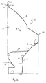
- FIGS. 1 and 2 collectively illustrate a projection TV system cabinet 10 made according to a preferred embodiment of the invention.
- the cabinet 10 generally comprises a self-supporting, one-piece, open-front enclosure 12 molded from a plastic material.
- the enclosure 12 is made using a conventional gas injection molding process which minimizes internal stresses in the enclosure 12 and thus, dimensionally stabilizes the enclosure 12.
- the lower portion 14 of the enclosure 12 defines a frame section 16 that provides the enclosure 12 with rigidity.
- the frame section 16 is covered by an inclined top wall 18 and surrounded by a pair of side walls 20 with bottom edges 22 that turn inwardly toward the lower frame section 16.
- a flange 24 is molded with front edges of the top and side walls 18, 20.
- the cabinet 10 of the invention houses all critical optical components commonly used in a projection TV system including a light projector assembly 26 for generating television images, a screen 28 for viewing the images, and a large upper mirror 30 and a smaller lower mirror 32 for directing the images generated by the light projector assembly 26 to the screen 28.
- the enclosure 12 includes locating features, which will be described further on, for referencing each of these optical components 26, 28, 30, 32 therein. These locating features are precisely molded into the enclosure 12 so that when the optical components 26, 28, 30, 32 are mounted therein, the components are properly referenced and therefore, in optical alignment with one another.
- the flange 24 includes locating features for referencing the screen 28 and the top 56 of the large upper mirror 30. More specifically, as best shown in FIGS. 1, 2, and 5, the flange 24 has molded therein a honeycomb arrangement of ribs 36.
- the rib arrangement 36 is molded to define a recessed pocket 38 having a plurality of cylindrical fastener bosses 42 which project forwardly from the bottom 40 of the pocket 38 (FIG. 2).
- the end surfaces 44 (FIG. 2) of the bosses 42 cooperate to define a reference plane for precisely locating the screen 28.
- the screen 28 includes a peripherally disposed screen bracket 46 that mounts the screen 28 to the bosses 42.
- the screen bracket 46 has an outer arm 48 and a forward arm 50.
- the outer arm 48 of the bracket 46 is secured against the end surfaces 44 of the bosses 42 via conventional screw-fasteners 52 which extend through apertures (not shown) in the outer arm 48 and thread into the bosses 42.
- the forward arm 50 of the bracket 46 defines a groove 54 that receives and grips the peripheral edges of the screen 28.
- the screen bracket 46 adds stiffness and sag resistance to the open front 13 of the enclosure 12.
- the bottom 40 of the flange pocket 38 defines a reference plane that precisely locates or references the top 56 of the upper mirror 30.
- the upper mirror 30 includes a mirror bracket 58 that mounts the top 56 of the upper mirror 30 to the bottom 40 of the flange pocket 38.
- the mirror bracket 58 is a generally planar member 60 having a plurality of apertures (not shown) that permit the bosses 42 and conventional screw fasteners (not shown) to extend therethrough, the fasteners threading into the bottom 40 of the flange pocket 38 and operating to securely retain the mirror bracket 58 against the bottom 40 of the pocket flange 38.
- the bracket 58 includes a rearwardly angled lower extension 62 that defines a shrouded support surface 64 for supporting the top 56 of the upper mirror 30.
- the frame section 16 defines a molded in angled slot 66 that precisely locates and secures the bottom 68 of the upper mirror 30 (the bottom 68 of the mirror 30 slides into the slot 66 during assembly).
- the forward side of the slot is discontinuous to facilitate a simple mold design.
- the forward side of the slot can also be made continuous if a more complicated mold is used.
- elongated H-shape clamping brackets 70 removably coupled-to the side walls 20 with screw-fasteners 72, are-provided for supporting the sides 74 of the upper mirror 30.
- slots can be molded in the side walls 20 in place of the H-shape clamping brackets 70, for supporting the sides 74 of the upper mirror 30 (the sides 74 and bottom 68 of the upper mirror 30 slide into all three slots during assembly).
- FIG. 6 depicts a cross-sectional view through the flange 24 of a cabinet according to a second embodiment of the invention where like elements are identified with like numerals.
- the honeycomb rib arrangement 38 of the flange 24 is molded with an outer pocket 80 and an inner pocket 82 which respectively locate the screen 28 and the top 56 of the upper mirror 30.
- a major portion of the periphery of the screen 28 (the top portion, side portions, and partial sections of the bottom portion) is biased against the bottom 84 of the outer pocket 80 with a conventional screen clamping bracket (not shown).
- the top of the upper mirror 30 is located and biased against the bottom 86 of the inner pocket 82 with a conventional bent-shape clamping bracket 88 and screw-fastener arrangement 90.
- the bottom 68 and sides 74 of the upper mirror 30 are located as described earlier.
- the frame section 16 forming the lower portion 14 of the cabinet enclosure 12 is molded to include a supportive bottom wall 100, and a pair of spaced-apart, boxed frame members 102 and an angled upper wall 104 disposed between the frame members 102.
- a generally vertical wall 106 for mounting the light projector assembly 26 is located between the frame members 102, and extends from the bottom edge 108 of the angled upper wall 104 to the bottom wall 100.
- the frame sections 102 are formed by stepped outer side walls 110 and opposing inner side walls 112 having molded in pockets 114 that define forwardly facing angled-down surfaces 116 for locating the lower mirror 32 of the projection TV system.
- the side edges 118 of the lower mirror 32 reference against the angled-surfaces 116 of the pockets 114 while molded in spring fingers or conventional clamping brackets (not shown) bias the lower mirror 32 against these surfaces 116 and prevent dislocation of the lower mirror 32 from the pockets 114 during impact testing.
- the light projector assembly 26 is mounted to the rear surface 120 of the vertical wall 106 using a bracket 122.
- An aperture 124 in the vertical wall 106 permits the optics 126 of the light projector assembly 26 to extend therethrough and face the angled face surface 128 of the lower mirror 32 so that images generated by the projector assembly 26 can be directed to the screen 28 by the lower and upper mirrors 32, 30. Since the vertical wall 106 is a precision molded part of the enclosure 12, the optics 126 of the projector assembly 26 can be pre-aligned with no adjustment provisions. If desired, the vertical wall 106 and the projector assembly mounting bracket 122 can be cooperatively adapted to provide the adjustability needed to achieve acceptable geometry of the light projector assembly 26.
- the enclosure 12 of the cabinet 10 can be provided with one or more decorative masks 130 that cover the flange 24 and lower cabinet details.
- a removable cover 132 is typically attached to the rear of the enclosure 12 for accessing the light projector assembly 26.
Landscapes
- Engineering & Computer Science (AREA)
- Multimedia (AREA)
- Signal Processing (AREA)
- Projection Apparatus (AREA)
- Transforming Electric Information Into Light Information (AREA)
Abstract
Description
Claims (22)
- A cabinet for a projection television system, the projection television system having a plurality of optical components, the cabinet comprising:a one-piece molded structure for mounting the components; andlocating features unitary with the structure and for optically aligning the components with one another.
- The cabinet according to claim 1, wherein the optical components include a light projector assembly for generating images, a screen for viewing the images, and at least one mirror for directing the images generated by the projector assembly to the screen.
- The cabinet according to -claim 2, wherein the locating features comprise a plurality of reference surfaces.
- The cabinet according to claim 1, wherein the optical components include a mirror and the locating features include a pocket and at least one slot that define a reference plane for the mirror.
- The cabinet according to claim 1, wherein the optical components include a screen and the locating features include a pocket that defines a reference plane for the screen.
- The cabinet according to claim 1, wherein the optical components include a screen and the locating features include a plurality of fastener bosses and/or ribs that define a reference plane for the screen.
- The cabinet according to claim 1, wherein the optical components include a light projector assembly and the locating features include a vertical wall that defines a reference surface for the light projector assembly.
- The cabinet according to claim 1, wherein the optical components include a mirror and the locating features include two pockets that define a reference plane for the mirror.
- The cabinet according to claim 1, wherein the locating features include at least one pocket that defines a reference plane for at least one of the components.
- The cabinet according to claim 1, wherein the locating features include a vertical wall that defines a reference surface for at least one of the components.
- The cabinet according to claim 1, wherein the locating features include at least one slot that defines a reference plane for at least one of the components.
- The cabinet according to claim 1, wherein the enclosure is molded from plastic.
- Tbe cabinet according to claim 1, wherein the locating features minimize tolerance stacks for mounting the components.
- A cabinet for a projection television system, the projection television system having a plurality of optical components, the cabinet comprising:a one-piece enclosure for mounting the components; andreference surfaces unitary with the enclosure, for optically aligning the components with one another.
- The cabinet according to claim 14, wherein the components include a mirror and the reference surfaces include a pocket and at least one slot that define a reference plane for the mirror.
- The cabinet according to claim 15, wherein the components include a second mirror and the reference surfaces include two pockets that define a reference plane for the second mirror.
- The cabinet according to claim 14, wherein the components include a screen and the reference surfaces include a pocket that defines a reference plane for the screen.
- The cabinet according to claim 14, wherein the components include a screen and the reference surfaces include a plurality of fastener bosses and/or ribs that define a reference plane for the screen.
- The cabinet according to claim 14, wherein the components include a light projector assembly and the reference surfaces include a vertical wall that defines a reference surface for the light projector assembly.
- The cabinet according to claim 14, wherein the enclosure is molded from plastic and the locating surfaces minimize tolerance stacks for mounting the components.
- A cabinet for a projection television system, the projection television system having a plurality of optical components, the cabinet comprising:a one-piece molded structure for mounting the components; andlocating means unitary with the structure, for mechanically aligning the components with one another.
- A cabinet for a projection television system, the projection television system having a plurality of optical components, the cabinet comprising:a one-piece enclosure for mounting the components; andreference surfaces unitary with the enclosure, for mechanically aligning the components with one another.
Applications Claiming Priority (4)
| Application Number | Priority Date | Filing Date | Title |
|---|---|---|---|
| US17833000P | 2000-01-27 | 2000-01-27 | |
| US09/597,802 US6921174B1 (en) | 2000-01-27 | 2000-06-20 | Projection television cabinet having a one-piece reference structure |
| US597802 | 2000-06-20 | ||
| US178330 | 2000-06-20 |
Publications (2)
| Publication Number | Publication Date |
|---|---|
| EP1137276A2 true EP1137276A2 (en) | 2001-09-26 |
| EP1137276A3 EP1137276A3 (en) | 2002-02-20 |
Family
ID=26874207
Family Applications (1)
| Application Number | Title | Priority Date | Filing Date |
|---|---|---|---|
| EP01101701A Withdrawn EP1137276A3 (en) | 2000-01-27 | 2001-01-25 | Projection TV cabinet concept with all critical alignment parts mounted to one reference part |
Country Status (6)
| Country | Link |
|---|---|
| US (1) | US6921174B1 (en) |
| EP (1) | EP1137276A3 (en) |
| JP (1) | JP2001251570A (en) |
| KR (1) | KR100806150B1 (en) |
| CN (1) | CN1310548A (en) |
| MX (1) | MXPA01000955A (en) |
Cited By (2)
| Publication number | Priority date | Publication date | Assignee | Title |
|---|---|---|---|---|
| WO2006074102A1 (en) * | 2005-01-05 | 2006-07-13 | Tte Technology, Inc. | Method and system for mounting a light engine assembly |
| US7176986B2 (en) | 2002-08-31 | 2007-02-13 | Samsung Electronics Co., Ltd. | Projection television |
Families Citing this family (21)
| Publication number | Priority date | Publication date | Assignee | Title |
|---|---|---|---|---|
| US6545729B1 (en) * | 2000-08-18 | 2003-04-08 | Mitsubishi Digital Electronics America, Inc. | Foam cabinetry for electronic devices |
| KR100465306B1 (en) * | 2001-12-29 | 2005-01-13 | 엘지전자 주식회사 | Structure for projection television and method thereon |
| JP4515076B2 (en) * | 2003-11-12 | 2010-07-28 | 株式会社平和 | Game machine projection equipment |
| US20070229959A1 (en) * | 2004-04-29 | 2007-10-04 | Duggan Scott J | Light Box Barrier System for a Projection Display |
| JP2007536571A (en) * | 2004-05-04 | 2007-12-13 | トムソン ライセンシング | Light engine mount structure for projection display |
| TWI246327B (en) * | 2004-09-10 | 2005-12-21 | Coretronic Corp | A modular rear projector and a combination structure used in a rear projector |
| US20060152685A1 (en) * | 2005-01-11 | 2006-07-13 | Tsen-Hwang Lin | Optic projecting method and structure of rear projection TV for dual projecting system |
| US7413315B2 (en) * | 2005-09-21 | 2008-08-19 | N-Lighten Technologies | Integrated optical assembly and method for projection displays |
| US7805260B2 (en) * | 2005-11-23 | 2010-09-28 | Electric Mirror, Llc | Mirror assembly |
| US7853414B2 (en) * | 2005-11-23 | 2010-12-14 | Electric Mirror, Llc | Mounting structure for a mirror assembly |
| WO2007062409A2 (en) * | 2005-11-23 | 2007-05-31 | Electric Mirror, L.L.C. | Back lit mirror with media display device |
| JP2007183302A (en) * | 2005-12-29 | 2007-07-19 | Sony Corp | Rear projection display device |
| JP2007183301A (en) * | 2005-12-29 | 2007-07-19 | Sony Corp | Rear projection display device |
| JP2009524079A (en) * | 2006-01-17 | 2009-06-25 | トムソン ライセンシング | Compatible projection television screen mounting clamp |
| KR20070090672A (en) * | 2006-03-03 | 2007-09-06 | 삼성전자주식회사 | Projection type display device |
| JP2007322711A (en) * | 2006-05-31 | 2007-12-13 | Sony Corp | Rear projection display device |
| JP2009192601A (en) * | 2008-02-12 | 2009-08-27 | Mitsubishi Electric Corp | Projection television |
| JP5349355B2 (en) * | 2010-02-01 | 2013-11-20 | 三菱電機株式会社 | Projection television and projection television screen unit fixing method |
| JP5499813B2 (en) * | 2010-03-23 | 2014-05-21 | 三菱電機株式会社 | Projection type image display device |
| JP5535330B2 (en) * | 2010-09-30 | 2014-07-02 | 日立コンシューマエレクトロニクス株式会社 | Projection display device |
| CN111045186A (en) * | 2019-12-30 | 2020-04-21 | 长春奥普光电技术股份有限公司 | SIC reflector with supporting reference structure |
Family Cites Families (27)
| Publication number | Priority date | Publication date | Assignee | Title |
|---|---|---|---|---|
| US3804504A (en) * | 1972-09-18 | 1974-04-16 | M Scott | Mini-theater |
| US3930701A (en) | 1973-12-10 | 1976-01-06 | Otakie Daniel A | Portable television cabinet surface extender |
| US4006300A (en) * | 1975-12-31 | 1977-02-01 | Zenith Radio Corporation | Two-piece back for a console television receiver |
| JPS593664Y2 (en) | 1978-09-20 | 1984-02-01 | ソニー株式会社 | Mirror opening/closing device in video projector |
| US4491872A (en) * | 1981-01-26 | 1985-01-01 | Zenith Electronics Corporation | Ultra-compact projection television receiver |
| US4506295A (en) * | 1982-07-30 | 1985-03-19 | Rca Corporation | Projection television receiver with unitary optics frame |
| US4512631A (en) * | 1983-04-21 | 1985-04-23 | Rca Corporation | Rear projection television screen incorporating a prism lens |
| US4482206A (en) * | 1983-04-21 | 1984-11-13 | Rca Corporation | Rear projection television screen having a multi-surface Fresnel lens |
| US4544946A (en) * | 1983-04-21 | 1985-10-01 | Rca Corporation | Vertical color shift correction in a rear projection television screen |
| US4556913A (en) * | 1984-01-13 | 1985-12-03 | Rca Corporation | Apparatus for preventing virtual images in projection television receivers |
| US4827439A (en) | 1987-12-04 | 1989-05-02 | Texas Instruments Incorporated | Factory floor operator interface console |
| JPH0787561B2 (en) | 1988-03-08 | 1995-09-20 | パイオニア株式会社 | Connecting member for projection TV unit and multi-projection TV |
| JPH04132376A (en) | 1990-09-21 | 1992-05-06 | Matsushita Electric Ind Co Ltd | Body of equipment for television receiver |
| US5363149A (en) | 1992-04-23 | 1994-11-08 | Pioneer Electronic Corporation | Projection television set |
| KR200147795Y1 (en) | 1993-01-29 | 1999-06-15 | 윤종용 | A projection type tv having a movable reflective mirror |
| ES2125740B1 (en) | 1993-02-12 | 1999-11-16 | Sony Corp | REAR PROJECTOR HAS AN ANGLE-INCLUDED ANGLE DISPLAY MOUNT FRAME |
| US5808704A (en) | 1994-01-17 | 1998-09-15 | Hitachi, Ltd. | Rear projection type image display apparatus |
| JPH0965250A (en) | 1995-08-18 | 1997-03-07 | Sony Corp | Monitor equipment cabinet |
| US5742359A (en) | 1995-08-23 | 1998-04-21 | Samsung Electronics Ltd. | Electronic appliance with construction capable of easily maintaining desired contact space between its control knob and switch |
| JP3381181B2 (en) | 1995-09-29 | 2003-02-24 | ソニー株式会社 | LCD rear projection TV |
| JP3367343B2 (en) | 1996-07-22 | 2003-01-14 | 松下電器産業株式会社 | Cabinet device of projection television receiver, molding die and resin molding method |
| JPH1051713A (en) | 1996-08-02 | 1998-02-20 | Mitsubishi Electric Corp | Projection Television Display Holder |
| US5669681A (en) | 1996-08-22 | 1997-09-23 | Sony Corporation | Mirror securing device |
| EP0830021A3 (en) | 1996-09-11 | 1999-03-31 | Projectavision, Inc. | Dual-use video display system |
| KR200197166Y1 (en) | 1996-12-21 | 2000-10-02 | 윤종용 | Display capable of mounting shield unit easily |
| US6709114B1 (en) * | 2000-01-27 | 2004-03-23 | Thomson Licensing S.A. | Spherical mounting system for three axis adjustment of light projector assembly in a projection television |
| KR100357713B1 (en) * | 2000-02-03 | 2002-10-25 | 삼성전자 주식회사 | Projection monitor having a darkroom |
-
2000
- 2000-06-20 US US09/597,802 patent/US6921174B1/en not_active Expired - Fee Related
-
2001
- 2001-01-18 KR KR1020010002851A patent/KR100806150B1/en not_active Expired - Fee Related
- 2001-01-25 EP EP01101701A patent/EP1137276A3/en not_active Withdrawn
- 2001-01-26 JP JP2001018696A patent/JP2001251570A/en not_active Withdrawn
- 2001-01-26 MX MXPA01000955A patent/MXPA01000955A/en active IP Right Grant
- 2001-01-27 CN CN01104588A patent/CN1310548A/en active Pending
Cited By (4)
| Publication number | Priority date | Publication date | Assignee | Title |
|---|---|---|---|---|
| US7176986B2 (en) | 2002-08-31 | 2007-02-13 | Samsung Electronics Co., Ltd. | Projection television |
| WO2006074102A1 (en) * | 2005-01-05 | 2006-07-13 | Tte Technology, Inc. | Method and system for mounting a light engine assembly |
| CN100538505C (en) * | 2005-01-05 | 2009-09-09 | 深圳Tcl新技术有限公司 | Method and system for mounting a light engine assembly |
| US7731369B2 (en) | 2005-01-05 | 2010-06-08 | Tte Technology Inc. | Method and system for mounting a light engine assembly |
Also Published As
| Publication number | Publication date |
|---|---|
| KR100806150B1 (en) | 2008-02-22 |
| EP1137276A3 (en) | 2002-02-20 |
| US6921174B1 (en) | 2005-07-26 |
| CN1310548A (en) | 2001-08-29 |
| KR20010078002A (en) | 2001-08-20 |
| JP2001251570A (en) | 2001-09-14 |
| MXPA01000955A (en) | 2004-07-30 |
Similar Documents
| Publication | Publication Date | Title |
|---|---|---|
| US6921174B1 (en) | Projection television cabinet having a one-piece reference structure | |
| KR100776003B1 (en) | Projection TV and its manufacturing method | |
| US7002640B2 (en) | Apparatus for mounting a screen in a projection television | |
| JP2001054039A (en) | Projection television receiver | |
| US20060146298A1 (en) | Adjustable lens module and image projector applied with the same | |
| US20070177063A1 (en) | Rear projection display apparatus | |
| US6536855B2 (en) | Front cabinet and television set | |
| US6459531B1 (en) | Screen mounting device for projection TV | |
| US6933987B2 (en) | Multi channel imaging engine apparatus | |
| CN1322745C (en) | Structure of projection TV. and its manufacturing method | |
| JPH05183847A (en) | Projection tv | |
| KR100556243B1 (en) | Projection television | |
| EP1743480B1 (en) | Structure for mounting a light engine in a projection display | |
| US20030124947A1 (en) | Light bulb assembly with reduced tolerance | |
| KR100424696B1 (en) | Projection lens unit for projector | |
| US20070195286A1 (en) | Rear projection display apparatus | |
| JP3483388B2 (en) | Shield plate mounting structure | |
| JP3272637B2 (en) | Focus plate adjustment mechanism | |
| JPS636940Y2 (en) | ||
| JPH10123966A (en) | Optical filter mounting structure | |
| JP2004219498A (en) | Camera viewfinder | |
| JPH08127197A (en) | Electronic blackboard | |
| JPH1164963A (en) | Camera film tunnel members | |
| JPS59165042A (en) | Projector for deskwork | |
| JP2005010568A (en) | Projection television and its mirror cover |
Legal Events
| Date | Code | Title | Description |
|---|---|---|---|
| PUAI | Public reference made under article 153(3) epc to a published international application that has entered the european phase |
Free format text: ORIGINAL CODE: 0009012 |
|
| AK | Designated contracting states |
Kind code of ref document: A2 Designated state(s): DE FR GB IT Kind code of ref document: A2 Designated state(s): AT BE CH CY DE DK ES FI FR GB GR IE IT LI LU MC NL PT SE TR |
|
| AX | Request for extension of the european patent |
Free format text: AL;LT;LV;MK;RO;SI |
|
| PUAL | Search report despatched |
Free format text: ORIGINAL CODE: 0009013 |
|
| AK | Designated contracting states |
Kind code of ref document: A3 Designated state(s): AT BE CH CY DE DK ES FI FR GB GR IE IT LI LU MC NL PT SE TR |
|
| AX | Request for extension of the european patent |
Free format text: AL;LT;LV;MK;RO;SI |
|
| 17P | Request for examination filed |
Effective date: 20020710 |
|
| AKX | Designation fees paid |
Free format text: DE FR GB IT |
|
| RAP1 | Party data changed (applicant data changed or rights of an application transferred) |
Owner name: THOMSON LICENSING |
|
| 17Q | First examination report despatched |
Effective date: 20071227 |
|
| STAA | Information on the status of an ep patent application or granted ep patent |
Free format text: STATUS: THE APPLICATION HAS BEEN WITHDRAWN |
|
| 18W | Application withdrawn |
Effective date: 20080623 |