EP1137211A1 - Radio transmitter/receiver and method of radio communication - Google Patents
Radio transmitter/receiver and method of radio communication Download PDFInfo
- Publication number
- EP1137211A1 EP1137211A1 EP20000960962 EP00960962A EP1137211A1 EP 1137211 A1 EP1137211 A1 EP 1137211A1 EP 20000960962 EP20000960962 EP 20000960962 EP 00960962 A EP00960962 A EP 00960962A EP 1137211 A1 EP1137211 A1 EP 1137211A1
- Authority
- EP
- European Patent Office
- Prior art keywords
- signal
- radio
- section
- pilot signal
- spreading
- Prior art date
- Legal status (The legal status is an assumption and is not a legal conclusion. Google has not performed a legal analysis and makes no representation as to the accuracy of the status listed.)
- Withdrawn
Links
Images




Classifications
-
- H—ELECTRICITY
- H03—ELECTRONIC CIRCUITRY
- H03D—DEMODULATION OR TRANSFERENCE OF MODULATION FROM ONE CARRIER TO ANOTHER
- H03D7/00—Transference of modulation from one carrier to another, e.g. frequency-changing
-
- H—ELECTRICITY
- H04—ELECTRIC COMMUNICATION TECHNIQUE
- H04L—TRANSMISSION OF DIGITAL INFORMATION, e.g. TELEGRAPHIC COMMUNICATION
- H04L25/00—Baseband systems
- H04L25/02—Details ; arrangements for supplying electrical power along data transmission lines
- H04L25/0202—Channel estimation
- H04L25/0224—Channel estimation using sounding signals
- H04L25/0226—Channel estimation using sounding signals sounding signals per se
-
- H—ELECTRICITY
- H04—ELECTRIC COMMUNICATION TECHNIQUE
- H04B—TRANSMISSION
- H04B2201/00—Indexing scheme relating to details of transmission systems not covered by a single group of H04B3/00 - H04B13/00
- H04B2201/69—Orthogonal indexing scheme relating to spread spectrum techniques in general
- H04B2201/707—Orthogonal indexing scheme relating to spread spectrum techniques in general relating to direct sequence modulation
- H04B2201/70701—Orthogonal indexing scheme relating to spread spectrum techniques in general relating to direct sequence modulation featuring pilot assisted reception
Definitions
- the present invention relates to a radio transmission/reception apparatus and radio communication method in a TDMA- or FDMA-based radio communication system.
- a base station installed for each cell assigns radio channels to a plurality of communication terminals that exist within the cell and performs radio communications simultaneously.
- TDMA Time Division Multiple Access
- FDMA Frequency Division Multiple Access
- CDMA Code Division Multiple Access
- a radio communication system using a TDMA system or FDMA system (hereinafter referred to as "TDMA/FDMA system") of these types sends data with a pilot signal to be used for channel estimations and coherent detection, etc. inserted into every slot.
- FIG.1 illustrates a slot configuration of a conventional TDMA/FDMA system. As shown in FIG.1, the conventional TDMA/FDMA system inserts a pilot signal 12 before data signal 11 that carries information.
- a guard signal 13 is inserted before the pilot signal 12 and a ramp signal 14 is inserted after the data signal 11.
- overhead sections of the guard signal 13, pilot signal 12 and ramp signal 14 except data signal 11 of the signal shown in the slot configuration diagram in FIG.1 are the parts that carry no information and it is desirable to have the shortest possible overhead sections to increase a data rate.
- the conventional TDMA/FDMA system above needs to send data with the pilot signal 12 inserted for each slot, which reduces the percentage of data signal 11 in one slot resulting in a problem of reducing the data rate.
- This object is attained by superimposing a spread pilot signal on transmission data and thereby increasing the percentage of the transmission data in one slot in the TDMA/FDMA system.
- FIG.2 is a block diagram showing a configuration of a radio transmission apparatus according to Embodiment 1 of the present invention.
- coding section 101 performs coding processing such as error correction coding on transmission data and inserts a guard signal and ramp signal.
- Modulation section 102 performs modulation such as QPSK on the output signal of coding section 101.
- Coding section 103 performs coding processing such as error correction coding on a pilot signal.
- Modulation section 104 performs primary modulation such as QPSK on the output signal of coding section 103.
- Spreading section 105 performs secondary modulation on the output signal of modulation section 104 by multiplying the signal by a specific spreading code.
- the pilot signal is spread over the entire system band or over a wide band resulting from dividing the entire system band into several portions.
- the spread pilot signal will be referred to as a "spread pilot signal”.
- Superimposing section 106 superimposes the spread pilot signal output from modulation section 105 on the output signal of spreading section 102.
- the signal resulting from superimposing the spread pilot signal on the transmission data will be referred to as a "superimposed signal”.
- Radio section 107 applies radio processing such as amplification and frequency conversion to the superimposed signal and then transmits the signal from transmission antenna 108 by time division or frequency division.
- the pilot signal is totally spread and superimposed, but it is also possible not to spread some part of the pilot signal and insert that part into the transmission data and spread and superimpose the rest of the pilot signal. This is effective when a pilot signal is assigned two or more functions such as channel estimation and coherent detection.
- the present invention is also applicable to a case where the radio transmission apparatus has a plurality of transmission systems and transmits signals of a plurality of channels.
- the radio transmission apparatus has a plurality of transmission systems and transmits signals of a plurality of channels.
- simply increasing the above components according to the transmission channels will require transmission antennas corresponding in number with the transmission channels though the number of the transmission antennas is preferred to be small.
- the signals are multiplexed and the multiplexed signal is sent from one transmission antenna. This makes it possible to increase a data rate and reduce the number of transmission antennas compared to the number of transmission channels.
- FIG.3 is a block diagram showing a configuration of the radio reception apparatus according to Embodiment 1 of the present invention.
- Radio section 202 applies radio processing such as amplification and frequency conversion to the signal received by reception antenna 201.
- Demodulation section 203 demodulates the output signal of radio section 202.
- Decoding section 204 performs decoding processing such as error correction on the output signal of demodulation section 203 and extracts reception data.
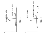
- the effect of the spread pilot signal acting as an interference component on the transmission data is small. This is because since the spread pilot signal can use a processing gain as shown in FIG.4A, it is possible to reduce the level of the spreading pilot signal to a level smaller than that of the transmission data.
- Despreading section 205 multiplies the output signal of radio section 202 by a same code as the spreading code multiplied by spreading section 105.
- Demodulation section 206 demodulates the output signal of despreading section 205.
- Decoding section 207 performs decoding processing such as error correction on the output signal of demodulation section 206. This makes it possible to extract the pilot signal spread and superimposed on a transmitting side.
- the effect of the transmission data multiplied by a spreading code by despreading section 205 acting as an interference component on the pilot signal is small. This is because the pilot signal can obtain the gain before the spreading through the despreading processing as shown in FIG.4B, while the level of the transmission data is reduced by being multiplied by the spreading code.
- the transmission data is coded by coding section 101, modulated by modulation section 102 and sent to superimposing section 106.
- the pilot signal is coded by coding section 103, modulated by modulation section 104, spread by spreading section 105 and sent to superimposing section 106.
- the spread pilot signal is superimposed on the transmission data by superimposing section 106.
- the output signal of superimposing section 106 is subjected to predetermined radio processing by radio section 107 and then sent from transmission antenna 108.
- the signal transmitted from transmission antenna 108 is received by reception antenna 201 and subjected to predetermined radio processing by radio section 202.
- the output signal of radio section 202 is demodulated by demodulation section 203, decoded by decoding section 204 and reception data is extracted.
- the output signal of radio section 202 is despread by despreading section 205, demodulated by demodulation section 206, decoded by decoding section 207 and the pilot signal is extracted.
- guard signal 302 is inserted before data signal 301
- ramp signal 303 is inserted after data signal 301
- spread pilot signal 304 is superimposed over the entire slot.
- sending transmission data with a pilot signal spread and superimposed on the transmission data eliminates the necessity of symbols, which are required for each conventional slot to transmit pilot signals and thereby makes it possible to increase the percentage of the data signal in one slot and increase the data rate.
- FIG.6 is a block diagram showing a configuration of a radio reception apparatus according to Embodiment 2 of the present invention.
- the components in FIG.6 common to those in FIG.3 are assigned the same reference numerals as those in FIG.3 and explanations thereof are omitted.
- the radio reception apparatus shown in FIG.6 adopts a configuration with channel estimation section 401 added.
- Channel estimation section 401 performs a channel estimation using a pilot signal decoded by decoding section 207 and outputs channel estimation data.
- While the conventional TDMA/FDMA system can only incorporate a pilot signal for each slot and can therefore perform channel estimations only intermittently, this embodiment can successively perform channel estimations using pilot signals transmitted at any time.
- this embodiment can increase the frequency of updating a tap coefficient of an equalizer, etc. and improve the characteristic.
- Performing channel estimations is effective especially for a long slot with a slot length of 10 ms .
- the pilot signal must be spread over a band wide enough to correctly perform a channel estimation of the data signal within a narrow band.
- FIG.7 is a block diagram showing a configuration of a radio reception apparatus according to Embodiment 3 of the present invention.
- the components in FIG.7 common to those in FIG.3 are assigned the same reference numerals as those in FIG.3 and explanations thereof are omitted.
- the radio reception apparatus shown in FIG.7 adopts a configuration with distance estimation section 501 added.
- Distance estimation section 501 performs a distance estimation using a pilot signal decoded by decoding section 207 and outputs distance estimation data.
- Embodiment 4 is intended to improve the reception quality by stripping the reception signal of the spread pilot signal.
- FIG.8 is a block diagram showing a configuration of a radio reception apparatus according to Embodiment 4 of the present invention.
- the components in FIG.8 common to those in FIG.3 are assigned the same reference numerals as those in FIG.3 and explanations thereof are omitted.
- modulation section 601 performs the same modulation processing as that in modulation section 104 on the output signal of demodulation section 206.
- Spreading section 602 performs the same spreading processing as that in spreading section 105 on the output signal of modulation section 601 and outputs a spread pilot signal.
- Elimination section 603 inputs the spread pilot signal from spreading section 602, subtracts the spread pilot signal from the output signal of radio section 202 and thereby eliminates the spread pilot signal included in the output signal of radio section 202.
- the signal output from elimination section 603 passes through a BPF (Band Pass Filter) and is demodulated in demodulation section 203, decoded by decoding section 204 and reception data is extracted.
- BPF Band Pass Filter
- the radio transmission/reception apparatus and radio communication method of the present invention can send data with a pilot signal spread and superimposed on transmission data and eliminate the necessity of a symbol which is required by a conventional TDMA/FDMA system for each slot to transmit a pilot signal, and can thereby increase the percentage of the data signal in one slot and increase the data rate.
- the present invention is ideally applicable to a radio communication base station apparatus or radio communication terminal apparatus in a TDMA-based or FDMA-based radio communication system.
Landscapes
- Engineering & Computer Science (AREA)
- Power Engineering (AREA)
- Computer Networks & Wireless Communication (AREA)
- Signal Processing (AREA)
- Mobile Radio Communication Systems (AREA)
- Transceivers (AREA)
- Time-Division Multiplex Systems (AREA)
- Transmitters (AREA)
- Circuits Of Receivers In General (AREA)
Abstract
Coding section 101 performs coding processing on
transmission data and modulation section 102 modulates
the output signal of coding section 101. Coding section
103 performs coding processing on a pilot signal,
modulation section 104 performs primary modulation on
the output signal of coding section 103 and spreading
section 105 performs secondary modulation on the output
signal of modulation section 104 by multiplying the
signal by a specific spreading code. Superimposing
section 106 superimposes the output signal of modulation
section 102 and the spread pilot signal output from
spreading section 105. Radio section 107 applies
predetermined radio processing to the superimposed
signal and then transmits the signal from transmission
antenna 108 by time division or frequency division. This
allows a radio communication system that adopts a TDMA
system or FDMA system to perform radio communications
at a high data rate.
Description
- The present invention relates to a radio transmission/reception apparatus and radio communication method in a TDMA- or FDMA-based radio communication system.
- In a radio communication system such as a cellular telephone and automobile telephone whose demand is increasing drastically in recent years, a base station installed for each cell assigns radio channels to a plurality of communication terminals that exist within the cell and performs radio communications simultaneously.
- There are three main types of system to divide a plurality of radio channels, a TDMA (Time Division Multiple Access) system, FDMA (Frequency Division Multiple Access) system and CDMA (Code Division Multiple Access) system.
- A radio communication system using a TDMA system or FDMA system (hereinafter referred to as "TDMA/FDMA system") of these types sends data with a pilot signal to be used for channel estimations and coherent detection, etc. inserted into every slot.
- FIG.1 illustrates a slot configuration of a conventional TDMA/FDMA system. As shown in FIG.1, the conventional TDMA/FDMA system inserts a
pilot signal 12 beforedata signal 11 that carries information. - Then, in order to prevent data signals of the nearest slots from overlapping with each other due to a propagation delay, etc. on a receiving side, a
guard signal 13 is inserted before thepilot signal 12 and aramp signal 14 is inserted after thedata signal 11. - Here, overhead sections of the
guard signal 13,pilot signal 12 andramp signal 14 exceptdata signal 11 of the signal shown in the slot configuration diagram in FIG.1 are the parts that carry no information and it is desirable to have the shortest possible overhead sections to increase a data rate. - However, the conventional TDMA/FDMA system above needs to send data with the
pilot signal 12 inserted for each slot, which reduces the percentage ofdata signal 11 in one slot resulting in a problem of reducing the data rate. - It is an object of the present invention to provide a radio transmission/reception apparatus and radio communication method in a TDMA/FDMA system capable of carrying out radio communications at a high data rate.
- This object is attained by superimposing a spread pilot signal on transmission data and thereby increasing the percentage of the transmission data in one slot in the TDMA/FDMA system.
-
- FIG.1 illustrates a slot configuration of a conventional TDMA/FDMA system;
- FIG.2 is a block diagram showing a configuration of a radio transmission apparatus according to Embodiment 1 of the present invention;
- FIG.3 is a block diagram showing a configuration of a radio reception apparatus according to the embodiment above;
- FIG.4A illustrates a signal level before despreading according to the embodiment above;
- FIG.4B illustrates a signal level after despreading according to the embodiment above;
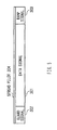
- FIG.5 illustrates a slot configuration of a superimposed signal according to the embodiment above;
- FIG.6 is a block diagram showing a configuration of a radio reception apparatus according to Embodiment 2 of the present invention;
- FIG.7 is a block diagram showing a configuration of a radio reception apparatus according to Embodiment 3 of the present invention; and
- FIG.8 is a block diagram showing a configuration of a radio reception apparatus according to Embodiment 4 of the present invention.
-
- With reference now to the attached drawings, embodiments of the present invention will be explained below.
- FIG.2 is a block diagram showing a configuration of a radio transmission apparatus according to Embodiment 1 of the present invention.
- In the radio transmission apparatus in FIG.2,
coding section 101 performs coding processing such as error correction coding on transmission data and inserts a guard signal and ramp signal.Modulation section 102 performs modulation such as QPSK on the output signal ofcoding section 101. -
Coding section 103 performs coding processing such as error correction coding on a pilot signal.Modulation section 104 performs primary modulation such as QPSK on the output signal ofcoding section 103.Spreading section 105 performs secondary modulation on the output signal ofmodulation section 104 by multiplying the signal by a specific spreading code. - The pilot signal is spread over the entire system band or over a wide band resulting from dividing the entire system band into several portions. Hereinafter, the spread pilot signal will be referred to as a "spread pilot signal".
Superimposing section 106 superimposes the spread pilot signal output frommodulation section 105 on the output signal of spreadingsection 102. Hereinafter, the signal resulting from superimposing the spread pilot signal on the transmission data will be referred to as a "superimposed signal". -
Radio section 107 applies radio processing such as amplification and frequency conversion to the superimposed signal and then transmits the signal fromtransmission antenna 108 by time division or frequency division. - By the way, in the explanation above, the pilot signal is totally spread and superimposed, but it is also possible not to spread some part of the pilot signal and insert that part into the transmission data and spread and superimpose the rest of the pilot signal. This is effective when a pilot signal is assigned two or more functions such as channel estimation and coherent detection.
- Here, the present invention is also applicable to a case where the radio transmission apparatus has a plurality of transmission systems and transmits signals of a plurality of channels. However, in this case, simply increasing the above components according to the transmission channels will require transmission antennas corresponding in number with the transmission channels though the number of the transmission antennas is preferred to be small.
- Therefore, when signals of a plurality of channels are sent, the signals are multiplexed and the multiplexed signal is sent from one transmission antenna. This makes it possible to increase a data rate and reduce the number of transmission antennas compared to the number of transmission channels.
- FIG.3 is a block diagram showing a configuration of the radio reception apparatus according to Embodiment 1 of the present invention.
-
Radio section 202 applies radio processing such as amplification and frequency conversion to the signal received byreception antenna 201. -
Demodulation section 203 demodulates the output signal ofradio section 202. Decodingsection 204 performs decoding processing such as error correction on the output signal ofdemodulation section 203 and extracts reception data. - By the way, the effect of the spread pilot signal acting as an interference component on the transmission data is small. This is because since the spread pilot signal can use a processing gain as shown in FIG.4A, it is possible to reduce the level of the spreading pilot signal to a level smaller than that of the transmission data.
- Despreading
section 205 multiplies the output signal ofradio section 202 by a same code as the spreading code multiplied by spreadingsection 105.Demodulation section 206 demodulates the output signal of despreadingsection 205. Decodingsection 207 performs decoding processing such as error correction on the output signal ofdemodulation section 206. This makes it possible to extract the pilot signal spread and superimposed on a transmitting side. - By the way, the effect of the transmission data multiplied by a spreading code by despreading
section 205 acting as an interference component on the pilot signal is small. This is because the pilot signal can obtain the gain before the spreading through the despreading processing as shown in FIG.4B, while the level of the transmission data is reduced by being multiplied by the spreading code. - Then, a signal flow between the radio transmission apparatus shown in FIG.2 and the radio reception apparatus shown in FIG.3 will be explained.
- The transmission data is coded by
coding section 101, modulated bymodulation section 102 and sent to superimposingsection 106. On the other hand, the pilot signal is coded bycoding section 103, modulated bymodulation section 104, spread by spreadingsection 105 and sent to superimposingsection 106. - The spread pilot signal is superimposed on the transmission data by superimposing
section 106. The output signal ofsuperimposing section 106 is subjected to predetermined radio processing byradio section 107 and then sent fromtransmission antenna 108. - The signal transmitted from
transmission antenna 108 is received byreception antenna 201 and subjected to predetermined radio processing byradio section 202. The output signal ofradio section 202 is demodulated bydemodulation section 203, decoded bydecoding section 204 and reception data is extracted. - On the other hand, the output signal of
radio section 202 is despread by despreadingsection 205, demodulated bydemodulation section 206, decoded bydecoding section 207 and the pilot signal is extracted. - Then, a slot configuration of the superimposed signal according to this embodiment will be explained using FIG.5.
- As shown in FIG.5, in the superimposed signal according to this embodiment,
guard signal 302 is inserted before data signal 301,ramp signal 303 is inserted after data signal 301 and spreadpilot signal 304 is superimposed over the entire slot. - In this way, sending transmission data with a pilot signal spread and superimposed on the transmission data eliminates the necessity of symbols, which are required for each conventional slot to transmit pilot signals and thereby makes it possible to increase the percentage of the data signal in one slot and increase the data rate.
- FIG.6 is a block diagram showing a configuration of a radio reception apparatus according to Embodiment 2 of the present invention. The components in FIG.6 common to those in FIG.3 are assigned the same reference numerals as those in FIG.3 and explanations thereof are omitted.
- When compared to FIG.3, the radio reception apparatus shown in FIG.6 adopts a configuration with
channel estimation section 401 added.Channel estimation section 401 performs a channel estimation using a pilot signal decoded by decodingsection 207 and outputs channel estimation data. - While the conventional TDMA/FDMA system can only incorporate a pilot signal for each slot and can therefore perform channel estimations only intermittently, this embodiment can successively perform channel estimations using pilot signals transmitted at any time.
- As a result, this embodiment can increase the frequency of updating a tap coefficient of an equalizer, etc. and improve the characteristic. Performing channel estimations is effective especially for a long slot with a slot length of 10 ms . In this case, the pilot signal must be spread over a band wide enough to correctly perform a channel estimation of the data signal within a narrow band.
- FIG.7 is a block diagram showing a configuration of a radio reception apparatus according to Embodiment 3 of the present invention. The components in FIG.7 common to those in FIG.3 are assigned the same reference numerals as those in FIG.3 and explanations thereof are omitted.
- When compared to FIG.3, the radio reception apparatus shown in FIG.7 adopts a configuration with
distance estimation section 501 added.Distance estimation section 501 performs a distance estimation using a pilot signal decoded by decodingsection 207 and outputs distance estimation data. - This makes it possible to estimate the distance from the propagation time from the transmission to reception using the received pilot signal. Since the pilot signal is spread and sent over a wide band, it is possible to calculate the propagation time from the transmission to reception with fine time resolution and thereby improve distance estimation accuracy.
- By the way, this embodiment can also be combined with Embodiment 2.
- As explained above, the reception quality in Embodiment 1 may slightly deteriorate compared to the conventional art due to influences of the spread pilot signal. To solve this problem, Embodiment 4 is intended to improve the reception quality by stripping the reception signal of the spread pilot signal.
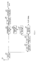
- FIG.8 is a block diagram showing a configuration of a radio reception apparatus according to Embodiment 4 of the present invention. The components in FIG.8 common to those in FIG.3 are assigned the same reference numerals as those in FIG.3 and explanations thereof are omitted.
- In the radio reception apparatus in FIG.8,
modulation section 601 performs the same modulation processing as that inmodulation section 104 on the output signal ofdemodulation section 206. Spreadingsection 602 performs the same spreading processing as that in spreadingsection 105 on the output signal ofmodulation section 601 and outputs a spread pilot signal. -
Elimination section 603 inputs the spread pilot signal from spreadingsection 602, subtracts the spread pilot signal from the output signal ofradio section 202 and thereby eliminates the spread pilot signal included in the output signal ofradio section 202. - The signal output from
elimination section 603 passes through a BPF (Band Pass Filter) and is demodulated indemodulation section 203, decoded by decodingsection 204 and reception data is extracted. - Thus, it is possible to improve the reception quality by eliminating the spread pilot signal, which becomes interference with the data signal.
- By the way, this embodiment can be combined with Embodiment 2 and Embodiment 3.
- As is clear from the above explanations, the radio transmission/reception apparatus and radio communication method of the present invention can send data with a pilot signal spread and superimposed on transmission data and eliminate the necessity of a symbol which is required by a conventional TDMA/FDMA system for each slot to transmit a pilot signal, and can thereby increase the percentage of the data signal in one slot and increase the data rate.
- Furthermore, by using a pilot signal extracted by despreading the reception signal, it is possible to successively perform channel estimations and improve distance estimation accuracy by calculating the propagation time from the transmission to reception with fine time resolution.
- This application is based on the Japanese Patent Application No.HEI 11-263600 filed on September 17, 1999, entire content of which is expressly incorporated by reference herein.
- The present invention is ideally applicable to a radio communication base station apparatus or radio communication terminal apparatus in a TDMA-based or FDMA-based radio communication system.
Claims (11)
- A radio transmission apparatus comprising:first spreading means for spreading a pilot signal;superimposing means for superimposing the spread pilot signal on transmission data; andtransmitting means for transmitting the output signal of this superimposing means by time division or frequency division.
- The radio transmission apparatus according to claim 1, wherein the transmitting means transmits a signal resulting from multiplexing signals of a plurality of channels from one transmission antenna.
- A radio reception apparatus comprising:receiving means for receiving a signal transmitted from the radio transmission apparatus according to claim 1; anddespreading means for extracting a pilot signal by despreading the output signal of this receiving means.
- The radio reception apparatus according to claim 3, further comprising channel estimating means for performing a channel estimation using the pilot signal.
- The radio reception apparatus according to claim 3, further comprising distance estimating means for performing a distance estimation using the pilot signal.
- The radio reception apparatus according to claim 3, further comprising:second spreading means for spreading the pilot signal output from the despreading means; andeliminating means for subtracting the output pilot signal of said second spreading means from the output signal of the receiving means.
- A radio communication terminal apparatus equipped with a radio transmission apparatus, said radio transmission apparatus comprising:first spreading means for spreading a pilot signal;superimposing means for superimposing the spread pilot signal on transmission data; andtransmitting means for transmitting the output signal of this superimposing means by time division or frequency division.
- A radio communication terminal apparatus equipped with a radio reception apparatus, said radio reception apparatus comprising:receiving means for receiving a signal transmitted from the radio transmission apparatus according to claim 1; anddespreading means for extracting a pilot signal by despreading the output signal of this receiving means.
- A radio communication base station apparatus equipped with a radio transmission apparatus, said radio transmission apparatus comprising:first spreading means for spreading a pilot signal;superimposing means for superimposing the spread pilot signal on transmission data; andtransmitting means for transmitting the output signal of this superimposing means by time division or frequency division.
- A radio communication base station apparatus equipped with a radio reception apparatus, said radio reception apparatus comprising:receiving means for receiving a signal transmitted from the radio transmission apparatus according to claim 1; anddespreading means for extracting a pilot signal by despreading the output signal of this receiving means.
- A radio communication method comprising steps of:spreading a pilot signal, superimposing the spread pilot signal on transmission data and transmitting the superimposed signal by time division or frequency division on a transmitting side; anddespreading the reception signal and extracting the pilot signal on a receiving side.
Applications Claiming Priority (3)
| Application Number | Priority Date | Filing Date | Title |
|---|---|---|---|
| JP26360099A JP2001086086A (en) | 1999-09-17 | 1999-09-17 | Wireless transmitting / receiving apparatus and wireless communication method |
| JP26360099 | 1999-09-17 | ||
| PCT/JP2000/006240 WO2001022634A1 (en) | 1999-09-17 | 2000-09-13 | Radio transmitter/receiver and method of radio communication |
Publications (1)
| Publication Number | Publication Date |
|---|---|
| EP1137211A1 true EP1137211A1 (en) | 2001-09-26 |
Family
ID=17391803
Family Applications (1)
| Application Number | Title | Priority Date | Filing Date |
|---|---|---|---|
| EP20000960962 Withdrawn EP1137211A1 (en) | 1999-09-17 | 2000-09-13 | Radio transmitter/receiver and method of radio communication |
Country Status (4)
| Country | Link |
|---|---|
| EP (1) | EP1137211A1 (en) |
| JP (1) | JP2001086086A (en) |
| AU (1) | AU7310700A (en) |
| WO (1) | WO2001022634A1 (en) |
Cited By (3)
| Publication number | Priority date | Publication date | Assignee | Title |
|---|---|---|---|---|
| WO2007024091A3 (en) * | 2005-08-23 | 2008-07-31 | Korea Electronics Telecomm | Transmitter in fdma communication system and method for configuring pilot channel |
| EP3113376A4 (en) * | 2014-02-28 | 2017-12-06 | Nec Corporation | Wireless transmission device, wireless reception device, wireless communication system, and wireless communication method |
| US11804870B2 (en) | 2004-01-29 | 2023-10-31 | Neo Wireless Llc | Channel probing signal for a broadband communication system |
Families Citing this family (3)
| Publication number | Priority date | Publication date | Assignee | Title |
|---|---|---|---|---|
| US7756000B2 (en) * | 2007-05-17 | 2010-07-13 | Harris Corporation | Spread baseband injected pilot carrier |
| US8213538B2 (en) * | 2007-05-29 | 2012-07-03 | Qualcomm Incorporated | Methods and apparatus for improved utilization of air link resources in a wireless communications system |
| KR101372472B1 (en) * | 2013-05-20 | 2014-03-10 | 엘아이지넥스원 주식회사 | Wireless power transfer apparatus |
Family Cites Families (6)
| Publication number | Priority date | Publication date | Assignee | Title |
|---|---|---|---|---|
| JP3312194B2 (en) * | 1996-04-18 | 2002-08-05 | シャープ株式会社 | Spread spectrum communication system |
| JPH09327073A (en) * | 1996-06-07 | 1997-12-16 | N T T Ido Tsushinmo Kk | Pilot channel allocation and transmission method in CDMA mobile communication system |
| JP3720141B2 (en) * | 1996-10-01 | 2005-11-24 | 松下電器産業株式会社 | Mobile communication method and apparatus |
| US5991334A (en) * | 1996-11-12 | 1999-11-23 | Lucent Technologies Inc. | Technique for simultaneous communications of analog frequency-modulated and digitally modulated signals using postcanceling scheme |
| JP2000069021A (en) * | 1998-08-19 | 2000-03-03 | Nippon Telegr & Teleph Corp <Ntt> | Wireless data communication transmitting / receiving method and wireless data communication transmitting / receiving device |
| JP2000307547A (en) * | 1999-04-20 | 2000-11-02 | Kokusai Electric Co Ltd | Transmission method and transmission device |
-
1999
- 1999-09-17 JP JP26360099A patent/JP2001086086A/en active Pending
-
2000
- 2000-09-13 WO PCT/JP2000/006240 patent/WO2001022634A1/en not_active Ceased
- 2000-09-13 AU AU73107/00A patent/AU7310700A/en not_active Abandoned
- 2000-09-13 EP EP20000960962 patent/EP1137211A1/en not_active Withdrawn
Non-Patent Citations (1)
| Title |
|---|
| See references of WO0122634A1 * |
Cited By (4)
| Publication number | Priority date | Publication date | Assignee | Title |
|---|---|---|---|---|
| US11804870B2 (en) | 2004-01-29 | 2023-10-31 | Neo Wireless Llc | Channel probing signal for a broadband communication system |
| WO2007024091A3 (en) * | 2005-08-23 | 2008-07-31 | Korea Electronics Telecomm | Transmitter in fdma communication system and method for configuring pilot channel |
| US7822007B2 (en) | 2005-08-23 | 2010-10-26 | Electronics And Telecommunications Research Institute | Transmitter in FDMA communication system and method for configuring pilot channel |
| EP3113376A4 (en) * | 2014-02-28 | 2017-12-06 | Nec Corporation | Wireless transmission device, wireless reception device, wireless communication system, and wireless communication method |
Also Published As
| Publication number | Publication date |
|---|---|
| WO2001022634A1 (en) | 2001-03-29 |
| AU7310700A (en) | 2001-04-24 |
| JP2001086086A (en) | 2001-03-30 |
Similar Documents
| Publication | Publication Date | Title |
|---|---|---|
| EP1028541B1 (en) | CDMA cellular radio transmission system | |
| US7733813B2 (en) | Apparatus and method for canceling interference in relay station in a communication system | |
| EP1261141B1 (en) | Interference elimination system and interference eliminating method | |
| KR100280342B1 (en) | Method for Determining Location of Mobile Station | |
| EP1094644B1 (en) | Method and apparatus for controlling transmission power in a CDMA cellular mobile telephone system | |
| US6363261B1 (en) | Extended range concentric cell base station | |
| EP1569360A1 (en) | Spread-spectrum system and method | |
| US8457102B2 (en) | Mobile wireless communication apparatus, wireless communication apparatus and communication processing method | |
| EP0981207A1 (en) | Pilot symbols | |
| EP1191713A1 (en) | Communication terminal apparatus and demodulation method | |
| KR19980063634A (en) | Code Division Multiple Access Communication System and Its Transmission Power Control Method | |
| CN100448187C (en) | Code Division Multiple Access Mobile Wireless Communication System Receiver | |
| USRE43614E1 (en) | Base station apparatus, communication terminal apparatus, and communication method | |
| EP0984642A2 (en) | A method for extending the range of a wireless communication | |
| GB2259634A (en) | Time synchronization and demodulation of received digital signals | |
| JP3783078B2 (en) | Improved synchronization with receiver transmitter using early and late test during coarse synchronization | |
| EP1137211A1 (en) | Radio transmitter/receiver and method of radio communication | |
| KR20000048938A (en) | Improved synchronization of a receiver with a transmitter using nonlinear transformation metrics | |
| KR100834634B1 (en) | Apparatus and method for estimating position of terminal in mobile communication system | |
| KR101136134B1 (en) | WIBro relay and method for removing interference noise | |
| EP1102422A1 (en) | Method and system for improving transmission efficiency in TDMA multi-carrier communication systems | |
| EP1447932A1 (en) | Wireless receiver | |
| HK1014814A1 (en) | Transmitter power control system | |
| HK1079359A (en) | Spread-spectrum system and method |
Legal Events
| Date | Code | Title | Description |
|---|---|---|---|
| PUAI | Public reference made under article 153(3) epc to a published international application that has entered the european phase |
Free format text: ORIGINAL CODE: 0009012 |
|
| 17P | Request for examination filed |
Effective date: 20010612 |
|
| AK | Designated contracting states |
Kind code of ref document: A1 Designated state(s): AT BE CH CY DE DK ES FI FR GB GR IE IT LI LU MC NL PT |
|
| AX | Request for extension of the european patent |
Free format text: AL;LT;LV;MK;RO;SI |
|
| STAA | Information on the status of an ep patent application or granted ep patent |
Free format text: STATUS: THE APPLICATION HAS BEEN WITHDRAWN |
|
| 18W | Application withdrawn |
Effective date: 20030128 |
|
| RBV | Designated contracting states (corrected) |
Designated state(s): DE FR GB |